

Official Class 12 Physics Worksheets: Chapter 14 Semiconductor Electronics Materials Devices and Simple Circuits
Explore structured practice materials through the CBSE Class 12 Physics Semiconductor Devices Worksheet Set 01. Tailored for Class 12 learners, utilizing these Physics worksheets ensures thorough preparation and strengthens problem-solving accuracy before final school evaluations.
Solved Practice Worksheets for Physics
Navigate directly to the solved Physics worksheets using the digital viewer below. Each practice set includes detailed step-by-step solutions, allowing students to instantly cross-check their work and identify areas requiring further revision.
1. Distinction of metals, semiconductor and insulator on the basis of Energy band of Solids.
2. Types of Semiconductor.
3. PN Junction formation
4. Diode characteristics.
5. Diode as a rectifier
6. Symbol and sections of transistor.
7. Transistor as an Amplifier.
8. Basic logic gates.
Energy Bands of Solids
1. Energy Band In a crystal due to interatomic interaction valence electrons of one atom are shared by more than one atom in the crystal. Now splitting of energy levels takes place. The collection of these closely spaced energy levels is called an energy band.
2. Valence Band This energy band contains valence electrons. This band may be Partially or completely filled with electrons but never be empty. The electrons in this band are not capable of gaining energy from external electric field to take part in conduction of current.
3. Conduction Band This band contains conduction electrons. This band is either empty or Partially filled with electrons. Electrons present in this band take part in the conduction of current.
4. Forbidden Band This band is completely empty. The minimum energy required to shift an electron from valence band to conduction band is called band gap (Eg).
Types of Semiconductor
(i) Intrinsic Semiconductor: A semiconductor in its pure state is called intrinsic semiconductor.
(ii) Extrinsic Semiconductor: A semiconductor doped with suitable impurity to increase its conductivity, is called extrinsic semiconductor.
Important Questions for NCERT Class 12 Physics Semiconductor Devices
Question. When using a triode, as an amplifier, the electrons are emitted by
(a) grid and collected by cathode only
(b) cathode and collected by the anode only
(c) anode and collected by cathode only
(d) anode and collected by the grid and by cathode.
Answer: B
Question. For amplification by a triode, the signal to be amplified is given to
(a) the cathode
(b) the grid
(c) the glass envelope
(d) the anode
Answer: B
Question. For an electronic valve, the plate current I and plate voltage V in the space charge limited region are related as
(a) I is proportional to V 3/2
(b) I is proportional to V 2/3
(c) I is proportional to V
(d) I is proportional to V 2
Answer: A
Question. When a triode is used as an amplifier the phase difference between the input signal voltage and the output is
(a) 0
(b) p
(c) p/2
(d) p/4.
Answer: B
Question. Choose the only false statement from the following.
(a) In conductors the valence and conduction bands overlap.
(b) Substances with energy gap of the order of 10 eV are insulators.
(c) The resistivity of a semiconductor increases with increase in temperature.
(d) The conductivity of a semiconductor increases with increase in temperature.
Answer: C
Question. Carbon, silicon and germanium atoms have four valence electrons each. Their valence and conduction bands are separated by energy band gaps represented by (Eg)C, (Eg)Si and (Eg)Ge respectively.
Which one of the following relationships is true in their case?
(a) (Eg)C > (Eg)Si
(b) (Eg)C < (Eg)Si
(c) (Eg)C = (Eg)Si
(d) (Eg)C < (Eg)Ge
Answer: A
Question. In semiconductors at a room temperature
(a) the valence band is partially empty and the conduction band is partially filled
(b) the valence band is completely filled and the conduction band is partially filled
(c) the valence band is completely filled
(d) the conduction band is completely empty.
Answer: A
Question. C and Si both have same lattice structure; having 4 bonding electrons in each. However, C is insulator whereas Si is intrinsic semiconductor. This is because
(a) in case of C the valence band is not completely filled at absolute zero temperature
(b) in case of C the conduction band is partly filled even at absolute zero temperature
(c) the four bonding electrons in the case of C lie in the second orbit, whereas in the case of Si they lie in the third
(d) the four bonding electrons in the case of C lie in the third orbit, whereas for Si they lie in the fourth orbit.
Answer: C
Question. At absolute zero, Si acts as
(a) non metal
(b) metal
(c) insulator
(d) none of these.
Answer: C
Question. For a p-type semiconductor, which of the following statements is true?
(a) Electrons are the majority carriers and pentavalent atoms are the dopants.
(b) Electrons are the majority carriers and trivalent atoms are the dopants.
(c) Holes are the majority carriers and trivalent atoms are the dopants.
(d) Holes are the majority carriers and pentavalent atoms are the dopants.
Answer: C
Question. In a n-type semiconductor, which of the following statement is true?
(a) Holes are minority carriers and pentavalent atoms are dopants.
(b) Holes are majority carriers and trivalent atoms are dopants.
(c) Electrons are majority carriers and trivalent atoms are dopants.
(d) Electrons are minority carriers and pentavalent atoms are dopants.
Answer: A
Question. If a small amount of antimony is added to germanium crystal
(a) it becomes a p-type semiconductor
(b) the antimony becomes an acceptor atom
(c) there will be more free electrons than holes in the semiconductor
(d) its resistance is increased.
Answer: C
Question. In a p type semiconductor, the majority carriers of current are
(a) protons
(b) electrons
(c) holes
(d) neutrons
Answer: C
Question. Which of the following, when added as an impurity into the silicon produces n type semiconductor?
(a) B
(b) Al
(c) P
(d) Mg
Answer: C
Question. To obtain a p-type germanium semiconductor, it must be doped with
(a) indium
(b) phosphorus
(c) arsenic
(d) antimony.
Answer: A
Question. Copper has face centered cubic (fcc) lattice with interatomic spacing equal to 2.54 Å. The value of lattice constant for this lattice is
(a) 2.54 Å
(b) 3.59 Å
(c) 1.27 Å
(d) 5.08 Å.
Answer: B
Question. In an unbiased p-n junction, holes diffuse from the p-region to n-region because of
(a) he attraction of free electrons of n-region
(b) the higher hole concentration in p-region than that in n-region
(c) the higher concentration of electrons in the n-region than that in the p-region
(d) the potential difference across the p-n junction.
Answer: B
Question. When n-P-n transistor is used as an amplifier, then
(a) electrons move from collector to emitter
(b) electrons move from emitter to collector
(c) electrons move from collector to base
(d) holes move from emitter to collector
Answer: B
Question. In a semiconductor diode, the barrier potential offers opposition to
(a) holes in P-region only
(b) free electrons in N-region only
(c) majority carriers in both regions
(d) majority as well as minority carriers in both regions
Answer: C
Question. If the forward voltage in a semiconductor diode is changed from 0.5V to 0.7 V, then the forward current changes by 1.0 mA. The forward resistance of diode junction will be
(a) 100 Ω
(b) 120 Ω
(c) 200 Ω
(d) 240 Ω
Answer: C
Question. In a CE transistor amplifier, the audio signal voltage across the collector resistance of 2kΩ is 2V. If the base resistance is 1kΩ and the current amplification of the transistor is 100, the input signal voltage is
(a) 0.1 V
(b) 1.0 V
(c) 1 mV
(d) 10 mV
Answer: D
Question. Application of a forward bias to a p–n junction
(a) widens the depletion zone.
(b) increases the potential difference across the depletion zone
(c) increases the number of donors on the n side.
(d) increases the electric field in the depletion zone.
Answer: C
Question. The device that can act as a complete electronic circuit is
(a) junction diode
(b) integrated circuit
(c) junction transistor
(d) zener diode
Answer: B
Question. For a common base amplifier, the values of resistance gain and voltage gain are 3000 and 2800 respectively. The current gain will be
(a) 1.1
(b) 0.98
(c) 0.93
(d) 0.83
Answer: C
Question. In the case of a common emitter transistor amplifier the ratio of the collector current to the emitter current Ic /Ie is 0.96. The current gain of the amplifier is
(a) 6
(b) 48
(c) 24
(d) 12
Answer: C
Question. Which of the following is unipolar transistor?
(a) p – n – p transistor
(b) n – p – n transistor
(c) Field effect transistor
(d) Point contact transistor
Answer: C
Question. In common emitter amplifier the Ic/Ie is 0.98. The current gain will be
(a) 4.9
(b) 7.8
(c) 49
(d) 78
Answer: C
Question. When the forward bias voltage of a diode is changed from 0.6 V to 0.7 V, the current changes from 5 mA to 15 mA. Then its forward bias resistance is
(a) 0.01 Ω
(b) 0.1 Ω
(c) 10 Ω
(d) 100 Ω
Answer: C
Question. Truth table for the given circuit is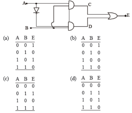
Answer: C
Question. The gate for which output is high if atleast one input is low?
(a) NAND
(b) NOR
(c) AND
(d) OR
Answer: A
Question. Radiowaves of constant amplitude can be generated with
(a) FET
(b) filter
(c) rectifier
(d) oscillator
Answer: D
Question. The current gain β may be defined as
(a) the ratio of change in collector current to the change in emitter current for a constant collector voltage in a common base arrangement.
(b) the ratio of change in collector current to the change in the base current at constant collector voltage in a common emitter circuit
(c) the ratio of change in emitter current to the change in base current for constant emitter voltage in common emitter circuit.
(d) the ratio of change in base current to the change in collector current at constant collector voltage in common emitter circuit.
Answer: B
Question. Current gain of a transistor in common base mode is 0.95. Its value in common emitter mode is
(a) 0.95
(b) 1.5
(c) 19
(d) (19)–1
Answer: C
Question. The intrinsic conductivity of germanium at 27° is 2.13 mho m–1 and mobilities of electrons and holes are 0.38 and 0.18 m2V–1s–1 respectively. The density of charge carriers is
(a) 2.37 × 10¹⁹ m–3
(b) 3.28 × 10¹⁹ m–3
(c) 7.83 × 10¹⁹ m–3
(d) 8.47 × 10¹⁹ m–3
Answer: A
Question. An oscillator is nothing but an amplifier with
(a) positive feedback
(b) large gain
(c) no feedback
(d) negative feedback
Answer: A
Question. The grid voltage of any triode valve is changed from –1 volt to –3 volt and the mutual conductance is 3 × 10⁻⁴ mho. The change in plate circuit current will be
(a) 0.8 mA
(b) 0.6 mA
(c) 0.4 mA
(d) 1 mA
Answer: B
Question. A semi-conducting device is connected in a series circuit with a battery and a resistance. A current is found to pass through the circuit. If the polarity of the battery is reversed, the current drops to almost zero. The device may be
(a) a p-n junction
(b) an intrinsic semi-conductor
(c) a p-type semi-conductor
(d) an n-type semi-conductor
Answer: A
Important Questions for NCERT Class 12 Physics Semiconductor Devices
Question. When arsenic is added as an impurity to silicon, the resulting material is
(a) n-type conductor
(b) n-type semiconductor
(c) p-type semiconductor
(d) none of these.
Answer: B
Question. When n type semiconductor is heated
(a) number of electrons increases while that of holes decreases
(b) number of holes increases while that of electrons decreases
(c) number of electrons and holes remain same
(d) number of electrons and holes increases equally.
Answer: D
Question. The increase in the width of the depletion region in a p-n junction diode is due to
(a) forward bias only
(b) reverse bias only
(c) both forward bias and reverse bias
(d) increase in forward current
Answer: B
Question. The barrier potential of a p-n junction depends on
(1) type of semiconductor material
(2) amount of doping
(3) temperature
Which one of the following is correct?
(a) (1) and (2) only
(b) (2) only
(c) (2) and (3) only
(d) (1), (2) and (3)
Answer: D
Question. In an unbiased p-n junction, holes diffuse from the p-region to n-region because of
(a) he attraction of free electrons of n-region
(b) the higher hole concentration in p-region than that in n-region
(c) the higher concentration of electrons in the n-region than that in the p-region
(d) the potential difference across the p-n junction.
Answer: B
Question. In a p-n junction
(a) high potential at n side and low potential at p side
(b) high potential at p side and low potential at n side
(c) p and n both are at same potential
(d) undetermined.
Answer: A
Question. Depletion layer consists of
(a) mobile ions
(b) protons
(c) electrons
(d) immobile ions
Answer: D
Question. The depletion layer in the p-n junction region is caused by
(a) drift of holes
(b) diffusion of charge carriers
(c) migration of impurity ions
(d) drift of electrons.
Answer: B
Question. In a p-n junction diode, change in temperature due to heating
(a) affects only reverse resistance
(b) affects only forward resistance
(c) does not affect resistance of p-n junction
(d) affects the overall V - I characteristics of p-n junction.
Answer: D
Question. In forward biasing of the p-n junction
(a) the positive terminal of the battery is connected to p-side and the depletion region becomes thick.
(b) the positive terminal of the battery is connected to n-side and the depletion region becomes thin.
(c) the positive terminal of the battery is connected to n-side and the depletion region becomes thick.
(d) the positive terminal of the battery is connected to p-side and the depletion region becomes thin.
Answer: D
Question. Application of a forward bias to a p-n junction
(a) widens the depletion zone
(b) increases the potential difference across the depletion zone
(c) increases the number of donors on the n side
(d) decreases the electric field in the depletion zone.
Answer: D
Question. Reverse bias applied to a junction diode
(a) lowers the potential barrier
(b) raises the potential barrier
(c) increases the majority carrier current
(d) increases the minority carrier current
Answer: B
Question. Barrier potential of a p-n junction diode does not depend on
(a) diode design
(b) temperature
(c) forward bias
(d) doping density
Answer: A
Question. In forward bias, the width of potential barrier in a
p-n junction diode
(a) remains constant
(b) decreases
(c) increases
(d) first (a) then (b)
Answer: B
Question. In a junction diode, the holes are due to
(a) extra electrons
(b) neutrons
(c) protons
(d) missing of electrons
Answer: D
Question. In forward bias, the width of potential barrier in a p-n junction diode
(a) remains constant
(b) decreases
(c) increases
(d) first (a) then (b)
Answer: B
Question. A p-n photodiode is fabricated from a semiconductor with a band gap of 2.5 eV. It can detect a signal of wavelength
(a) 4000 nm
(b) 6000 nm
(c) 4000 Å
(d) 6000 Å
Answer: C
Question. Which of the following gates will have an output of 1? 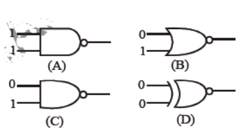
(a) D
(b) A
(c) B
(d) C
Answer: D
Question. Application of a forward bias to a p–n junction
(a) widens the depletion zone
(b) increases the potential difference across the depletion zone
(c) increases the number of donors on the n side
(d) increases the electric field in the depletion zone.
Answer: C
Question. In Boolean algebra, Y = A + B implies that
(a) output Y exists when both inputs A and B exist
(b) output Y exists when either input A exists or input B exists or both inputs A and B exist
(c) output Y exists when either input A exists or input B exists but not when both inputs A and B exist
(d) output Y exists when both inputs A and B exists but not when either input A or B exist
Answer: B
Question. Metallic solids are always opaque because
(a) they reflect all the incident light.
(b) they scatter all the incident light.
(c) the incident light is readily absorbed by the free electrons in a metal.
(d) the energy band traps the incident.
Answer: C
Question. Assuming that the silicon diode having resistance of 20 Ω , the current through the diode is (knee voltage 0.7 V) 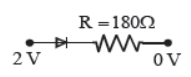
(a) 0 mA
(b) 10 mA
(c) 6.5 mA
(d) 13.5 mA
Answer: C
Question. Which one of the following represents forward bias diode? 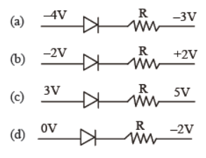
Answer: D
Question. Copper has face centered cubic (fcc) lattice with interatomic spacing equal to 2.54 Å. The value of lattice constant for this lattice is
(a) 2.54 Å
(b) 3.59 Å
(c) 1.27 Å
(d) 5.08 Å
Answer: B
Question. The ratio of work function and temperature of two emitters are 1 : 2, then the ratio of current densities obtained by them will be
(a) 4 : 1
(b) 2 : 1
(c) 1 : 2
(d) 1 : 4
Answer: D
Question. Minority carriers in a p-type semiconductor are
(a) free electrons
(b) holes
(c) neither holes nor free electron
(d) both holes and free electrons.
Answer: A
Question. The intrinsic semi conductor becomes an insulator at
(a) 0ºC
(b) 0 K
(c) 300 K
(d) –100ºC
Answer: B
Question. The transfer ratio b of transistor is 50. The input resistance of a transistor when used in C.E. (Common Emitter) configuration is 1kW. The peak value of the collector A.C current for an A.C input voltage of 0.01V peak is
(a) 100 mA
(b) .01 mA
(c) .25 mA
(d) 500 mA
Answer: D
Question. For transistor action
(1) Base, emitter and collector regions should have similar size and doping concentrations.
(2) The base region must be very thin and lightly doped.
(3) The eimtter-base junction is forward biased and basecollector junction is reverse based.
(4) Both the emitter-base junction as well as the basecollector junction are forward biased.
(a) (3) and (4)
(b) (4) and (1)
(c) (1) and (2)
(d) (2) and (3)
Answer: D
Question. A solid that is not transparent to visible light and whose electrical conductivity increases with temperature is formed by
(a) ionic binding
(b) covalent binding
(c) metallic binding
(d) vander Waal’s binding
Answer: B
Question. In a transistor, the change in base current from 100 μA to 125 μA causes a change in collector current from 5 mA to 7.5 mA, keeping collector-to-emitter voltage constant at 10 V. What is the current gain of the transistor?
(a) 200
(b) 100
(c) 50
(d) 25.
Answer: B
Question. NAND and NOR gates are called universal gates primarily because they
(a) are available universally
(b) can be combined to produce OR, AND and NOT gates
(c) are widely used in Integrated circuit packages
(d) are easiest to manufacture
Answer: B
Question. The following configuration of gate is equivalent to
(a) NAND gate
(b) XOR gate
(c) OR gate
(d) NOR gate
Answer: B
Question. Two junction diodes one of Germanium (Ge) and other of silicon (Si) are connected as shown in figure to a battery of emf 12 V and a load resistance 10 k Ω. The germanium diode conducts at 0.3 V and silicon diode at 0.7 V. When a current flows in the circuit, the potential of terminal Y will be 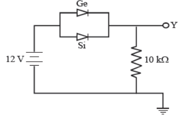
(a) 12 V
(b) 11 V
(c) 11.3 V
(d) 11.7 V
Answer: D
Question. If the ratio of the concentration of electrons to that of holes in a semiconductor is 7/5 and the ratio of currents is 7/4 , then what is the ratio of their drift velocities?
(a) 5/8
(b) 4/5
(c) 5/4
(d) 4/7
Answer: C
Question. The circuit has two oppositively connected ideal diodes in parallel. What is the current flowing in the circuit?
(a) 1.71 A
(b) 2.00 A
(c) 2.31 A
(d) 1.33 A
Answer: B
Question. In figure given below, assuming the diodes to be ideal
(a) D1 is forward biased and D2 is reverse biased and hence current flows from A to B
(b) D2 is forward biased and D1 is reverse biased and hence no current flows from B to A and vice–versa
(c) D1 and D2 are both forward biased and hence current flows from A to B
(d) D1 and D2 are both reverse biased and hence no current flows from A to B and vice – versa 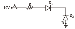
Answer: B
Important Questions for NCERT Class 12 Physics Semiconductor Devices
Question. The following figure shows a logic gate circuit with two inputs A and B and the output Y. The voltage waveforms of A, B and Y are given 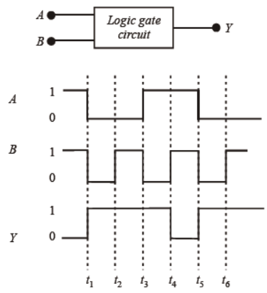
The logic gate is :
(a) NAND gate
(b) NOR gate
(c) OR gate
(d) AND gate
Answer: A
Question. In a junction diode, the holes are due to
(a) protons
(b) extra electrons
(c) neutrons
(d) missing electrons
Answer: D
Question. In a n-type semiconductor, which of the following statement is true?
(a) Electrons are minority carriers and pentavalent atoms are dopants.
(b) Holes are minority carriers and pentavalent atoms are dopants.
(c) Holes are majority carriers and trivalent atoms are dopants.
(d) Electrons are majority carriers and trivalent atoms are dopants.
Answer: B
Question. In figure given below V0 is the potential barrier across a p–n junction, when no battary is connected across the junction 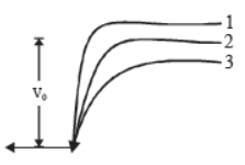
(a) 1 and 3 both correspond to forward bias of junction
(b) 3 corresponds to forward bias of junction and 1 corresponds to reverse bias of junctions
(c) 1 corresponds to forward bias and 3 corresponds to reverse bias of junction
(d) 3 and 1 both correspond to reverse bias of junction
Answer: B
Question. A n-p-n transistor conducts when
(a) both collector and emitter are negative with respect to the base
(b) both collector and emitter are positive with respect to the base
(c) collector is positive and emitter is negative with respect to the base
(d) collector is positive and emitter is at same potential as the base
Answer: C
Question. A TV tower has a height of 100 m. How much population is covered by the TV broadcast if the average population density around the tower is 1000 km–2 ? (radius of the earth = 6.37 × 10⁶ m)
(a) 4 lakh
(b) 4 billion
(c) 40,000
(d) 40 lakh
Answer: D
Question. In a bridge rectifier, the number of diodes required is
(a) 1
(b) 2
(c) 3
(d) 4
Answer: D
Question. Following diagram performs the logic function of 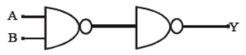
(a) XOR gate
(b) AND gate
(c) NAND gate
(d) OR gate
Answer: B
Question. In the study of transistor as amplifier, if α = IC/IE , where, IC, IB and IE are the collector, base and emitter currents, then
(a) β = (1+α)/α
(b) β = (1-α)/α
(c) β = α/(1-α)
(d) β = α/(1+α)
Answer: C
Question. A 220 V AC supply is connected between points A and B (figure). What will be the potential difference V across the capacitor? 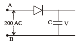
(a) 220 V
(b) 110 V
(c) 0 V
(d) 220 2V
Answer: D
Question. The ratio of forward biased to reverse biased resistance for pn junction diode is
(a) 10–1 : 1
(b) 10–2 : 1
(c) 104 : 1
(d) 10–4 : 1
Answer: D
Question. Hole in semiconductor is
(a) an anti – particle of electron
(b) a vacancy created when an electron leaves a covalent bond
(c) absence of free electrons
(d) an artificially created particle
Answer: B
Question. In germanium the energy gap is about 0.75 eV. The wavelength of light which germanium starts absorbing is
(a) 5000 Å
(b) 1650 Å
(c) 16500 Å
(d) 165000 Å
Answer: C
Question. Transfer characteristics [output voltage (V0) vs input voltage (V1)] for a base biased transistor in CE configuration is as shown in the figure. For using transistor as a switch, it is used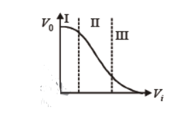
(a) in region (III)
(b) both in region (I) and (III)
(c) in region (II)
(d) in region (I)
Answer: B
Question. In a n-type semiconductor, which of the following statements is true?
(a) Electrons are minority carriers and pentavalent atoms are dopants.
(b) Holes are minority carriers and pentavalent atoms are dopants.
(c) Holes are majority carriers and trivalent atoms are dopants.
(d) Electrons are majority carriers and trivalent atoms are dopants.
Answer: B
Question. The energy gap of silicon is 1.14 eV. The maximum wavelength at which silicon starts energy absorption, will be (h = 6.62 × 10⁻³⁴ Js ; c = 3 × 10⁸ m/s)
(a) 10.888 Å
(b) 108.88 Å
(c) 1088.8 Å
(d) 10888 Å
Answer: A
Question. A zener diode, having breakdown voltage equal to 15V, is used in a voltage regulator circuit shown in figure. The current through the diode is
(a) 10 mA
(b) 15 mA
(c) 20 mA
(d) 5 mA
Answer: D
Question. One way in which the operation of a n-p-n transistor differs from that of a p-n-p
(a) the emitter junction is reversed biased in n-p-n
(b) the emitter junction injects minority carriers into the base region of the p-n-p
(c) the emitter injects holes into the base of the p-n-p and electrons into the base region of n-p-n
(d) the emitter injects holes into the base of n-p-n
Answer: C
Question. The output from a NAND gate is divided into two in parallel and fed to another NAND gate. The resulting gate is a
(a) NOT gate
(b) AND gate
(c) NOR gate
(d) OR gate
Answer: B
Question. The given graph represents V - I characteristic for a semiconductor device. Which of the following statement is correct ?
(a) It is V - I characteristic for solar cell where, point A represents open circuit voltage and point B short circuit current.
(b) It is a for a solar cell and point A and B represent open circuit voltage and current, respectively.
(c) It is for a photodiode and points A and B represent open circuit voltage and current, respectively.
(d) It is for a LED and points A and B represent open circuit voltage and short circuit current, respectively.
Answer: A
Question. The barrier potential of a p-n junction depends on:
(A) type of semi conductor material
(B) amount of doping
(C) temperature
Which one of the following is correct ?
(a) (A) and (B) only
(b) (B) only
(c) (B) and (C) only
(d) (A), (B) and (C)
Answer: D
Question. The cause of the potential barrier in a p-n junction diode is
(a) depletion of negative charges near the junction
(b) concentration of positive charges near the junction
(c) depletion of positive charges near the junction
(d) concentration of positive and negative charges near the junction.
Answer: D
Question. A semiconducting device is connected in a series circuit with a battery and a resistance. A current is found to pass through the circuit. If the polarity of the battery is reversed, the current drops to almost zero. The device may be
(a) a p-type semiconductor
(b) an intrinsic semiconductor
(c) a p-n junction
(d) an n-type semiconductor.
Answer: C
Question. If a full wave rectifier circuit is operating from 50 Hz mains, the fundamental frequency in the ripple will be
(a) 25 Hz
(b) 50 Hz
(c) 70.7 Hz
(d) 100 Hz
Answer: D
Question. A p-n junction diode can be used as
(a) condenser
(b) regulator
(c) amplifier
(d) rectifier
Answer: D
Question. An LED is constructed from a p-n junction diode using GaAsP. The energy gap is 1.9 eV. The wavelength of the light emitted will be equal to
(a) 10.4 × 10⁻²⁶ m
(b) 654 nm
(c) 654 Å
(d) 654 × 10–11 m
Answer: B
Question. A p-n photodiode is fabricated from a semiconductor with a band gap of 2.5 eV. It can detect a signal of wavelength
(a) 4000 nm
(b) 6000 nm
(c) 4000 Å
(d) 6000 Å
Answer: C
Question. A p-n photodiode is made of a material with a band gap of 2.0 eV. The minimum frequency of the radiation that can be absorbed by the material is nearly
(a) 1 × 10¹⁴ Hz
(b) 20 × 1014 Hz
(c) 10 × 1014 Hz
(d) 5 × 10¹⁴ Hz
Answer: D
Question. Zener diode is used for
(a) amplification
(b) rectification
(c) stabilisation
(d) producing oscillations in an oscillator.
Answer: C
Question. In a p-n junction photo cell, the value of the photoelectromotive force produced by monochromatic light is proportional to
(a) the barrier voltage at the p-n junction
(b) the intensity of the light falling on the cell
(c) the frequency of the light falling on the cell
(d) the voltage applied at the p-n junction.
Answer: B
Question. The device that can act as a complete electronic circuit is
(a) junction diode
(b) integrated circuit
(c) junction transistor
(d) zener diode.
Answer: B
Question. For transistor action, which of the following statements is correct?
(a) Base, emitter and collector regions should have same doping concentrations.
(b) Base, emitter and collector regions should have same size.
(c) Both emitter junction as well as the collector junction are forward biased.
(d) The base region must be very thin and lightly doped.
Answer: D
Question. In a common emitter transistor amplifier the audio signal voltage across the collector is 3 V. The resistance of collector is 3 kW. If current gain is 100 and the base resistance is 2 kW, the voltage and power gain of the amplifier is
(a) 15 and 200
(b) 150 and 15000
(c) 20 and 2000
(d) 200 and 1000
Answer: B
Question. For CE transistor amplifier, the audio signal voltage across the collector resistance of 2 kW is 4 V. If the current amplification factor of the transistor is 100 and the base resistance is 1 kW, then the input signal voltage is
(a) 10 mV
(b) 20 mV
(c) 30 mV
(d) 15 mV
Answer: B
Question. A npn transistor is connected in common emitter configuration in a given amplifier. A load resistance of 800 W is connected in the collector circuit and the voltage drop across it is 0.8 V. If the current amplification factor is 0.96 and the input resistance of the circuit is 192 W, the voltage gain and the power gain of the amplifier will respectively be
(a) 4, 4
(b) 4, 3.69
(c) 4, 3.84
(d) 3.69, 3.84
Answer: C
Question. In a CE transistor amplifier, the audio signal voltage across the collector resistance of 2 kW is 2 V. If the base resistance is 1 kW and the current amplification of the transistor is 100, the input signal voltage is
(a) 0.1 V
(b) 1.0 V
(c) 1 mV
(d) 10 mV
Answer: D
Question. If a full wave rectifier circuit is operating from 50 Hz mains, the fundamental frequency in the ripple will be
(a) 25 Hz
(b) 50 Hz
(c) 70.7 Hz
(d) 100 Hz
Answer: D
Question. A p-n junction diode can be used as
(a) condenser
(b) regulator
(c) amplifier
(d) rectifier
Answer: D
Question. An LED is constructed from a p-n junction diode using GaAsP. The energy gap is 1.9 eV. The wavelength of the light emitted will be equal to
(a) 10.4 × 10⁻²⁶ m
(b) 654 nm
(c) 654 Å
(d) 654 × 10–11 m
Answer: B
Question. The cause of the potential barrier in a p-n junction diode is
(a) depletion of negative charges near the junction
(b) concentration of positive charges near the junction
(c) depletion of positive charges near the junction
(d) concentration of positive and negative charges near the junction.
Answer: D
Question. A semiconducting device is connected in a series circuit with a battery and a resistance. A current is found to pass through the circuit. If the polarity of the battery is reversed, the current drops to almost zero. The device may be
(a) a p-type semiconductor
(b) an intrinsic semiconductor
(c) a p-n junction
(d) an n-type semiconductor
Answer: C
Question. Barrier potential of a p-n junction diode does not depend on
(a) diode design
(b) temperature
(c) forward bias
(d) doping density
Answer: A
Important Questions for NCERT Class 12 Physics Semiconductor Devices
Question. The input resistance of a silicon transistor is 100 W.
Base current is changed by 40 mA which results in a change in collector current by 2 mA. This transistor is used as a common emitter amplifier with a load resistance of 4 kW. The voltage gain of the amplifier is
(a) 2000
(b) 3000
(c) 4000
(d) 1000
Answer: A
Question. A transistor is operated in common emitter configuration at VC = 2 V such that a change in the base current from 100 mA to 300 mA produces a change in the collector current from 10 mA to 20 mA. The current gain is
(a) 50
(b) 75
(c) 100
(d) 25
Answer: A
Question. A common emitter amplifier has a voltage gain of 50, an input impedance of 100 W and an output impedance of 200 W. The power gain of the amplifier is
(a) 500
(b) 1000
(c) 1250
(d) 50
Answer: C
Question. A transistor is operated in common-emitter configuration at VC = 2 V such that a change in the base current from 100 mA to 200 mA produces a change in the collector current from 5 mA to10 mA.
The current gain is
(a) 100
(b) 150
(c) 50
(d) 75
Answer: C
Question. The voltage gain of an amplifier with 9% negative feedback is 10. The voltage gain without feedback will be
(a) 1.25
(b) 100
(c) 90
(d) 10
Answer: B
Question. A transistor is operated in common emitter configuration at constant collector voltage VC = 1.5 V such that a change in the base current from 00 mA to 150 mA produces a change in the collector current from 5 mA to 10 mA. The current gain b is
(a) 50
(b) 67
(c) 75
(d) 100
Answer: D
Question. The transfer ratio b of a transistor is 50. The input resistance of the transistor when used in the commonemitter configuration is 1 kW. The peak value of the collector A.C. current for an A.C. input voltage of 0.01 V peak is
(a) 0.25 mA
(b) 0.01 mA
(c) 100 mA
(d) 500 mA
Answer: D
Question. When npn transistor is used as an amplifier, then
(a) electrons move from collector to base
(b) holes move from base to emitter
(c) electrons move from base to collector
(d) electrons move from emitter to base.
Answer: C
Question. The part of the transistor which is heavily doped to produce large number of majority carriers is
(a) emitter
(b) base
(c) collector
(d) any of the above depending upon the nature of transistor
Answer: A
Question. To use a transistor as an amplifier
(a) the emitter base junction is forward biased and the base collector junction is reversed biased
(b) no bias voltage is required
(c) both junction are forward biased
(d) both junction are reverse biased.
Answer: A
Question. Radiowaves of constant amplitude can be generated with
(a) FET
(b) filter
(c) rectifier
(d) oscillator
Answer: D
Question. Which one of the following bonds produces a solid that reflects light in the visible region and whose electrical conductivity decreases with temperature and has high melting point?
(a) metallic bonding
(b) van der Waal’s bonding
(c) ionic bonding
(d) covalent bonding
Answer: A
Question. Sodium has body centred packing. Distance between two nearest atoms is 3.7 Å. The lattice parameter is
(a) 4.3 Å
(b) 3.0 Å
(c) 8.6 Å
(d) 6.8 Å
Answer: A
Question. If the lattice parameter for a crystalline structure is 3.6 Å, then the atomic radius in fcc crystal is
(a) 2.92 Å
(b) 1.27 Å
(c) 1.81 Å
(d) 2.10 Å
Answer: B
Question. In a p-n junction
(a) high potential at n side and low potential at p side
(b) high potential at p side and low potential at n side
(c) p and n both are at same potential
(d) undetermined.
Answer: A
Question. The device that can act as a complete electronic circuit is
(a) junction diode
(b) integrated circuit
(c) junction transistor
(d) zener diode.
Answer: B
Question. The increase in the width of the depletion region in a p-n junction diode is due to
(a) forward bias only
(b) reverse bias only
(c) both forward bias and reverse bias
(d) increase in forward current
Answer: B
Question. For transistor action, which of the following statements is correct?
(a) Base, emitter and collector regions should have same doping concentrations.
(b) Base, emitter and collector regions should have same size.
(c) Both emitter junction as well as the collector junction are forward biased.
(d) The base region must be very thin and lightly doped.
Answer: D
Question. Zener diode is used for
(a) amplification
(b) rectification
(c) stabilisation
(d) producing oscillations in an oscillator.
Answer: C
Question. In a p-n junction photo cell, the value of the photoelectromotive force produced by monochromatic light is proportional to
(a) the barrier voltage at the p-n junction
(b) the intensity of the light falling on the cell
(c) the frequency of the light falling on the cell
(d) the voltage applied at the p-n junction.
Answer: B
Question. In a p-n junction diode, change in temperature due to heating
(a) affects only reverse resistance
(b) affects only forward resistance
(c) does not affect resistance of p-n junction
(d) affects the overall V - I characteristics of p-n junction.
Answer: D
Question. In forward biasing of the p-n junction
(a) the positive terminal of the battery is connected to p-side and the depletion region becomes thick.
(b) the positive terminal of the battery is connected to n-side and the depletion region becomes thin.
(c) the positive terminal of the battery is connected to n-side and the depletion region becomes thick.
(d) the positive terminal of the battery is connected to p-side and the depletion region becomes thin.
Answer: D
Question. Application of a forward bias to a p-n junction
(a) widens the depletion zone
(b) increases the potential difference across the depletion zone
(c) increases the number of donors on the n side
(d) decreases the electric field in the depletion zone.
Answer: D
Question. Reverse bias applied to a junction diode
(a) lowers the potential barrier
(b) raises the potential barrier
(c) increases the majority carrier current
(d) increases the minority carrier current
Answer: B
Question. In a junction diode, the holes are due to
(a) extra electrons
(b) neutrons
(c) protons
(d) missing of electrons
Answer: D
Question. Which logic gate is represented by the following combination of logic gate ? 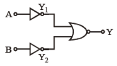
(a) NAND
(b) AND
(c) NOR
(d) OR
Answer: B
Question. If in a p-n junction, a square input signal of 10 V is applied as shown, then the output across RL will be 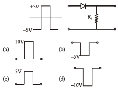
Answer: C
Question. In the given figure, a diode D is connected to an external resistance R = 100 Ω and an e.m.f. of 3.5 V. If the barrier potential developed across the diode is 0.5 V, the current in the circuit will be:
(a) 40 mA
(b) 20 mA
(c) 35 mA
(d) 30 mA
Answer: D
Question. The input signal given to a CE amplifier having a voltage gain of 150 is Vi = 2 cos (15t + π/3) . The corresponding output signal will be : 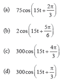
Answer: C
Question. Consider the junction diode as ideal. The value of current flowing through AB is :
(a) 0 A
(b) 10–2 A
(c) 10–1 A
(d) 10–3 A
Answer: B
Question. Two ideal diodes are connected to a battery as shown in the circuit. The current supplied by the battery is 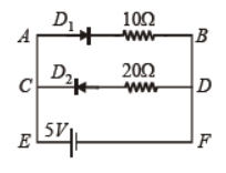
(a) 0.75 A
(b) zero
(c) 0.25 A
(d) 0.5 A
Answer: D
Question. The value of β
(a) is always less than 1
(b) lies between 20 and 200
(c) is always greater than 200
(d) is always infinity
Answer: B
Question. In an unbiased p-n junction, holes diffuse from the p-region to n-region because of
(a) the potential difference across the p-n junction
(b) the attraction of free electrons of n-region
(c) the higher hole concentration in p-region than that in n-region
(d) the higher concentration of electrons in the n-region than that in the p-region
Answer: C
Question. To get output 1 for the following circuit, the correct choice for the input is
(a) A = 0, B = 1, C = 0
(b) A = 1, B = 0, C = 0
(c) A = 1, B = 1, C = 0
(d) A = 1, B = 0, C = 1
Answer: D
Question. In a common emitter transistor amplifier the audio signal voltage across the collector is 3V. The resistance of collector is 3 kΩ. If current gain is 100 and the base resistance is 2 kΩ, the voltage and power gain of the amplifier is
(a) 15 and 200
(b) 150 and 15000
(c) 20 and 2000
(d) 200 and 1000
Answer: B
Question. The given electrical network is equivalent to :
(a) OR gate
(b) NOR gate
(c) NOT gate
(d) AND gate
Answer: B
Question. The input resistance of a silicon transistor is 100 W. Base current is changed by 40 mA which results in a change in collector current by 2 mA. This transistor is used as a common emitter amplifier with a load resistance of 4 KW. The voltage gain of the amplifier is
(a) 2000
(b) 3000
(c) 4000
(d) 1000
Answer: A
Question. In a common emitter (CE) amplifier having a voltage gain G, the transistor used has transconductance 0.03 mho and current gain 25. If the above transistor is replaced with another one with transconductance 0.02 mho and current gain 20, the voltage gain will be
(a) 1.5 G
(b) 1/3 G
(c) 5/4 G
(d) 2/3 G
Answer: D
Directions for : Each question contains STATEMENT-1 and STATEMENT-2. Choose the correct answer from the following-
(a) Statement -1 is true, Statement-2 is true; Statement -2 is a correct explanation for Statement-1
(b) Statement -1 is true, Statement-2 is true; Statement -2 is not a correct explanation for Statement-1
(c) Statement -1 is true, Statement-2 is false
(d) Statement -1 is false, Statement-2 is true
Question. Statement-1 : NOT gate is also called invertor circuit.
Statement-2 : NOT gate inverts the input order.
Answer: A
Question. Statement 1 : If the temperature of a semiconductor is increased then it’s resistance decreases.
Statement 2 : The energy gap between conduction band and valence band is very small.
Answer: A
Question. Statement 1 : A pure semiconductor has negative temperature coefficient of resistance.
Statement 2 : In a semiconductor on raising the temperature, more charge carriers are released, conductance increases and resistance decreases.
Answer: A
Question. Statement-1 : When two semi conductor of p and n type are brought in contact, they form p-n junction which act like a rectifier.
Statement-2 : A rectifier is used to convent alternating current into direct current.
Answer: B
Question. Statement 1 : Diode lasers are used as optical sources in optical communication.
Statement 2 : Diode lasers consume less energy.
Answer: C
Question. Statement 1 : A transistor amplifier in common emitter configuration has a low input impedence.
Statement 2 : The base to emitter region is forward-biased.
Answer: A
Question. Statement-1 : NAND or NOR gates are called digital building blocks.
Statement-2 : The repeated use of NAND (or NOR) gates can produce all the basis or complicated gates.
Answer: A
SOLID AND SEMICONDUCTOR DEVICES (EASY AND SCORING TOPIC)
- Distinction of metals, semiconductor and insulator on the basis of Energy band of Solids.
- Types of Semiconductor.
- PN Junction formation
- Diode characteristics.
- Diode as a rectifier
- Symbol and sections of transistor.
- Transistor as an Amplifier.
- Basic logic gates.
Energy Bands of Solids
1. Energy Band In a crystal due to interatomic interaction valence electrons of one atom are shared by more than one atom in the crystal. Now splitting of energy levels takes place. The collection of these closely spaced energy levels is called an energy band.
2. Valence Band This energy band contains valence electrons. This band may be Partially or completely filled with electrons but never be empty. The electrons in this band are not capable of gaining energy from external electric field to take part in conduction of current.
3. Conduction Band This band contains conduction electrons. This band is either empty or Partially filled with electrons. Electrons present in this band take part in the conduction of current.
4. Forbidden Band This band is completely empty. The minimum energy required to shift an electron from valence band to conduction band is called band gap (\( E_g \)).
Types of Semiconductor
(i) Intrinsic Semiconductor: A semiconductor in its pure state is called intrinsic semiconductor.
(ii) Extrinsic Semiconductor: A semiconductor doped with suitable impurity to increase its conductivity, is called extrinsic semiconductor.
On the basis of doped impurity extrinsic semiconductors are of two types:
(i) n-type Semiconductor: Extrinsic semiconductor doped with pentavalent impurity like As, Sb, Bi, etc in which negatively charged electrons works as charge carrier, is called n-type semiconductor. Every pentavalent impurity atom donate one electron in the crystal, therefore it is called a donor atom.
(ii) p-type Semiconductor: Extrinsic semiconductor doped with trivalent impurity like Al, B, etc, in which positively charged holes works as charge carriers, is called p-type semiconductor. Every trivalent impurity atom have a tendency to accept one electron, therefore it is called an acceptor atom.
In a doped semiconductor \( n_e n_h = n_i^2 \) where \( n_e \) and \( n_h \) are the number density of electrons and holes and \( n_i \) is number density of intrinsic carriers, i.e., electrons or holes.
In n-type semiconductor, \( n_e \gg n_h \)
In p-type semiconductor, \( n_h \gg n_e \)
PN Junction
An arrangement consisting a p-type semiconductor brought into a close contact with n-type Semiconductor is called a p-n junction.
Terms Related to p-n junction
(i) Depletion Layer: At p-n junction a region is created, where there is no charge carriers. This region is called depletion layer. The width of this region is of the order of \( 10^{-6}\text{ m} \).
(ii) Potential Barrier: The potential difference across the depletion layer is called potential barrier. Barrier potential for Ge is \( 0.3\text{ V} \) and for Si is \( 0.7\text{ V} \).
(iii) Forward biasing: In this biasing, the p-side is connected to positive terminal and n-side to negative terminal of a battery.
In this biasing, forward current flows due to majority charge carriers.
The width of depletion layer decreases.
(iv) Reverse biasing: In this biasing, the p-side is connected to negative terminal and n-side to positive terminal of a battery.
In this biasing, reverse current flow due to minority charge carriers.
The width of depletion layer increases.
Resistance of a Diode
(i) Static or DC Resistance: \( R_{d.c} = \frac{V}{I} \)
(ii) Dynamic or AC Resistance: \( R_{a.c} = \frac{\Delta V}{\Delta I} \)
Rectifier
A device which converts alternating current or voltage into direct current or voltage is known as rectifier.
The process of converting AC into DC is rectification.
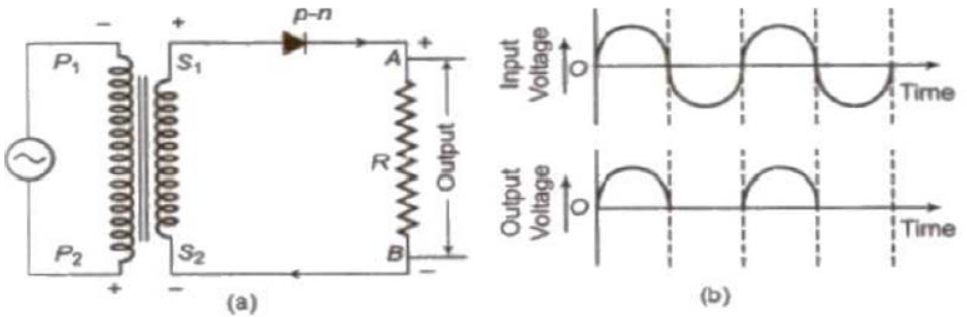
Half-Wave Rectifier: A half-wave rectifier converts the half cycle of applied AC signal into DC signal.
During the positive half the \( S_2 \) end of secondary is negative and \( S_1 \) positive. Now the diode is in forward bias and the current flows through resistance R shown in upper figure.
During the negative half the \( S_1 \) end of secondary is negative and \( S_2 \) positive. Now the junction Diode is in reverse bias and so there is negligible (No current) through resistance R. Hence we get the output as D.C. but half of the input A.C. is rectified.
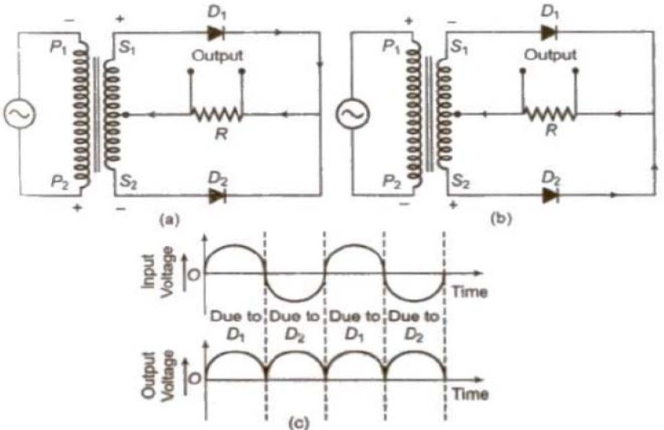
Full-Wave Rectifier: A full-wave rectifier converts the whole cycle of applied AC signal into DC signal. Centre tap, transformer is used here.
For full wave rectification, we have to use two P-N junctions. During the positive half of the input A.C. the upper P-N junction diode is forward biased and the lower P-N junction diode is reverse biased. The forward current flows on account of majority carriers of upper P-N junction diode.
During the negative half cycle of input of A.C. the upper P-N junction diode is reverse biased, and the lower P-N junction diode is forward biased. The forward current flows on account of majority carriers of lower p-n junction diode. We observe that during both the halves, current through R flows in the same direction. The input and output waveforms are shown in fig. The output signal voltage is unidirectional having ripple contents, i.e D.C components and A.C components both.
Transistor
A transistor is an arrangement obtained by growing a thin layer of one type of semiconductor between two thick layers of other similar type semiconductor.
Transistor as an Amplifier
An amplifier is a device which is used for increasing the amplitude of variation of alternating voltage, current or power.
The amplifier thus produces an enlarged version of the input signal.
The general concept of amplification is represented in figure. There are two input terminals for the signal to be amplified and two output terminals for connecting the load; and a means of supplying power to the amplifier.
Common Emitter Amplifier
It is N-P-N transistor in common emitter configuration.
When no input A.C. signal is applied to the Base-Emitter circuit then the output voltage across the collector circuit can be written as
\( V_c = V_{CE} - I_c R_L \)
\( V_c \) is the potential difference across C and E.
During +ve half of the input A.C. signal, the forward bias increases. It increases input current and so output current also increases. \( I_c R_L \) also increases. Therefore \( V_C \) increases and it makes collector more negative i.e input signal is amplified but in the opposite phase.
During -ve half of the input A.C. signal, the forward bias decreases. It decreases input current and so output current also decreases. \( I_c R_L \) also decreases. Therefore \( V_C \) decreases and it makes collector more positive i.e input signal is amplified but in the opposite phase.
Light Emitting Diodes (LED)
It is forward biased p-n junction diode which emits light when recombination of electrons and holes takes place at the junction. If the semiconducting material of p-n junction is transparent to light, the light is emitting and the junction becomes a light source, i.e., Light Emitting Diode (LED). The colour of the light depends upon the types of material used in making the semiconductor diode.
- (i) Gallium – Arsenide (Ga-As) – Infrared radiation
- (ii) Gallium – phosphide (GaP) – Red or green light
- (iii) Gallium – Arsenide – phosphide (GaAsP) – Red or yellow light
Logic Gate
A digital circuit which allows a signal to pass through it, only when few logical relations are satisfied, is called a logic gate.
Truth Table
A table which shows all possible input and output combinations is called a truth table.
Basic Logic Gates
(i) OR Gate: It is a two input and one output logic gate.
Boolean expression \( Y = A + B \) (Y equals A OR B)
(ii) AND Gate: It is a two input and one output logic gate.
Boolean expression \( Y = A \cdot B \) (Y equals A AND B)
(iii) NOT Gate: It is a one input and one output logic gate.
Boolean expression \( Y = \bar{A} \) (Y equals NOT A)
(iv) NAND Gate: When output of AND gate is applied as input to a NOT gate, then it is called a NAND gate. Boolean expression \( Y = \overline{A \cdot B} \) (Y equals negated of A AND B)
(v) NOR Gate: When output of OR gate is applied as input to a NOT gate, then it is called a NOR gate.
Boolean expression \( Y = \overline{A + B} \) (Y equals negated of A OR B)
IMPORTANT QUESTIONS
Question. Important Energy level Diagrams:
Answer:
METAL: The electrons in valence band overflow into conduction band and are free to move about in the crystal for conduction.
SEMICONDUCTOR (INTRINSIC): At absolute zero temperature, no electron has energy to jump from valence band to conduction band and hence the crystal is an insulator. At room temperature, some valence electrons gain energy more than the energy gap and move to conduction band to conduct even under the influence of a weak electric field. \( \frac{n_e}{n_h} = 1 \)
INSULATOR: Electrons cannot practically jump to conduction band from valence band due to a large energy gap. Therefore, conduction is not possible in insulators.
P-TYPE SEMICONDUCTOR: The energy difference between the acceptor energy level and the top of the valence band is much smaller than the band gap. Electrons from the valence band can, therefore, easily move into the acceptor level by being thermally agitated. \( \frac{n_h}{n_e} > 1 \)
N-TYPE SEMICONDUCTOR: The energy state corresponding to the fifth electron is in the forbidden gap and slightly below the lower level of the conduction band. This energy level is called ‘donor level’. \( \frac{n_e}{n_h} > 1 \)
Question. Why is silicon preferred to germanium in manufacturing semiconductors?
Answer: Silicon is preferred to germanium in manufacturing semiconductors because of the following reasons:
• Silicon has high temperature coefficient than germanium.
• Silicon can operate at high temperature than germanium.
• Silicon is comparatively cheaper.
Question. Distinction between Intrinsic and Extrinsic Semiconductor
Answer:
Intrinsic Semiconductor:
• Pure Group IV elements.
• Conductivity is only slight.
• Conductivity increases with rise in temperature.
• The number of holes is always equal to the number of free electrons.
Extrinsic Semiconductor:
• Group III or Group V elements are introduced in Group IV elements.
• Conductivity is greatly increased.
• Conductivity depends on the amount of impurity added.
• In N-type, the no. of electrons is greater than that of the holes and in P-type, the no. of holes is greater than that of the electrons.
Question. You are given three semiconductors A, B, C with respective band gaps of \( 3\text{ eV} \), \( 2\text{ eV} \) and \( 1\text{ eV} \) for use in a photo detector to detect \( \lambda = 1400\text{ nm} \). Select the suitable semiconductor. Give reasons.
Answer: Energy corresponding to \( \lambda = 1400\text{ nm} = 1400 \times 10^{-9}\text{ m} \) is
\( E = \frac{hc}{\lambda} = \frac{1.42 \times 10^{-19}}{1.6 \times 10^{-19}}\text{ eV} \)
For detection \( E \) must be equal to greater than \( E_g \). Hence only suitable semiconductor is C.
Question. The ratio of number of free electrons to holes \( \frac{n_e}{n_h} \) for two different materials A and B are \( 1 \) and \( <1 \) respectively. Name the type of semiconductor to which A and B belongs.
Answer: If \( \frac{n_e}{n_h} = 1 \), hence A is intrinsic semiconductor.
If \( \frac{n_e}{n_h} < 1 \) (\( n_e < n_h \)), hence B is P-type.
Question. In half wave rectification, what is the output frequency if the input frequency is \( 50\text{ Hz} \). What is the output frequency of a full wave rectification for the same input frequency.
Answer: For half wave rectification \( 50\text{ Hz} \). For Full wave rectification \( 100\text{ Hz} \).
Question. In a given diagram, is the diode reverse (or) forward biased?
Answer: Reverse biased.
Solid and Semiconductor Devices
This chapter explores the fundamental physics and applications of solid-state electronic devices, focusing on semiconductors, p-n junctions, transistors, and basic logic gates.
Topic Outline
- Distinction of metals, semiconductor and insulator on the basis of Energy band of Solids
- Types of Semiconductor
- PN Junction formation
- Diode characteristics
- Diode as a rectifier
- Symbol and sections of transistor
- Transistor as an Amplifier
- Basic logic gates
Energy Bands of Solids
In a crystalline structure, the mutual interaction between atoms causes the outer valence electrons of any single atom to be shared with neighboring atoms. This interaction leads to the dividing or splitting of energy levels. An energy band refers to the group or collection of these tightly packed energy levels.
1. Valence Band
This specific band is occupied by valence electrons. It can be fully or partially occupied, but it is never completely vacant. Because the electrons residing in this band cannot easily acquire energy from an applied external electric field, they do not participate in electric current conduction.
2. Conduction Band
Composed of conduction electrons, this band is either entirely empty or partially populated with electrons. The electrons residing within this band are free to participate in electrical conduction.
3. Forbidden Band
This band remains completely unoccupied. The smallest amount of energy needed to move an electron from the valence band to the conduction band is defined as the band gap \( E_g \).
Types of Semiconductors
Semiconductors are broadly classified based on their purity and the presence of dopants:
- Intrinsic Semiconductor: A semiconductor in its completely pure form, free from any added impurities.
- Extrinsic Semiconductor: A semiconductor created by introducing a small, controlled amount of appropriate impurities (doping) into a semiconductor to boost its electrical conductivity.
Based on the type of dopant added, extrinsic semiconductors are categorized into two kinds:
- n-type Semiconductor: An extrinsic semiconductor doped with a pentavalent impurity (such as arsenic, antimony, or bismuth), where negative electrons serve as the dominant charge carriers. Since each pentavalent dopant atom provides a free electron to the lattice, it is referred to as a donor atom.
- p-type Semiconductor: A p-type semiconductor is formed by doping an intrinsic semiconductor with a trivalent impurity (like aluminum or boron), where positive holes act as the main charge carriers. Each trivalent dopant atom has an affinity to take in an electron from the crystal, which is why it is known as an acceptor atom.
In any doped semiconductor, the relationship \( n_e n_h = n_i^2 \) holds true, where \( n_e \) represents the electron concentration, \( n_h \) represents the hole concentration, and \( n_i \) is the concentration of intrinsic charge carriers (either electrons or holes).
- In n-type semiconductors: \( n_e \gg n_h \)
- In p-type semiconductors: \( n_h \gg n_e \)
PN Junction
A p-n junction is formed when a p-type semiconductor and an n-type semiconductor are brought into intimate, atomic-level contact.
Terms Related to p-n Junction
- Depletion Layer: A region devoid of mobile charge carriers forms at the interface of a p-n junction. This zone is called the depletion layer, and its thickness is typically around \( 10^{-6} \) meters.
- Potential Barrier: The built-in electrical potential difference that develops across the depletion zone is termed the potential barrier. For germanium, this barrier potential is roughly \( 0.3\text{ V} \), whereas for silicon, it is around \( 0.7\text{ V} \).
- Forward Biasing: This configuration involves connecting the p-type region to the positive pole and the n-type region to the negative pole of an external voltage source. In this state, an electric current flows easily because of the movement of majority charge carriers, causing the depletion layer's width to shrink.
- Reverse Biasing: In this setup, the p-type side is attached to the negative terminal of the power supply, while the n-type side connects to the positive terminal. Under reverse bias, only a tiny leakage current flows via the minority charge carriers, and the depletion layer becomes wider.
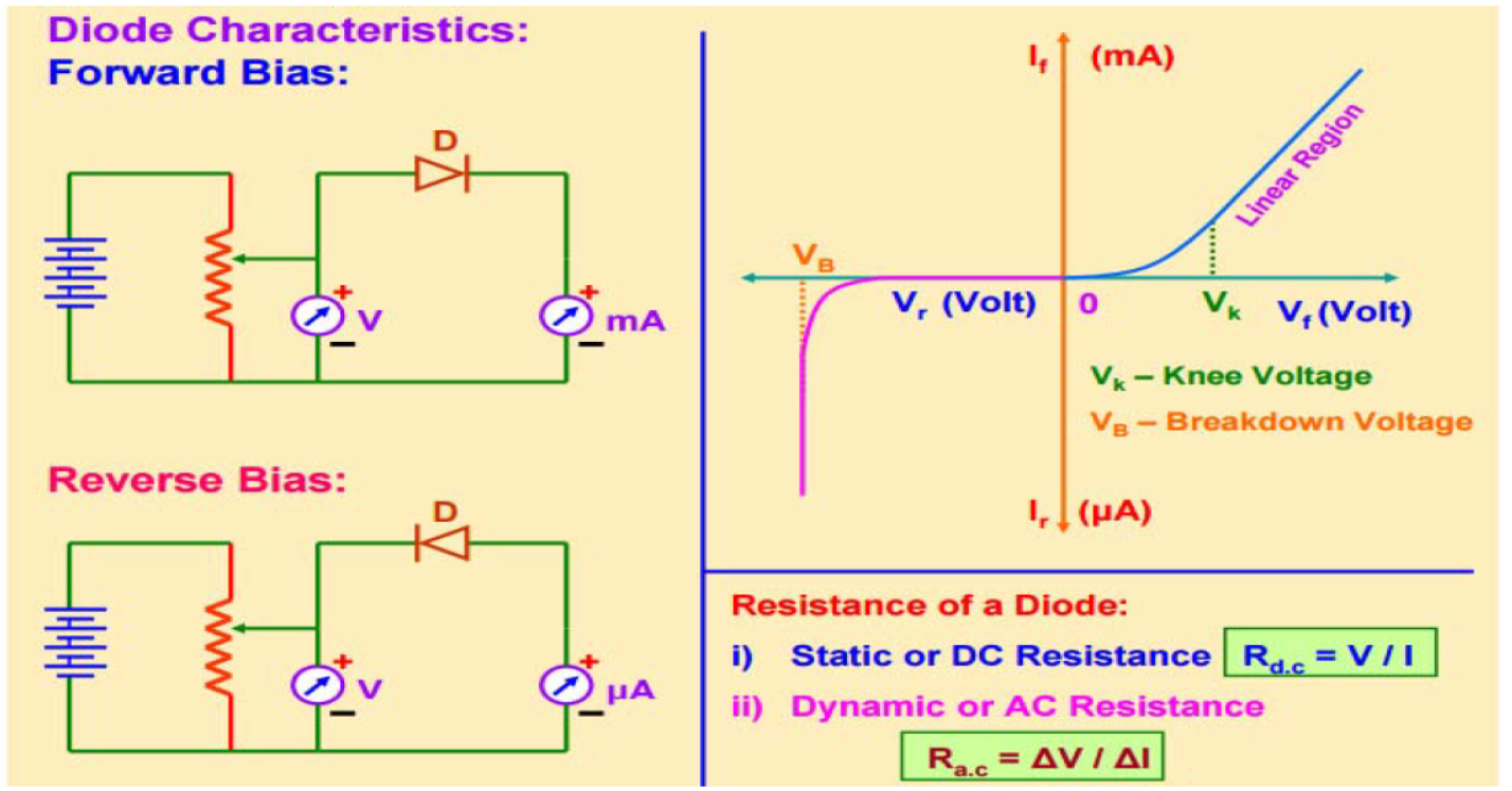
Diode Resistance
- Static (DC) Resistance: This refers to the diode's resistance under steady direct current conditions, calculated using the ratio of operating voltage to the corresponding current: \[ R_{\text{d.c.}} = \frac{V}{I} \]
- Dynamic (AC) Resistance: This measures the opposition to changing currents, determined by the ratio of a small change in voltage to the resulting change in current: \[ R_{\text{a.c.}} = \frac{\Delta V}{\Delta I} \]
Rectifiers
An electrical component designed to transform alternating current (AC) or voltage into direct current (DC) or voltage is called a rectifier. This conversion process itself is termed rectification.
- Half-Wave Rectifier: A half-wave rectifier is designed to convert only one-half of the incoming AC cycle into a unidirectional DC signal.
- Positive Half-Cycle: The terminal \( S_1 \) of the transformer secondary winding becomes positive relative to \( S_2 \). This forward-biases the diode, allowing current to flow through the load resistor \( R \).
- Negative Half-Cycle: The polarities reverse, making \( S_1 \) negative relative to \( S_2 \). The diode enters a reverse-biased state, leading to a negligible current flow across the load resistor \( R \). Consequently, only half of the complete AC wave is converted into DC.
- Full-Wave Rectifier: A full-wave rectifier converts both halves of the alternating current input cycle into a continuous, unidirectional direct current. This configuration typically employs a center-tapped transformer alongside two distinct p-n junction diodes.
- Positive Half-Cycle: The top diode becomes forward-biased while the bottom diode becomes reverse-biased. Current passes through the load resistor \( R \) solely due to the top diode's majority carriers.
- Negative Half-Cycle: The top diode becomes reverse-biased, whereas the bottom diode is forward-biased. Current continues to flow through the load resistor \( R \) in the same direction as before, now driven by the bottom diode.
Transistors and Amplifiers
A transistor is a solid-state component created by sandwiching a very thin layer of one semiconductor type (either p-type or n-type) between two thicker layers of the opposite semiconductor type.
- p-n-p Transistor: Created by placing a thin n-type layer between two thicker p-type layers.
- n-p-n Transistor: Created by placing a thin p-type layer between two thicker n-type layers.
An amplifier is an electronic circuit designed to boost the magnitude of an alternating signal's voltage, current, or overall power, delivering an enlarged replica of the input waveform.
Common Emitter (CE) Amplifier
This setup uses an n-p-n transistor arranged in a common-emitter configuration. When there is no AC signal at the base-emitter input, the steady-state output voltage across the collector-emitter circuit is given by:
\[ V_c = V_{CE} - I_c R_L \]
- Positive Half-Cycle of Input: The forward bias of the emitter-base junction increases, raising the base current. This leads to a corresponding rise in the collector current \( I_c \). Consequently, the voltage drop across the load, \( I_c R_L \), increases. According to the equation, this causes the collector potential \( V_c \) to drop (become more negative). Thus, the output signal is amplified but inverted by \( 180^\circ \) (opposite phase).
- Negative Half-Cycle of Input: The forward bias across the emitter-base junction drops, which reduces the base current and lowers the collector current \( I_c \). As a result, the voltage drop \( I_c R_L \) decreases, making the collector potential \( V_c \) rise (become more positive). The output remains amplified but out of phase with the input.
Light Emitting Diodes (LED)
An LED is a specialized p-n junction diode operated under forward bias that releases light when electrons and holes recombine at the junction barrier. If the semiconductor material is transparent to optical wavelengths, this emitted radiation can escape, turning the junction into an active light source. The specific wavelength or color of the emitted light is determined by the band gap energy of the materials used to construct the diode.
Common semiconductor compounds used for LEDs include:
- Gallium Arsenide (GaAs): Produces infrared emissions.
- Gallium Phosphide (GaP): Produces red or green light.
- Gallium Arsenide Phosphide (GaAsP): Produces red or yellow light.
Logic Gates
A logic gate is an electronic circuit designed to process digital signals, permitting them to propagate only when specific, predefined logical criteria are met.
A truth table is a structured matrix that displays every possible combination of inputs alongside their corresponding output values.
1. OR Gate
Boolean expression: \( Y = A + B \)
| Input A | Input B | Output Y |
|---|---|---|
| 0 | 0 | 0 |
| 0 | 1 | 1 |
| 1 | 0 | 1 |
| 1 | 1 | 1 |
2. AND Gate
Boolean expression: \( Y = A \cdot B \)
| Input A | Input B | Output Y |
|---|---|---|
| 0 | 0 | 0 |
| 0 | 1 | 0 |
| 1 | 0 | 0 |
| 1 | 1 | 1 |
3. NOT Gate
Boolean expression: \( Y = \bar{A} \)
| Input A | Output Y |
|---|---|
| 0 | 1 |
| 1 | 0 |
4. NAND Gate
Boolean expression: \( Y = \overline{A \cdot B} \)
| Input A | Input B | Output Y |
|---|---|---|
| 0 | 0 | 1 |
| 0 | 1 | 1 |
| 1 | 0 | 1 |
| 1 | 1 | 0 |
5. NOR Gate
Boolean expression: \( Y = \overline{A + B} \)
| Input A | Input B | Output Y |
|---|---|---|
| 0 | 0 | 1 |
| 0 | 1 | 0 |
| 1 | 0 | 0 |
| 1 | 1 | 0 |
Important Questions
Question 1. Discuss and contrast the energy band structures of metals, insulators, intrinsic semiconductors, and extrinsic semiconductors (both p-type and n-type).
Answer:
| Material Type | Energy Level Characteristics | Diagram |
|---|---|---|
| Metal | Valence band electrons spill over directly into the conduction band, allowing them to move freely throughout the crystal structure to conduct electricity. | |
| Intrinsic Semiconductor | When the temperature is at absolute zero, no electrons possess sufficient energy to cross the forbidden gap from the valence to the conduction band, making the material act as an insulator. However, at room temperature, thermal energy allows some electrons to overcome the band gap and transition into the conduction band, permitting conduction when even a small electric field is applied. For this pure state, \( \frac{n_e}{n_h} = 1 \). | |
| Insulator | Due to a very wide forbidden energy gap, valence electrons cannot realistically cross over to the conduction band. Because of this large gap, electrical conduction is not possible. | |
| P-Type Semiconductor | The distance in energy between the acceptor level and the valence band maximum is far smaller than the overall band gap. Consequently, thermal energy easily excites electrons from the valence band into these acceptor states. For this material, \( \frac{n_h}{n_e} > 1 \). | |
| N-Type Semiconductor | The energy level associated with the fifth valence electron lies inside the forbidden gap, positioned just beneath the bottom edge of the conduction band. This level is referred to as the donor level. For this material, \( \frac{n_e}{n_h} > 1 \). |
In simple words: Metals have overlapping bands so electrons flow easily. Insulators have a massive gap that electrons cannot cross. Semiconductors have a small gap that can be crossed at room temperature, which can be modified by adding donor or acceptor impurities.
Exam Tip: Memorize the approximate bandgap values (e.g., ~1.1 eV for Si, ~0.7 eV for Ge, and > 6 eV for insulators) and show the position of donor/acceptor levels relative to the conduction/valence bands in diagrams.
Question 2. Why is silicon preferred to germanium in manufacturing semiconductors?
Answer:
Silicon is favored over germanium in the production of semiconductor devices due to the following benefits:
• It exhibits superior temperature tolerance compared to germanium.
• It remains stable and operational at much higher thermal limits than germanium.
• It is significantly more economical to source and process.
In simple words: Silicon is preferred because it handles heat much better and is cheaper to make than germanium.
Exam Tip: High temperature stability and cost-effectiveness are the key advantages of silicon over germanium that examiners look for.
Question 3. Distinction between Intrinsic and Extrinsic Semiconductor
Answer:
| Intrinsic Semiconductor | Extrinsic Semiconductor |
|---|---|
| Entirely pure elements belonging to Group IV of the periodic table. | Formed by adding Group III or Group V impurities to Group IV elements. |
| Possesses very low electrical conductivity. | Exhibits significantly enhanced electrical conductivity. |
| Electrical conductivity rises as the temperature increases. | Electrical conductivity is governed by the concentration of added dopants. |
| The density of positive holes is always identical to the density of free electrons. | In n-type materials, electrons exceed holes; in p-type materials, holes exceed electrons. |
In simple words: Intrinsic semiconductors are pure and have low conductivity that changes with temperature. Extrinsic semiconductors are doped with other elements to greatly boost and control their conductivity.
Exam Tip: Presenting differences in a clear, comparative table format is highly recommended. Make sure to highlight the doping aspect and charge carrier ratios.
Question 4. You are given three semiconductors A, B, C with respective band gaps of 3eV, 2eV and 1eV for use in a photo detector to detect \(\lambda = 1400\text{nm}\). Select the suitable semiconductor. Give reasons.
Answer:
The energy associated with the incoming light wavelength of \(\lambda = 1400\text{ nm}\) is: \[ E = \frac{hc}{\lambda} \] Substituting the standard values: \[ E = \frac{6.626 \times 10^{-34} \times 3 \times 10^8}{1400 \times 10^{-9}}\text{ Joules} \] \[ E \approx 1.42 \times 10^{-19}\text{ J} \] Converting this energy into electron-volts: \[ E = \frac{1.42 \times 10^{-19}}{1.6 \times 10^{-19}}\text{ eV} \approx 0.89\text{ eV} \] For a photodetector to successfully detect light of a certain wavelength, the energy of the incident photons must be equal to or greater than the band gap energy \( E_g \) of the semiconductor: \[ E \geq E_g \] Comparing the calculated photon energy (\( 0.89\text{ eV} \)) with the band gaps of the given semiconductors:
• Semiconductor A (\( E_g = 3\text{ eV} \)): \( 0.89\text{ eV} < 3\text{ eV} \) (No detection)
• Semiconductor B (\( E_g = 2\text{ eV} \)): \( 0.89\text{ eV} < 2\text{ eV} \) (No detection)
• Semiconductor C (\( E_g = 1\text{ eV} \)): Since the photon energy (\( 0.89\text{ eV} \)) is very close to and can excite carriers across \( 1\text{ eV} \), semiconductor C is the only suitable choice.
In simple words: The energy of the incoming light is about 0.89 eV. To detect this light, the semiconductor's band gap must be small enough (less than or equal to the light's energy). Semiconductor C, with a 1 eV gap, is the only practical option.
Exam Tip: Always convert the wavelength to energy in eV first using \( E = \frac{1240}{\lambda\text{ (in nm)}} \) for a quick exam-time shortcut, then compare it with the given bandgaps.
Question 5. The ratio of number of free electrons to holes ne/nh for two different materials A and B are 1 and <1 respectively. Name the type of semi conductor to which A and B belongs.
Answer:
1. For material A, the ratio of electron to hole concentration is \(\frac{n_e}{n_h} = 1\). This indicates that the number of free electrons is exactly equal to the number of holes, meaning material A is an intrinsic semiconductor.
2. For material B, the ratio is \(\frac{n_e}{n_h} < 1\), which implies that the concentration of holes is greater than the concentration of free electrons (\( n_h > n_e \)). Therefore, material B is a p-type extrinsic semiconductor.
In simple words: Material A is intrinsic because it has equal numbers of electrons and holes. Material B is p-type because it has more holes than electrons.
Exam Tip: Remember that \( n_e = n_h \) defines intrinsic semiconductors, while \( n_h > n_e \) indicates p-type, and \( n_e > n_h \) indicates n-type.
Question 6. In half wave rectification , what is the output frequency if the input frequency is 50 hz. What is the output frequency of a full wave rectification for the same input frequency.
Answer:
• For a half-wave rectifier, the output ripple frequency remains identical to the input AC frequency. Therefore, the output frequency is \( 50\text{ Hz} \).
• For a full-wave rectifier, the output ripple frequency is exactly twice the input AC frequency because both halves of the input cycle are converted into positive pulses. Therefore, the output frequency is \( 2 \times 50\text{ Hz} = 100\text{ Hz} \).
In simple words: A half-wave rectifier outputs the same frequency as the input (50 Hz), while a full-wave rectifier doubles the frequency (100 Hz) because it active-rectifies both halves of the wave.
Exam Tip: This is a very common 1-mark question. Remember: \( f_{\text{out}} = f_{\text{in}} \) for half-wave, and \( f_{\text{out}} = 2f_{\text{in}} \) for full-wave.
Question 7. In a given diagram ,is the diode reverse (or) forward biased?
Answer:
The p-side of the diode is connected to a lower electrical potential (\(-5\text{ V}\)) relative to the n-side, which is connected to a higher potential (\(0\text{ V}\)). Since the p-side is at a more negative potential than the n-side, the diode is in a reverse-biased state.
In simple words: The p-side of the diode is connected to a lower voltage (-5V) than the n-side (0V). Because the positive side of the diode has a lower voltage, no current can flow, making it reverse biased.
Exam Tip: Always check the relative potential: if the p-side voltage is lower than the n-side voltage, the diode is reverse-biased, regardless of whether the voltages are positive or negative.
Free study material for Physics
CBSE Class 12 Physics Worksheets for Chapter 14 Semiconductor Electronics Materials Devices and Simple Circuits
Daily Practice Questions for Class 12 Physics
Review targeted practice exercises for Class 12 Physics Chapter 14 Semiconductor Electronics Materials Devices and Simple Circuits. Curated to match official CBSE guidelines, these printable problem sets support daily revision and improve overall test readiness.
Detailed Answers for Class 12 Physics Chapter 14 Semiconductor Electronics Materials Devices and Simple Circuits
Designed around the official curriculum for Class 12 Physics, these practice sheets guarantee standard compliance. Reviewing step-by-step solutions after completion sharpens your accuracy and clarifies complex sub-topics within Chapter 14 Semiconductor Electronics Materials Devices and Simple Circuits.
Complete Your Chapter Revision
Consistent engagement with these exercises builds familiarity with recurring exam themes. If specific areas within Chapter 14 Semiconductor Electronics Materials Devices and Simple Circuits cause trouble, utilize our dedicated NCERT solutions for Class 12 Physics to clear up doubts immediately.
FAQs
You can download the latest chapter-wise printable worksheets for Class 12 Physics Chapter 14 Semiconductor Electronics Materials Devices and Simple Circuits for free from StudiesToday.com. These have been made as per the latest CBSE curriculum for this academic year.
Yes, Class 12 Physics worksheets for Chapter 14 Semiconductor Electronics Materials Devices and Simple Circuits focus on activity-based learning and also competency-style questions. This helps students to apply theoretical knowledge to practical scenarios.
Yes, we have provided solved worksheets for Class 12 Physics Chapter 14 Semiconductor Electronics Materials Devices and Simple Circuits to help students verify their answers instantly.
Yes, our Class 12 Physics test sheets are mobile-friendly PDFs and can be printed by teachers for classroom.
For Chapter 14 Semiconductor Electronics Materials Devices and Simple Circuits, regular practice with our worksheets will improve question-handling speed and help students understand all technical terms and diagrams.