

Official Class 12 Physics Worksheets: Chapter 03 Current Electricity
Review targeted academic worksheets with the CBSE Class 12 Physics Current Electricity Worksheet Set 04. Built according to official educational standards for the 2026-27 term, these downloadable Class 12 Physics resources support effective daily practice and detailed self-evaluation for Chapter 03 Current Electricity.
Solved Practice Worksheets for Physics
Access the complete worksheet PDF for Class 12 Physics below. Regular practice with these targeted academic tasks builds familiarity with standard question patterns and helps secure higher marks in final school examinations.
1 Two wires of equal length, one of copper and the other of manganin have the same resistance. Which wire is thicker?
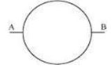
2 A wire of resistance 8R is bent in the form of a circle. What is the effective resistance between the ends of a diameter AB?
3 When electrons drift in a metal from lower to higher potential, does it mean that all the ‘free’ electrons of the metal are moving in the same direction?
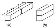
4 Two identical slabs, of a given metal, are joined together, in two different ways, as shown in figures (a) and (b). What is the ratio of the resistances of these two combinations?
5 A cylindrical metallic wire is stretched to increase its length by 5%. Calculate the percentage change in its resistance.
Important Questions for NCERT Class 12 Physics Current Electricity
Question. Two wires of the same metal have same length, but their cross-sections are in the ratio 3 : 1. They are joined in series. The resistance of thicker wire is 10 W. The total resistance of the combination will be
(a) 40Ω
(b) 100 Ω
(c) (5/2) Ω
(d) (40/3) Ω
Answer A
Question. The cold junction of a thermocouple is maintained at 10ºC. No thermo e.m.f. is developed when the hot junction is maintained at 530ºC. The neutral temperature is
(a) 260ºC
(b) 265ºC
(c) 270ºC
(d) 520ºC
Answer C
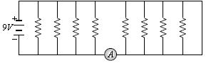
Question. If each resistance in the figure is of 9Ω then reading of ammeter is:
a. 5 A
b. 8 A
c. 2 A
d. 9 A
Answer : A
Question. A wire has resistance 12Ω. It is bent in the form of a circle. The effective resistance between the two points on any diameter is equal to:
a. 12 Ω
b. 6 Ω
c. 3 Ω
d. 24 Ω
Answer : C
Question. You are given several identical resistances each of value R = 10 W and each capable of carrying a maximum current of one ampere. It is required to make a suitable combination of these resistances of 5 W which can carry a current of 4 ampere. The minimum number of resistances of the type R that will be required for this job is
(a) 4
(b) 10
(c) 8
(d) 20
Answer C
Question. 40 electric bulbs are connected in series across a 220 V supply. After one bulb is fused the remaining 39 are connected again in series across the same supply. The illumination will be
(a) more with 40 bulbs than with 39
(b) more with 39 bulbs than with 40
(c) equal in both the cases
(d) in the ratio 402 : 392. .
Answer B
Question. n equal resistors are first connected in series and then connected in parallel. What is the ratio of the maximum to the minimum resistance ?
(a) n
(b) 1/n2
(c) n2
(d) 1/n
Answer C
Question. Two wires of same metal have the same length but their cross sections are in the ratio 3 : 1. They are joined in series. The resistance of the thicker wire is 10 Ω. The total resistance of the combination is
(a) 5/2 Ω
(b) 40/3 Ω
(c) 40 Ω
(d) 100 Ω
Answer C
Question. Consider the following two statements.
(A) Kirchhoff’s junction law follows from the conservation of charge.
(B) Kirchhoff’s loop law follows from the conservation of energy. Which of the following is correct?
(a) Both (A) and (B) are wrong.
(b) (A) is correct and (B) is wrong.
(c) (A) is wrong and (B) is correct.
(d) Both (A) and (B) are correct.
Answer D
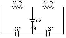
Question. Consider the circuit shown in the figure. The current i3 is equal to:
a. 5 amp
b. 3 amp
c. – 3 amp
d. – 5/6 amp
Answer : D
Question. The scale of a galvanometer of resistance 100Ω contains 25 divisions. It gives a deflection of one division on passing a current of 4 x 10⁻⁴ A. The resistance in ohms to be added to it, so that it may become a voltmeter of range 2.5 volt is:
a. 100
b. 150
c. 250
d. 300
Answer : B
Question. Four wires of the same diameter are connected in turn between two points, maintained at a constant potential difference. Their resistivities are; r and L (wire 1)., 1.2r and 1.2 L (wire 2), 0.9 r and 0.9L (wire 3) and r and 1.5 L (wire 4). Rank the wires according to the rates at which energy is dissipated as heat, greatest first
(a) 4 > 3 > 1 > 2
(b) 4 > 2 > 1 > 3
(c) 1 > 2 > 3 > 4
(d) 3 > 1 > 2 > 4
Answer D
Question. Kirchhoff’s first and second laws of electrical circuits are consequences of
(a) conservation of energy and electric charge respectively
(b) conservation of energy
(c) conservation of electric charge and energy respectively
(d) conservation of electric charge
Answer C.
Question. The electro-chemical equivalent of a substance is numerically equal to the mass of the substance deposited if a current I flows through the electrolyte for 0.25 seconds. The value of I is :
(a) 1 A
(b) 2 A
(c) 3 A
(d) 4 A
Answer D
Question. The equivalent resistance between A and B in the circuit shown will be:
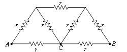
a. (5/4)r
b. (6/5)r
c. (7/6)r
d. (8/7)r
Answer : D
Question. Kirchhoff’s first law, i.e. S i = 0 at a junction, deals with the conservation of
(a) momentum
(b) angular momentum
(c) charge
(d) energy
Answer C
Question. The resistances of the four arms P, Q, R and S in a Wheatstone’s bridge are 10 ohm, 30 ohm, 30 ohm and 90 ohm, respectively. The e.m.f. and internal resistance of the cell are 7 volt and 5 ohm respectively.
If the galvanometer resistance is 50 ohm, the current drawn from the cell will be
(a) 0.1 A
(b) 2.0 A
(c) 1.0 A
(d) 0.2 A
Answer D
Question. The equivalent resistance between points A and B of an infinite network of resistance, each of 1Ω, connected as shown is:
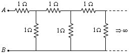
a. Infinite
b. 2 Ω
c. (1 + √5 / 2) Ω
d. Zero
Answer : C
Question. The resistance of a galvanometer is 50 W and current required to give full scale deflection is 100 μA in order to convert it into an ammeter for reading upto 10 A. It is necessary to put an resistance of
(a) 3.5 × 10⁻⁴ Ω
(b) 10 × 10–4 Ω
(c) 2.5 × 10⁻⁴ Ω
(d) 5 × 10⁻⁴ Ω
Answer D
Question. In the given figure, equivalent resistance between A and B will be:
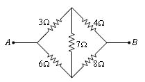
a.(14/3) Ω
b. (3/14) Ω
c. (9/14) Ω
d. (14/9) Ω
Answer : A
Question. In a mixed grouping of identical cells 5 rows are connected in parallel by each row contains 10 cell. This combination send a current i through an external resistance of 20Ω. If the emf and internal resistance of each cell is 1.5 volt and 1 Ω respectively then the value of i is:
a. 0.14
b. 0.25
c. 0.75
d. 0.68
Answer : D
Question. A galvanometer, having a resistance of 50 Ω gives a full scale deflection for a current of 0.05 A. the length in meter of a resistance wire of area of cross-section 2.97 × 10⁻²cm2 that can be used to convert the galvanometer into an ammeter which can read a maximum of 5A current is: (Specific resistance of the wire = 5 × 10⁻⁷ Ωm)
a. 9
b. 6
c. 3
d. 1.5
Answer : C
Question. 100 mA current gives a full scale deflection in a galvanometer of resistance 2Ω. The resistance connected with the galvanometer to convert it into a voltmeter of 5 V range is:
a. 98 Ω
b. 52 Ω
c. 80 Ω
d. 48 Ω
Answer : D
Question. To get maximum current in a resistance of 3 Ω one can use n rows of m cells connected in parallel. If the total no. of cells is 24 and the internal resistance of a cell is 0.5 then:
a. m = 12, n = 2
b. m = 8, n = 4
c. m = 2, n = 12
d. m = 6, n = 4
Answer : A
Question. 100 cells each of emf 5V and internal resistance 1Ω are to be arranged so as to produce maximum current in a 25Ω resistance. Each row contains equal number of cells. The number of rows should be:
a. 2
b. 4
c. 5
d. 100
Answer : A
Question. n identical cells, each of emf E and internal resistance r, are joined in series to form a closed circuit. The potential difference across any one cell is:
a. Zero
b. E
c. E/n
d. (n - 1 / n ) E
Answer : A
Question. In the adjoining circuit, the battery E1 has as emf of 12 volt and zero internal resistance, while the battery E has an emf of 2 volt. If the galvanometer reads zero, then the value of resistance X ohm is:
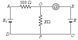
a. 10
b. 100
c. 500
d. 200
Answer : B
Question. A ammeter of range 10 mA has a coil of resistance 1Ω. To use it as voltmeter of range 10 volt, the resistance that must be connected in series with it will be:
a. 999 Ω
b. 99 Ω
c. 1000 Ω
d. None of these
Answer : A
Question. A heating coil is labelled 100 W, 220 V. The coil is cut in half and the two pieces are joined in parallel to the same source. The energy now liberated per second is
(a) 200 W
(b) 400 W
(c) 25 W
(d) 50 W
Answer B
Question. Three resistances each of 4 W are connected to form a triangle. The resistance between any two terminals is
(a) 12 W
(b) 2 W
(c) 6 W
(d) 8/3 W
Answer D
Question. In the following figure ammeter and voltmeter reads 2 amp and 120 volt respectively. Resistance of voltmeter is:
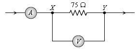
a. 100 #
b. 200 #
c. 300 #
d. 400 #
Answer : C
Section A: Conceptual and Application Type Questions
Question 1. Two wires of equal length, one of copper and the other of manganin have the same resistance. Which wire is thicker?
Answer: The resistance of a conductor is determined by the equation \( R = \rho \frac{l}{A} \). For wires of identical length \( l \) and resistance \( R \), the cross-sectional area \( A \) is directly proportional to the resistivity \( \rho \), which means \( A \propto \rho \). Since manganin has a higher resistivity than copper (\( \rho_{\text{manganin}} > \rho_{\text{copper}} \)), the manganin wire must have a larger cross-sectional area. Therefore, the manganin wire is thicker.
In simple words: Manganin does not let electricity pass as easily as copper. To make their overall resistance equal, the manganin wire has to be thicker than the copper wire.
Exam Tip: Always state the formula \( R = \rho \frac{l}{A} \) and explicitly compare the resistivities of the materials to score full marks.
Question 2. A wire of resistance 8R is bent in the form of a circle. What is the effective resistance between the ends of a diameter AB?
Answer: Bending the wire of total resistance \( 8R \) into a circle divides it into two semi-circular segments across any diameter AB. Each of these semi-circular paths has a resistance of \( 4R \). These two segments are connected in parallel between the points A and B. The effective resistance \( R_{\text{eq}} \) is given by: \[ R_{\text{eq}} = \frac{4R \times 4R}{4R + 4R} = 2R \]
In simple words: When the wire is bent into a circle, the two halves form a parallel circuit. Each half has a resistance of 4R, and combining them in parallel gives a total resistance of 2R.
Exam Tip: Remember that dividing a wire into two equal parallel paths reduces the equivalent resistance to one-quarter of the original wire's resistance.
Question 3. When electrons drift in a metal from lower to higher potential, does it mean that all the ‘free’ electrons of the metal are moving in the same direction?
Answer: No, the free electrons do not all move in the same direction. In the absence of an electric field, electrons move randomly in all directions due to thermal energy. When a potential difference is applied, this random motion continues, but a tiny net drift velocity towards the higher potential is superimposed on top of it. At any given moment, individual electrons are still colliding and moving in various directions, but their overall average position shifts toward the higher potential.
In simple words: Electrons behave like a swarm of bees. They buzz around wildly in all directions, but the whole swarm slowly drifts together in one main direction.
Exam Tip: Be sure to emphasize that the drift velocity is an average value superimposed on the much larger random thermal motion of the electrons.
Question 4. Two identical slabs, of a given metal, are joined together, in two different ways, as shown in figures (a) and (b). What is the ratio of the resistances of these two combinations?
Answer: Let each individual slab have a length \( l \), cross-sectional area \( A \), and resistance \( R = \rho \frac{l}{A} \).
(i) In combination (a), the slabs are connected end-to-end (in series). The total length becomes \( 2l \) and the area remains \( A \). The resistance is: \[ R_a = \rho \frac{2l}{A} = 2R \] (ii) In combination (b), the slabs are connected side-by-side (in parallel). The total cross-sectional area becomes \( 2A \) and the length remains \( l \). The resistance is: \[ R_b = \rho \frac{l}{2A} = \frac{R}{2} \] The ratio of their resistances is: \[ \frac{R_a}{R_b} = \frac{2R}{R/2} = 4 \] Therefore, the ratio is \( 4:1 \).
In simple words: Connecting the blocks end-to-end doubles the resistance, while placing them side-by-side cuts it in half. This makes the first setup four times more resistive than the second.
Exam Tip: Show the step-by-step calculations for both series and parallel configurations to ensure you receive full credit.
Question 5. A cylindrical metallic wire is stretched to increase its length by 5%. Calculate the percentage change in its resistance.
Answer: When a wire is stretched, its volume \( V = A \cdot l \) remains constant. Since \( A = \frac{V}{l} \), we can write resistance as: \[ R = \rho \frac{l}{A} = \rho \frac{l^2}{V} \implies R \propto l^2 \] Let the initial length be \( l \) and the initial resistance be \( R \). The new length after a 5% increase is \( l' = 1.05 l \). The new resistance \( R' \) is: \[ R' \propto (1.05 l)^2 \implies R' = (1.05)^2 R = 1.1025 R \] The percentage change in resistance is: \[ \frac{R' - R}{R} \times 100 = (1.1025 - 1) \times 100 = 10.25\% \]
In simple words: When you stretch a wire, it becomes longer and thinner. This double effect increases the resistance by 10.25% for a 5% increase in length.
Exam Tip: For small percentage changes in length (less than 10%), you can also use the approximation formula \( \frac{\Delta R}{R} \approx 2 \frac{\Delta l}{l} \), but calculating it precisely via \( (1 + x)^2 \) is preferred for safety.
Question 6. A steady current flows in a metallic conductor of non-uniform cross-section. Which of these quantities is constant along the conductor: current, current density, electric field, drift speed?
Answer: Only the **current** remains constant along the conductor. Under steady-state conditions, charge cannot accumulate at any point, so the rate of charge flow (current) must be identical everywhere. Other quantities depend on the cross-sectional area \( A \) and therefore vary along the wire:
- Current density \( J = \frac{I}{A} \) (varies as \( A \) changes)
- Electric field \( E = \rho J \) (varies as \( J \) changes)
- Drift speed \( v_d = \frac{I}{n e A} \) (varies inversely with \( A \))
In simple words: Just like water flowing through a pipe that gets narrower, the total amount of water passing through each section per second stays the same, even though it speeds up in the thin parts.
Exam Tip: Remember that current is a global conservation property, whereas current density, electric field, and drift speed are local properties that depend on geometry.
Question 7. A low voltage supply from which one needs high currents must have very low internal resistance. Why?
Answer: The maximum current that can be drawn from a cell of emf \( E \) and internal resistance \( r \) is given by \( I_{\text{max}} = \frac{E}{r} \). If the voltage supply \( E \) is low, the internal resistance \( r \) must be extremely small to allow a high current \( I \) to flow out of the supply.
In simple words: If a battery has low voltage, it has very little pushing power. If its internal pathway is rough (high resistance), barely any current will make it out.
Exam Tip: Use the maximum current equation \( I_{\text{max}} = \frac{E}{r} \) to justify your explanation mathematically.
Question 8. A high tension (HT) supply of, say, 6 kV must have a very large internal resistance. Why?
Answer: If an accidental short circuit occurs, a high-voltage supply can produce a massive and lethal current. A very large internal resistance limits the maximum short-circuit current \( I_{\text{max}} = \frac{E}{r} \) to a safe, non-lethal value, protecting both the user and the equipment from severe electrical shock or damage.
In simple words: With 6,000 volts, a short circuit would cause a massive, dangerous spark. A high internal resistance acts like a built-in safety brake to keep the current from reaching deadly levels.
Exam Tip: The keyword examiners look for is "limiting the short-circuit current for safety."
Question 9. The electron drift speed is estimated to be only a few mm s–1 for currents in the range of a few amperes? How then is current established almost the instant a circuit is closed?
Answer: Current is not established by a single electron traveling all the way from the source to the load. Instead, closing the circuit immediately sets up an electromagnetic field that propagates through the conductor at nearly the speed of light. This field exerts a force on all free electrons throughout the wire simultaneously, causing them to start drifting at their respective locations almost instantly.
In simple words: It is like a long pipe completely filled with water. The moment you push water in at one end, water immediately starts flowing out of the other end, even though the individual water drops travel slowly.
Exam Tip: Explain this using the propagation of the electromagnetic field at the speed of light to secure full marks.
Question 10. Two conducting wires X and Y of same diameter but different materials are joined in series across a battery. If the number density of electrons in X is twice that in Y, find the ratio of drift velocity of electrons in the two wires?
Answer: When wires are connected in series, the same current \( I \) flows through both. Since they have identical diameters, their cross-sectional areas \( A \) are also equal. The current is related to the drift velocity by the formula: \[ I = n e A v_d \implies v_d \propto \frac{1}{n} \] Given that the electron number density in X is twice that in Y (\( n_X = 2n_Y \)), the ratio of their drift velocities is: \[ \frac{v_{d,X}}{v_{d,Y}} = \frac{n_Y}{n_X} = \frac{1}{2} \] Thus, the ratio of the drift velocity of electrons in wire X to that in wire Y is \( 1:2 \).
In simple words: Since wire X has twice as many free electrons as wire Y, those electrons only need to move half as fast to carry the exact same amount of current.
Exam Tip: State the series condition \( I_X = I_Y \) and the relation \( v_d \propto 1/n \) to make your derivation clear.
Question 11. In an experiment on metre bridge, if the balancing length AJ is ‘l’, what would be its value, when the radius of the metre bridge wire AB is doubled? Justify your answer.
Answer: The balancing length \( l \) will remain exactly the same. The balancing condition of a metre bridge is given by the relation: \[ \frac{R}{S} = \frac{l}{100 - l} \] This ratio depends solely on the lengths of the two segments of the wire and is independent of the wire's cross-sectional area or radius, provided the wire remains uniform along its entire length.
In simple words: Doubling the thickness of the wire lowers the resistance of both sides by the exact same fraction, so the balance point does not move.
Exam Tip: Clearly state that the balancing length is independent of the wire's radius as long as the wire has a uniform cross-section.
Question 12. The sequence of coloured bands in two carbon resistors R1 and R2 is (i) brown, green, blue and (ii) orange, black, green. Find the ratio of their resistances.
Answer: Using the standard carbon resistor color code:
- (i) For resistor \( R_1 \) with bands Brown (1), Green (5), Blue (multiplier \( 10^6 \)): \[ R_1 = 15 \times 10^6 \, \Omega \] - (ii) For resistor \( R_2 \) with bands Orange (3), Black (0), Green (multiplier \( 10^5 \)): \[ R_2 = 30 \times 10^5 \, \Omega = 3 \times 10^6 \, \Omega \] The ratio of their resistances is: \[ \frac{R_1}{R_2} = \frac{15 \times 10^6}{3 \times 10^6} = 5 \] Therefore, the ratio \( R_1 : R_2 \) is \( 5:1 \).
In simple words: The first resistor has a value of 15 million ohms, and the second has a value of 3 million ohms. This makes the first one five times larger than the second.
Exam Tip: Double-check the multiplier values for Blue (\( 10^6 \)) and Green (\( 10^5 \)) as confusing these is a common mistake.
Question 13. The emf of a cell is always greater than its terminal voltage. Why?
Answer: When a cell is in a closed circuit and supplying current \( I \), a portion of its potential is lost across its own internal resistance \( r \). This internal voltage drop is equal to \( I r \). Consequently, the terminal potential difference \( V \) is given by: \[ V = E - I r \] This shows that \( V \) is always less than the electromotive force \( E \) by the value \( I r \). (Note: \( V = E \) only when no current is drawn, i.e., \( I = 0 \)).
In simple words: The battery has to spend a little bit of its own energy just to push the electrical charge through its own internal chemical path, leaving less voltage for the outside circuit.
Exam Tip: Write down the relation \( V = E - Ir \) and define each term to secure full marks.
Question 14. A (i) series (ii) parallel combination of two given resistors is connected, one-by-one, across a cell. In which case will the terminal potential difference, across the cell, have a higher value?
Answer: The terminal potential difference of a cell is given by \( V = E - I r \). To maximize the terminal voltage \( V \), we must minimize the current \( I \) drawn from the cell.
- In a series combination, the total external resistance is larger, which keeps the current \( I \) small.
- In a parallel combination, the total external resistance is smaller, resulting in a larger current \( I \). Therefore, the terminal potential difference will be higher in the **series** combination.
In simple words: The series connection acts like a bottleneck that slows down the current, which prevents the battery from losing too much voltage internally.
Exam Tip: Explain using the relation \( V = E - Ir \), emphasizing that higher external resistance in series minimizes the current \( I \).
Question 15. V- I graph for a metallic wire at two different temperatures T1 and T2 is shown in the figure. Which of the two temperatures is higher and why?
Answer: On an \( I \) versus \( V \) graph, the slope of the line is equal to the reciprocal of the resistance: \[ \text{Slope} = \frac{I}{V} = \frac{1}{R} \] From the graph, the line for temperature \( T_1 \) is steeper than the line for temperature \( T_2 \), meaning: \[ \text{Slope}(T_1) > \text{Slope}(T_2) \implies \frac{1}{R(T_1)} > \frac{1}{R(T_2)} \implies R(T_1) < R(T_2) \] For metallic conductors, the electrical resistance increases as the temperature rises. Since the resistance at \( T_2 \) is larger than at \( T_1 \), the temperature **\( T_2 \)** must be higher than \( T_1 \).
In simple words: The line for T2 shows less current for the same voltage, which means it has a higher resistance. Since metals resist electricity more when they are hot, T2 is the hotter temperature.
Exam Tip: Always pay close attention to the axes of the graph, as a \( V \)- \( I \) graph has a slope of \( R \), while an \( I \)- \( V \) graph has a slope of \( 1/R \).
Question 16. A cell of emf E and internal reistance r is connected across a variable resistor R. Plot a graph showing the variation of terminal potential difference V with resistance R. Predict from the graph the condition under which V becomes equal of E. Also plot a graph showing the variation of \( \varepsilon \) with R.
Answer: The terminal potential difference is given by: \[ V = \frac{E R}{R + r} = \frac{E}{1 + \frac{r}{R}} \] When \( R = 0 \), \( V = 0 \). As \( R \) increases, \( V \) increases asymptotically toward \( E \). The condition under which \( V \) becomes equal to \( E \) is when \( R \to \infty \) (i.e., an open circuit where no current is drawn). The electromotive force \( E \) (or \( \varepsilon \)) of a cell is a constant property of the cell and does not vary with the external resistance \( R \).
In simple words: The terminal voltage starts at zero and curves upward toward the maximum value E as the resistance grows. The cell's built-in voltage E stays constant as a flat horizontal line.
Exam Tip: Label the horizontal asymptote as \( E \) on your graph to show that \( V \) approaches \( E \) as \( R \) becomes extremely large.
Question 17. A heating element is marked 210V, 630W. What is the value of the current drawn by the element when connected to a 210 V DC source?
Answer: Using the electrical power formula \( P = V I \), the current \( I \) can be calculated as: \[ I = \frac{P}{V} = \frac{630}{210} = 3\text{ A} \] The current drawn by the heating element is \( 3\text{ A} \).
In simple words: Divide the power rating of 630 watts by the operating voltage of 210 volts to find that the current is exactly 3 amperes.
Exam Tip: Always include the correct SI unit (A or Ampere) in your final numerical answer to avoid losing marks.
Question 18. Two bulbs of same wattage, one having a carbon filament and the other having a metallic filament, are connected in series to the mains. Which one will glow more?
Answer: When connected in series, the same current \( I \) flows through both bulbs. The power dissipated as heat and light is \( P = I^2 R \). The resistance of carbon (a non-metal/semiconductor) is initially higher than that of a metal filament designed for the same wattage. Furthermore, as temperature increases, the resistance of the carbon filament decreases (negative temperature coefficient), while the resistance of the metallic filament increases (positive temperature coefficient). However, because the carbon filament has a much higher operating resistance than the metallic filament at these currents, it dissipates more power (\( P \propto R \)) and will glow more brightly.
In simple words: Since the bulbs are in series, the one with the higher resistance gets hotter and glows brighter. The carbon filament has a higher resistance than the metal one, so it glows more.
Exam Tip: Be sure to state the relation \( P = I^2 R \) to justify why higher resistance leads to brighter glow in a series connection.
Question 19. Of the bulbs in a house, one glows brighter than the other. Which of the two has a large resistance?
Answer: Household appliances are connected in parallel, which means they all experience the same voltage \( V \). The power consumed is given by the relation: \[ P = \frac{V^2}{R} \implies P \propto \frac{1}{R} \] This means that power (brightness) is inversely proportional to resistance. Therefore, the dimmer bulb has the larger resistance.
In simple words: In a house, everything gets the same voltage. The bulb that glows less brightly is letting less current pass through, which means it has a larger resistance.
Exam Tip: Clearly distinguish between parallel connection (where \( P \propto 1/R \)) and series connection (where \( P \propto R \)).
Question 20. Two electric bulbs of 50W and 100W are given. When they are (i) connected in series (ii) connected in parallel, which bulb will glow more?
Answer: The resistance of a bulb is given by \( R = \frac{V^2}{P} \), meaning resistance is inversely proportional to its rated power. Thus, the \( 50\text{W} \) bulb has twice the resistance of the \( 100\text{W} \) bulb (\( R_{50} > R_{100} \)).
(i) **In series:** The current \( I \) is the same through both bulbs. Since \( P = I^2 R \), the bulb with the larger resistance will dissipate more power. Therefore, the **\( 50\text{W} \)** bulb will glow more.
(ii) **In parallel:** The voltage \( V \) is the same across both bulbs. Since \( P = \frac{V^2}{R} \), the bulb with the smaller resistance will dissipate more power. Therefore, the **\( 100\text{W} \)** bulb will glow more.
In simple words: In a series line, the 50W bulb glows brighter because its higher resistance creates more heat. In a parallel circuit, the 100W bulb glows brighter because it is designed to draw more current.
Exam Tip: Structure your answer clearly by analyzing the series and parallel cases under separate headings.
Question 21. A cell of emf 'E' and internal resistance 'r' is connected across a variable resistor 'R'. Plot a graph showing variation of terminal voltage 'V' of the cell versus the current 'I'. Using the plot, show how the emf of the cell and its internal resistance can be determined.
Answer: The terminal voltage is related to the current by the equation: \[ V = E - I r \] This is a linear equation of the form \( y = m x + c \). Comparing the two, a plot of \( V \) versus \( I \) yields a straight line with a negative slope.
- The vertical intercept (where \( I = 0 \)) gives the Electromotive Force (emf) \( E \) of the cell.
- The magnitude of the slope of the line gives the internal resistance \( r \): \[ \text{Slope} = -r \implies r = |\text{Slope}| \]
In simple words: The graph of voltage against current is a downward-sloping line. The starting point on the vertical axis shows the total EMF, and how steeply the line drops shows the internal resistance.
Exam Tip: Be sure to explicitly state that the slope of this graph represents the negative of the internal resistance (\( \text{Slope} = -r \)).
Question 22. A conductor of length ‘l’ is connected to a dc source of potential ‘V’. If the length of the conductor is tripled by gradually stretching it, keeping ‘V’ constant, how will (i) drift speed of electrons and (ii) resistance of the conductor be affected? Justify your answer.
Answer: (i) The drift velocity is given by the formula \( v_d = \frac{e V \tau}{m l} \). Since the potential difference \( V \) remains constant, drift velocity is inversely proportional to length (\( v_d \propto \frac{1}{l} \)). When the length is tripled (\( 3l \)), the drift velocity becomes **one-third** of its original value.
(ii) The volume of the conductor is constant. When the length is tripled, the cross-sectional area must decrease to one-third of its original value (\( A' = \frac{A}{3} \)). Since resistance is \( R = \rho \frac{l}{A} \), the new resistance is: \[ R' = \rho \frac{3l}{A/3} = 9 \left(\rho \frac{l}{A}\right) = 9 R \] Therefore, the resistance becomes **9 times** the original value.
In simple words: Stretching the wire makes it three times longer and three times thinner. This combined effect increases the resistance nine-fold, while the longer path slows the electron drift speed to a third.
Exam Tip: Remember that stretching a wire to \( n \) times its length always increases its resistance by \( n^2 \) times.
Question 23. Two materials Si and Cu, are cooled from 300 K to 60 K. What will be the effect on their resistivity?
Answer:
- **Silicon (Si)** is a semiconductor. As it is cooled, the thermal energy decreases, causing fewer covalent bonds to break. This drastically reduces the number density of free charge carriers, meaning its resistivity **increases** exponentially.
- **Copper (Cu)** is a metal. As it is cooled, the thermal vibrations of the lattice ions decrease, which reduces the scattering of conduction electrons. This increases the relaxation time \( \tau \), meaning its resistivity **decreases** almost linearly.
In simple words: Cooling silicon freezes its charge carriers in place, making it a poorer conductor. Cooling copper makes its atomic structure calmer, allowing electrons to flow through with less resistance.
Exam Tip: Use the formula \( \rho = \frac{m}{n e^2 \tau} \) to explain that for metals, \( \tau \) dominates, whereas for semiconductors, \( n \) dominates.
Question 24. Plot a graph showing the variation of resistance of a conducting wire as a function of its radius, keeping the length of the wire and its temperature as constant.
Answer: The resistance of a wire is given by: \[ R = \rho \frac{l}{A} = \rho \frac{l}{\pi r^2} \] Since length \( l \) and temperature (and thus resistivity \( \rho \)) are constant, the resistance is inversely proportional to the square of the radius: \[ R \propto \frac{1}{r^2} \] The plot of resistance \( R \) versus radius \( r \) is a hyperbola-like curve that drops rapidly as the radius increases.
In simple words: Making a wire even slightly thicker provides a much wider path for electricity, causing the resistance to drop very quickly.
Exam Tip: Be sure to write the relation \( R \propto 1/r^2 \) next to your curve to show you understand the underlying physics.
Question 25. Two metallic wire of same material have the same length but cross sectional area in the ratio 1:2. They are connected (i) in series and (ii) in parallel. Compare the drift velocities of electrons in the two wires in both cases.
Answer: Let the two wires have cross-sectional areas \( A_1 \) and \( A_2 \), where \( \frac{A_1}{A_2} = \frac{1}{2} \).
(i) **In series:** The current \( I \) is identical in both wires. Using \( I = n e A v_d \), we get \( v_d \propto \frac{1}{A} \). \[ \frac{v_{d1}}{v_{d2}} = \frac{A_2}{A_1} = \frac{2}{1} \] Therefore, the ratio of drift velocities in series is **2:1**.
(ii) **In parallel:** The potential difference \( V \) across both wires is identical. Using \( v_d = \frac{e V \tau}{m l} \), since the length \( l \), voltage \( V \), and material properties (\( \tau \)) are the same, the drift velocity is independent of the cross-sectional area. \[ \frac{v_{d1}}{v_{d2}} = \frac{1}{1} \] Therefore, the ratio of drift velocities in parallel is **1:1**.
In simple words: When connected in series, the same current has to squeeze through the thinner wire, forcing its electrons to move twice as fast. In parallel, they experience the same electrical push over the same distance, so they move at the same speed.
Exam Tip: State the physical parameters that remain constant in each case (current for series, voltage for parallel) to build a solid justification.
Question 26. A potential difference V is applied to a conductor of length L, diameter D. How are the electric field E, drift velocity v and resistance R are affected when (i) V is doubled, (ii) L is doubled, (iii) D is doubled.
Answer: We use the following relationships: \[ E = \frac{V}{L}, \quad v_d = \frac{e V \tau}{m L}, \quad R = \rho \frac{4L}{\pi D^2} \]
(i) **When \( V \) is doubled:**
- Electric field \( E \) is **doubled** (\( E \propto V \)).
- Drift velocity \( v_d \) is **doubled** (\( v_d \propto V \)).
- Resistance \( R \) remains **unaffected** (it depends only on geometry and material).
(ii) **When \( L \) is doubled:**
- Electric field \( E \) becomes **halved** (\( E \propto \frac{1}{L} \)).
- Drift velocity \( v_d \) becomes **halved** (\( v_d \propto \frac{1}{L} \)).
- Resistance \( R \) is **doubled** (\( R \propto L \)).
(iii) **When \( D \) is doubled:**
- Electric field \( E \) remains **unaffected** (independent of \( D \)).
- Drift velocity \( v_d \) remains **unaffected** (independent of \( D \)).
- Resistance \( R \) becomes **one-fourth** of its original value (\( R \propto \frac{1}{D^2} \)).
In simple words: Doubling the voltage pushes harder (doubling field and speed); doubling length stretches the path (halving field and speed, doubling resistance); doubling diameter widens the path (cutting resistance to a quarter).
Exam Tip: Address each parameter (\( E \), \( v_d \), and \( R \)) individually for all three cases to make your answer easy for the examiner to read and grade.
Question 27. Answer the following:
(i) Why are the connections between resistors in a meter bridge made of thick copper strips?
(ii) Why is it generally preferred to obtain the balance point near the middle of the bridge wire in meter bridge experiments?
(iii) Which material is used for the meter bridge wire and why?
Answer:
(i) Thick copper strips have a large cross-sectional area, which makes their electrical resistance negligibly small. This ensures that the resistance of the connections does not affect the measurement of the unknown resistance.
(ii) Obtaining the balance point near the middle of the wire (between 40 cm and 60 cm) ensures that the resistance of all four arms of the Wheatstone bridge is comparable. This maximizes the sensitivity of the bridge and minimizes percentage errors in measuring lengths.
(iii) Constantan or Manganin is used for the bridge wire because these alloys have a high resistivity and a very low temperature coefficient of resistance. This prevents the wire's resistance from changing due to heating during the experiment.
In simple words: We use thick copper to avoid adding extra resistance at junctions, find the balance point in the middle to keep the bridge sensitive and accurate, and use special alloys so the wire's resistance doesn't change when it gets warm.
Exam Tip: Learn these three classic conceptual questions, as they are frequently asked in board practical exams and theory papers alike.
Question 28. A cell of emf (\( \varepsilon \)) and internal resistance (r) is connected across a variable external resistance (R) Plot graphs to show variation of (i) \( \varepsilon \) with R, and (ii) terminal potential difference of the cell (V) with R.
Answer: (i) The electromotive force \( \varepsilon \) is an intrinsic property of the cell and remains constant regardless of the value of the external resistance \( R \). Its plot is a horizontal line.
(ii) The terminal potential difference \( V = \frac{\varepsilon R}{R+r} \) starts at zero when \( R = 0 \) and increases asymptotically toward \( \varepsilon \) as \( R \) increases.
In simple words: The cell's EMF stays flat and constant, while its terminal voltage starts at zero and curves upward, getting closer to the EMF line as the resistance grows.
Exam Tip: Be sure to draw both plots on the same set of axes to highlight how \( V \) approaches \( \varepsilon \) at high values of \( R \).
Section B: Numerical Problems
Question 1. Given the resistances of 1 \( \Omega \), 2 \( \Omega \), 3 \( \Omega \), how will you combine them to get an equivalent resistance of (i) (11/3) \( \Omega \) (ii) (11/5) \( \Omega \), (iii) 6 \( \Omega \), (iv) (6/11) \( \Omega \)?
Answer: Let the three resistances be \( R_1 = 1 \, \Omega \), \( R_2 = 2 \, \Omega \), and \( R_3 = 3 \, \Omega \).
(i) **To get \( \frac{11}{3} \, \Omega \):** Connect \( 1 \, \Omega \) and \( 2 \, \Omega \) in parallel, and then connect this combination in series with \( 3 \, \Omega \). \[ R_{12} = \frac{1 \times 2}{1 + 2} = \frac{2}{3} \, \Omega \] \[ R_{\text{eq}} = R_{12} + R_3 = \frac{2}{3} + 3 = \frac{11}{3} \, \Omega \] (ii) **To get \( \frac{11}{5} \, \Omega \):** Connect \( 2 \, \Omega \) and \( 3 \, \Omega \) in parallel, and then connect this combination in series with \( 1 \, \Omega \). \[ R_{23} = \frac{2 \times 3}{2 + 3} = \frac{6}{5} \, \Omega \] \[ R_{\text{eq}} = R_{23} + R_1 = \frac{6}{5} + 1 = \frac{11}{5} \, \Omega \] (iii) **To get \( 6 \, \Omega \):** Connect all three resistors in series. \[ R_{\text{eq}} = 1 + 2 + 3 = 6 \, \Omega \] (iv) **To get \( \frac{6}{11} \, \Omega \):** Connect all three resistors in parallel. \[ \frac{1}{R_{\text{eq}}} = \frac{1}{1} + \frac{1}{2} + \frac{1}{3} = \frac{6 + 3 + 2}{6} = \frac{11}{6} \implies R_{\text{eq}} = \frac{6}{11} \, \Omega \]
In simple words: By choosing whether to link the resistors in a single chain (series), side-by-side (parallel), or using a mixture of both setups, we can build all four target values.
Exam Tip: Clearly draw small circuit diagrams for each configuration to support your mathematical steps during the exam.
Question 2. (a) Six lead-acid type of secondary cells each of emf 2.0 V and internal resistance 0.015 \( \Omega \) are joined in series to provide a supply to a resistance of 8.5 \( \Omega \). What are the current drawn from the supply and its terminal voltage?
(b) A secondary cell after long use has an emf of 1.9 V and a large internal resistance of 380 \( \Omega \). What maximum current can be drawn from the cell? Could the cell drive the starting motor of a car?
Answer: (a) For six cells in series:
- Total emf \( E_{\text{total}} = 6 \times 2.0 = 12.0\text{ V} \)
- Total internal resistance \( r_{\text{total}} = 6 \times 0.015 = 0.09 \, \Omega \)
- External resistance \( R = 8.5 \, \Omega \) The current drawn is: \[ I = \frac{E_{\text{total}}}{R + r_{\text{total}}} = \frac{12.0}{8.5 + 0.09} = \frac{12.0}{8.59} \approx 1.4\text{ A} \] The terminal voltage is: \[ V = I \times R = 1.397 \times 8.5 \approx 11.9\text{ V} \] (b) For the old cell: The maximum current is drawn when the external resistance is zero: \[ I_{\text{max}} = \frac{E}{r} = \frac{1.9}{380} = 0.005\text{ A} = 5\text{ mA} \] Since a car's starting motor requires a huge current (typically \( 100\text{ A} \) to \( 200\text{ A} \)), this cell **cannot** drive the starting motor of a car.
In simple words: The six batteries in series easily deliver a solid 1.4 amps. However, the old battery has a worn-out internal path that chokes the current down to just 5 milliamperes, which is far too weak to start a car.
Exam Tip: Always state that a starting motor requires a very large current (over 100 A) to fully justify your answer for part (b).
Question 3. Two wires of equal length, one of aluminium and the other of copper have the same resistance. Which of the two wires is lighter? Hence explain why aluminium wires are preferred for overhead power cables. (\( \rho_{\text{Al}} = 2.63 \times 10^{-8} \, \Omega\text{ m} \), \( \rho_{\text{Cu}} = 1.72 \times 10^{-8} \, \Omega\text{ m} \), Relative density of Al = 2.7, of Cu = 8.9.)
Answer: The resistance of a wire is \( R = \rho \frac{l}{A} \implies A = \rho \frac{l}{R} \). The mass of each wire is: \[ m = \text{density} \times \text{volume} = d \times (A \cdot l) = d \times \left(\rho \frac{l}{R}\right) \times l = \frac{d \cdot \rho \cdot l^2}{R} \] Since length \( l \) and resistance \( R \) are the same for both wires: \[ \frac{m_{\text{Al}}}{m_{\text{Cu}}} = \frac{d_{\text{Al}} \cdot \rho_{\text{Al}}}{d_{\text{Cu}} \cdot \rho_{\text{Cu}}} \] Using the given values: \[ \frac{m_{\text{Al}}}{m_{\text{Cu}}} = \frac{2.7 \times 2.63 \times 10^{-8}}{8.9 \times 1.72 \times 10^{-8}} = \frac{7.101}{15.308} \approx 0.46 \] Since this ratio is less than 1, the **aluminium wire is lighter** (having about 46% of the mass of the copper wire).
**Explanation:** Since aluminium is significantly lighter than copper for the same length and resistance, it requires much less structural support (fewer and lighter poles/towers). This makes it the preferred choice for overhead power lines, as it reduces construction costs.
In simple words: An aluminium wire of the same length and resistance weighs less than half as much as a copper wire. This lightness makes it much easier and cheaper to hang from towers over long distances.
Exam Tip: Be sure to write out the ratio of the masses mathematically to clearly prove which metal is lighter.
Question 4. At room temperature (27.0 °C) the resistance of a heating element is 100 \( \Omega \). What is the temperature of the element if the resistance is found to be 117 \( \Omega \), given that the temperature coefficient of the material of the resistor is \( 1.70 \times 10^{-4} \, \text{°C}^{-1} \).
Answer: The temperature dependence of resistance is described by the equation: \[ R(T) = R_0 [1 + \alpha (T - T_0)] \implies T - T_0 = \frac{R(T) - R_0}{R_0 \cdot \alpha} \] Given:
- Initial resistance \( R_0 = 100 \, \Omega \) at temperature \( T_0 = 27.0\text{ °C} \)
- Final resistance \( R(T) = 117 \, \Omega \)
- Coefficient \( \alpha = 1.70 \times 10^{-4}\text{ °C}^{-1} \) Substituting these values: \[ T - 27.0 = \frac{117 - 100}{100 \times 1.70 \times 10^{-4}} = \frac{17}{0.017} = 1000\text{ °C} \] \[ T = 1000 + 27.0 = 1027\text{ °C} \] The temperature of the element is \( 1027\text{ °C} \).
In simple words: As the heating element warms up, its resistance climbs. To go from 100 to 117 ohms, the temperature has to rise by 1000 degrees, reaching 1027 degrees Celsius.
Exam Tip: Pay close attention to your decimal points when working with small values of \( \alpha \) to avoid simple arithmetic mistakes.
Question 5. (a) In a metre bridge, the balance point is found to be at 39.5 cm from the end A, when the resistor Y is of 12.5 \( \Omega \). Determine the resistance of X. Why are the connections between resistors in a Wheatstone or meter bridge made of thick copper strips?
(b) Determine the balance point of the bridge above if X and Y are interchanged.
(c) What happens if the galvanometer and cell are interchanged at the balance point of the bridge? Would the galvanometer show any current?
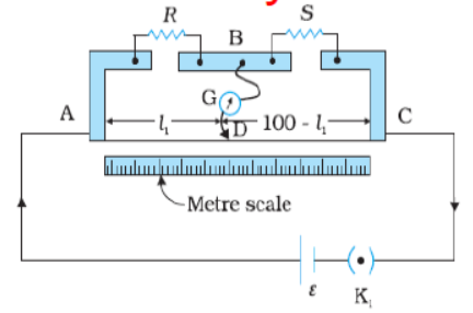
Answer: (a) The bridge balance equation is: \[ \frac{X}{Y} = \frac{l}{100 - l} \implies X = Y \left(\frac{l}{100 - l}\right) \] Substitute \( Y = 12.5 \, \Omega \) and \( l = 39.5\text{ cm} \): \[ X = 12.5 \times \frac{39.5}{100 - 39.5} = 12.5 \times \frac{39.5}{60.5} \approx 8.16 \, \Omega \] The connections are made of thick copper strips to minimize their resistance, ensuring they do not affect the measured balance point.
(b) If X and Y are interchanged, the balancing length \( l' \) from end A is: \[ l' = 100 - l = 100 - 39.5 = 60.5\text{ cm} \] (c) If the galvanometer and cell are interchanged at the balance point, the balance condition remains completely unaffected. The galvanometer will still show **no current** (zero deflection).
In simple words: The unknown resistor X is 8.16 ohms. Interchanging the resistors simply mirrors the balance point to the other side at 60.5 cm. Swapping the battery and the galvanometer doesn't disturb the balance of the system at all.
Exam Tip: Always clearly state that interchanging the cell and galvanometer does not affect the balance condition due to the symmetry of the Wheatstone bridge circuit.
Question 6. Two students ‘X’ and ‘Y’ perform an experiment on potentiometer separately using the circuit given: Keeping other parameters unchanged, how will the position of the null point be affected if (i) ‘X’ increases the value of resistance R in the set-up by keeping the key K1 closed and the key K2 open? (ii) ‘Y’ decreases the value of resistance S in the set-up, while the key K2 remain open and the key K1 closed? Justify.
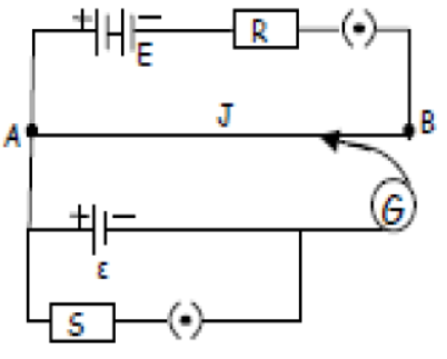
Answer:
(i) Increasing the resistance \( R \) in the primary circuit reduces the current flowing through the potentiometer wire AB. This decreases the potential gradient \( k \) along the wire. Since the balance length is given by \( l = \frac{E}{k} \), a decrease in \( k \) causes the balance length \( l \) to **increase** (meaning the null point shifts towards end B).
(ii) Since the key \( K_2 \) remains open, the resistor \( S \) is disconnected from the secondary circuit. Because no current flows through \( S \), changing its value has **no effect** on the position of the null point.
In simple words: Adding resistance in the main circuit weakens the electrical push along the wire, so we need a longer stretch of wire to balance the cell. Adjusting the secondary resistor while its switch is open does absolutely nothing because it is not connected to the circuit.
Exam Tip: Be sure to explicitly point out that because K2 is open, no current flows through S, meaning it plays no role in the circuit's behavior.
Question 7. Calculate the value of the current drawn from a 5 V battery in the circuit as shown.
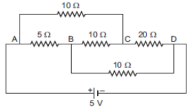
Answer: The circuit acts as a balanced Wheatstone bridge. Let us check the ratio of resistances: \[ \frac{R_{AB}}{R_{BD}} = \frac{5}{10} = \frac{1}{2} \] \[ \frac{R_{AC}}{R_{CD}} = \frac{10}{20} = \frac{1}{2} \] Since these ratios are equal, the bridge is balanced. Consequently, no current flows through the diagonal \( 10 \, \Omega \) resistor connected between points B and C, so it can be removed from our calculations. The remaining network consists of two parallel branches connected across the 5 V battery:
- Upper branch ABD: \( R_1 = 5 + 10 = 15 \, \Omega \)
- Lower branch ACD: \( R_2 = 10 + 20 = 30 \, \Omega \) The equivalent resistance \( R_{\text{eq}} \) of these parallel branches is: \[ R_{\text{eq}} = \frac{15 \times 30}{15 + 30} = \frac{450}{45} = 10 \, \Omega \] The total current drawn from the battery is: \[ I = \frac{V}{R_{\text{eq}}} = \frac{5}{10} = 0.5\text{ A} \]
In simple words: The circuit is a balanced bridge, meaning we can ignore the middle 10-ohm resistor. This simplifies the circuit to a 15-ohm path and a 30-ohm path in parallel, giving a total resistance of 10 ohms and a current of 0.5 amperes.
Exam Tip: Always show that the bridge is balanced by demonstrating that \( \frac{P}{Q} = \frac{R}{S} \) before removing the central resistor.
Question 8. In the figure a long uniform potentiometer wire AB is having a constant potential gradient along its length. The null points for the two primary cells of emfs \( \varepsilon_1 \) and \( \varepsilon_2 \) connected in the manner shown are obtained at a distance of 120 cm and 300 cm from the end A. Find (i) \( \varepsilon_1 / \varepsilon_2 \) and (ii) position of null point for the cell \( \varepsilon_1 \). How is the sensitivity of a potentiometer increased?
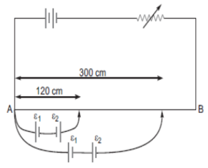
Answer: Let \( k \) be the potential gradient along the potentiometer wire.
- When the cells assist each other (series aiding): \[ \varepsilon_1 + \varepsilon_2 = k \times 300 \quad \text{--- (1)} \] - When the cells oppose each other (series opposing): \[ \varepsilon_1 - \varepsilon_2 = k \times 120 \quad \text{--- (2)} \] Adding equations (1) and (2): \[ 2 \varepsilon_1 = 420 k \implies \varepsilon_1 = 210 k \] Substituting this into equation (1): \[ 210 k + \varepsilon_2 = 300 k \implies \varepsilon_2 = 90 k \]
(i) The ratio of the emfs is: \[ \frac{\varepsilon_1}{\varepsilon_2} = \frac{210 k}{90 k} = \frac{7}{3} \] (ii) The position of the null point for cell \( \varepsilon_1 \) alone is: \[ l_1 = \frac{\varepsilon_1}{k} = 210\text{ cm} \] The sensitivity of a potentiometer can be increased by reducing its potential gradient \( k \). This can be achieved by:
- Increasing the length of the potentiometer wire.
- Decreasing the current in the primary circuit by adding resistance in series with the driver cell.
In simple words: The two cells together balance at 300 cm, but when they oppose each other, they balance at 120 cm. This tells us the first cell alone balances at 210 cm, and its voltage is 7/3 times larger than the second cell.
Exam Tip: Show both the aiding and opposing algebraic equations clearly to make your derivation easy to follow.
Question 9. A cell of emf E and internal resistance r is connected to two external resistances R1 and R2 and a perfect ammeter. The current in the circuit is measured in four different situations:
(i) without any external resistance in the circuit.
(ii) with resistance R1 only
(iii) with R1 and R2 in series combination
(iv) with R1 and R2 in parallel combination.
The currents measured in the four cases are 0.42 A, 1.05 A, 1.4 A and 4.2 A, but not necessarily in that order. Identify the currents corresponding to the four cases mentioned above.
Answer: The current in the circuit is given by \( I = \frac{E}{R_{\text{total}}} \), which means that a larger total resistance results in a smaller current. Let us rank the external resistances for the four cases:
- Case (i) Short circuit (no external resistance): \( R = 0 \) (minimum resistance).
- Case (iii) Series combination: \( R = R_1 + R_2 \) (maximum resistance).
- Since the parallel resistance \( R_p = \frac{R_1 R_2}{R_1 + R_2} \) is smaller than the individual resistance \( R_1 \), we have: \[ 0 < R_{\text{parallel}} < R_1 < R_{\text{series}} \] Adding the internal resistance \( r \) to each, the total resistance of the circuit ranks as: \[ r < r + R_{\text{parallel}} < r + R_1 < r + R_{\text{series}} \] Therefore, the corresponding currents rank in reverse order: \[ I_{\text{short}} > I_{\text{parallel}} > I_{\text{single}} > I_{\text{series}} \] Matching these to the given currents (4.2 A, 1.4 A, 1.05 A, 0.42 A):
- **(i) Without any external resistance:** **4.2 A**
- **(iv) with parallel combination:** **1.4 A**
- **(ii) with \( R_1 \) only:** **1.05 A**
- **(iii) with series combination:** **0.42 A**
In simple words: The current is highest when there is no resistance, and lowest when the resistors are in series. Parallel connection has less resistance than a single resistor, so its current is the second highest.
Exam Tip: Be sure to write down the inequality chain comparing the resistances of the four setups to make your reasoning airtight.
Question 10. A straight line plot showing the terminal potential difference (V) of a cell as a function of current (I) drawn from it is shown in the figure. Using this plot, determine (i) the emf and (ii) internal resistance of the cell.
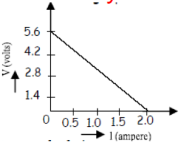
Answer: The relationship between terminal potential difference and current is given by: \[ V = E - I r \] (i) When the current \( I = 0 \), the terminal potential difference \( V \) is equal to the electromotive force \( E \). From the graph, the y-intercept (potential value at \( I = 0 \)) is: \[ E = 5.6\text{ V} \] Therefore, the emf of the cell is **5.6 V**.
(ii) When the terminal potential difference \( V = 0 \), the current is at its maximum \( I = 2.0\text{ A} \). Substituting these values: \[ 0 = E - I_{\text{max}} \cdot r \implies r = \frac{E}{I_{\text{max}}} = \frac{5.6}{2.0} = 2.8 \, \Omega \] Therefore, the internal resistance of the cell is **2.8 \( \Omega \)**.
In simple words: The starting point on the vertical axis shows that the cell's maximum potential is 5.6 volts. The slope of the line shows that its internal pathway has a resistance of 2.8 ohms.
Exam Tip: Always note the intercept values on both axes to quickly determine \( E \) and \( I_{\text{max}} \).
Question 11. Using Kirchoff’s rule, find the currents \( I_1, I_2 \) and \( I_3 \).
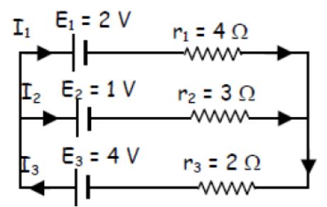
Answer: Let us apply nodal analysis at the left junction (node A). Let the potential of the right junction be the reference ground (\( V_B = 0 \)) and let the potential at node A be \( V_A \). The currents flowing from right to left in the three parallel branches are: \[ I_1 = \frac{E_1 - V_A}{r_1} = \frac{2 - V_A}{4} \] \[ I_2 = \frac{E_2 - V_A}{r_2} = \frac{1 - V_A}{3} \] \[ I_3 = \frac{E_3 - V_A}{r_3} = \frac{4 - V_A}{2} \] According to Kirchhoff's Current Law, the sum of these currents at junction A is zero: \[ I_1 + I_2 + I_3 = 0 \implies \frac{2 - V_A}{4} + \frac{1 - V_A}{3} + \frac{4 - V_A}{2} = 0 \] Multiplying the entire equation by the LCM of 12: \[ 3(2 - V_A) + 4(1 - V_A) + 6(4 - V_A) = 0 \] \[ 6 - 3V_A + 4 - 4V_A + 24 - 6V_A = 0 \implies 34 - 13V_A = 0 \implies V_A = \frac{34}{13}\text{ V} \] Now, we calculate each individual current: \[ I_1 = \frac{2 - 34/13}{4} = \frac{-8}{52} = -\frac{2}{13}\text{ A} \approx -0.15\text{ A} \] \[ I_2 = \frac{1 - 34/13}{3} = \frac{-21}{39} = -\frac{7}{13}\text{ A} \approx -0.54\text{ A} \] \[ I_3 = \frac{4 - 34/13}{2} = \frac{18}{26} = \frac{9}{13}\text{ A} \approx 0.69\text{ A} \] The negative values for \( I_1 \) and \( I_2 \) indicate that these currents actually flow in the direction opposite to the arrows (from left to right).
In simple words: By finding the electrical potential at the junction, we calculate that the currents are -2/13 A, -7/13 A, and 9/13 A. The negative signs just mean the electricity is flowing the other way.
Exam Tip: Be sure to write a brief sentence explaining what negative current values mean to demonstrate a clear grasp of the physics.
Question 12. State Kirchhoff’s rules. Apply Kirchhoff’s rules to the loops ACBPA and ACBQA to write the expressions for the currents \( I_1, I_2 \) and \( I_3 \) in the network.
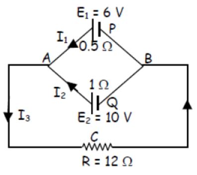
Answer: **Kirchhoff's Rules:**
1. **Junction Rule (Current Law - KCL):** The sum of all currents entering a junction is equal to the sum of all currents leaving that junction (\( \sum I = 0 \)). This is a statement of the conservation of charge.
2. **Loop Rule (Voltage Law - KVL):** The algebraic sum of changes in potential around any closed loop is zero (\( \sum \Delta V = 0 \)). This is a statement of the conservation of energy.
**Applying to the Network:** At junction A, the current relationship is: \[ I_3 = I_1 + I_2 \quad \text{--- (1)} \] Applying the loop rule to the closed loop **ACBPA** (counter-clockwise): \[ -I_3 R - I_1 r_1 + E_1 = 0 \implies 12 I_3 + 0.5 I_1 = 6 \] Substituting \( I_3 \) from equation (1): \[ 12.5 I_1 + 12 I_2 = 6 \quad \text{--- (2)} \] Applying the loop rule to the closed loop **ACBQA** (counter-clockwise): \[ -I_3 R - I_2 r_2 + E_2 = 0 \implies 12 I_3 + 1 I_2 = 10 \] Substituting \( I_3 \) from equation (1): \[ 12 I_1 + 13 I_2 = 10 \quad \text{--- (3)} \] Equations (2) and (3) are the required loop expressions.
In simple words: The first rule says what goes in must come out, and the second rule says the voltage gains and drops around any loop must balance to zero. Using these, we get two simple equations relating the currents.
Exam Tip: Always state the physical conservation law behind each rule (charge for the first, energy for the second) to ensure full credit.
Question 13. For the circuit shown here, calculate the potential difference between the points B and D.
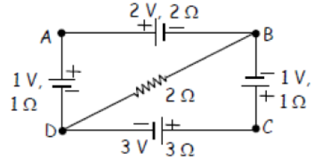
Answer: Let us apply Kirchhoff's Voltage Law to the circuit. Let the current flowing in the upper loop (mesh BADB) be \( i - i_1 \) and the current in the lower loop (mesh DCBD) be \( i \). Applying KVL to mesh **BADB**: \[ -2(i - i_1) + 2 - 1 - 1(i - i_1) + 2i_1 = 0 \implies 3i - 5i_1 = 1 \quad \text{--- (1)} \] Applying KVL to mesh **DCBD**: \[ -3i + 3 - 1 - 1i - 2i_1 = 0 \implies 4i + 2i_1 = 2 \implies 2i + i_1 = 1 \quad \text{--- (2)} \] Multiplying equation (2) by 5 and adding it to equation (1): \[ 10i + 5i_1 = 5 \] \[ (3i - 5i_1) + (10i + 5i_1) = 1 + 5 \implies 13i = 6 \implies i = \frac{6}{13}\text{ A} \] Substituting \( i \) into equation (2): \[ 2 \left(\frac{6}{13}\right) + i_1 = 1 \implies i_1 = 1 - \frac{12}{13} = \frac{1}{13}\text{ A} \] The potential difference between points B and D is the potential drop across the diagonal resistor: \[ V_B - V_D = i_1 \times 2 = \frac{1}{13} \times 2 = \frac{2}{13}\text{ V} \approx 0.15\text{ V} \]
In simple words: By writing down loop equations for both halves of the circuit, we calculate that the current through the diagonal path is 1/13 of an ampere. This creates a potential difference of 2/13 of a volt between B and D.
Exam Tip: Be careful with the signs when writing down KVL equations, paying close attention to which way the battery terminals are facing.
Question 14. The plot of the variation of potential difference across a combination of three identical cells in series versus current is as shown below. What is the emf of each cell?
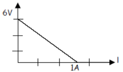
Answer: For three identical cells connected in series, the total terminal voltage \( V \) is given by: \[ V = E_{\text{total}} - I r_{\text{total}} = 3E - 3Ir \] When no current is drawn (\( I = 0 \)), the terminal voltage is equal to the total electromotive force of the series combination. From the graph, the y-intercept (the potential value at \( I = 0 \)) is: \[ E_{\text{total}} = 6\text{ V} \] Since there are three identical cells in series: \[ 3E = 6\text{ V} \implies E = \frac{6}{3} = 2\text{ V} \] The emf of each cell is **2 V**.
In simple words: The graph shows that the three batteries together produce 6 volts when no current is flowing. Since they are identical and in series, we divide 6 by 3 to find that each battery has an EMF of 2 volts.
Exam Tip: Always state that the y-intercept represents the open-circuit voltage (or total emf) of the combination before dividing by the number of cells.
Question 15. In the circuit of fig. a metre bridge is shown in its balanced state. The metre bridge wire has a resistance of 1 ohm/cm. Calculate the value of the unknown resistance X and the current drawn from the battery of negligible internal resistance.
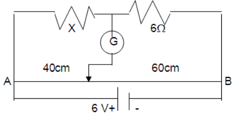
Answer:
**1. Finding Unknown Resistance X:** Using the balancing condition of the metre bridge: \[ \frac{X}{6} = \frac{l}{100 - l} \] Given that the balancing length is \( l = 40\text{ cm} \): \[ \frac{X}{6} = \frac{40}{60} \implies X = 6 \times \frac{2}{3} = 4 \, \Omega \] **2. Finding Current Drawn from the Battery:** The total resistance of the bridge wire of length 100 cm is: \[ R_{\text{wire}} = 100\text{ cm} \times 1 \, \Omega/\text{cm} = 100 \, \Omega \] The upper branch contains the resistors \( X = 4 \, \Omega \) and \( 6 \, \Omega \) in series: \[ R_{\text{upper}} = 4 + 6 = 10 \, \Omega \] These two branches are in parallel across the 6 V battery. The equivalent resistance of the circuit is: \[ R_{\text{eq}} = \frac{R_{\text{upper}} \times R_{\text{wire}}}{R_{\text{upper}} + R_{\text{wire}}} = \frac{10 \times 100}{10 + 100} = \frac{1000}{110} = \frac{100}{11} \, \Omega \] The total current drawn from the 6 V battery is: \[ I = \frac{V}{R_{\text{eq}}} = \frac{6}{100/11} = \frac{66}{100} = 0.66\text{ A} \]
In simple words: First, the balance point tells us that X is 4 ohms. Next, we find the resistance of the parallel paths (10 ohms and 100 ohms) to get an overall resistance of 9.09 ohms, which draws a current of 0.66 amperes from the battery.
Exam Tip: Don't forget to include the resistance of the bridge wire when calculating the total equivalent resistance of the circuit.
Question 16. Find the value of the unknown resistance X in the circuit of fig. if no current flows through the section AO. Also calculate the current drawn by the circuit from the battery of emf 6 V and negligible internal resistance.
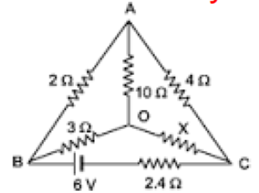
Answer:
**1. Finding Unknown Resistance X:** Since no current flows through the branch AO, the circuit acts as a balanced Wheatstone bridge. \[ \frac{R_{AB}}{R_{BO}} = \frac{R_{AC}}{R_{OC}} \implies \frac{2}{3} = \frac{4}{X} \implies X = 6 \, \Omega \] **2. Finding Current Drawn from the Battery:** Because branch AO is inactive, we can remove the \( 10 \, \Omega \) resistor from our calculations.
- The upper series path has resistance: \( R_{\text{upper}} = 2 + 4 = 6 \, \Omega \)
- The lower series path has resistance: \( R_{\text{lower}} = 3 + X = 3 + 6 = 9 \, \Omega \) The equivalent parallel resistance of these two paths is: \[ R_{\text{parallel}} = \frac{6 \times 9}{6 + 9} = \frac{54}{15} = 3.6 \, \Omega \] This combination is in series with the external resistor \( R_{\text{ext}} = 2.4 \, \Omega \). The total equivalent resistance of the circuit is: \[ R_{\text{total}} = 3.6 + 2.4 = 6.0 \, \Omega \] The total current drawn from the 6 V battery is: \[ I = \frac{V}{R_{\text{total}}} = \frac{6}{6} = 1\text{ A} \]
In simple words: The balanced bridge gives X a value of 6 ohms. Removing the inactive middle branch simplifies the circuit to parallel paths of 6 and 9 ohms, which combine with the 2.4-ohm resistor to give a total of 6 ohms and draw exactly 1 ampere.
Exam Tip: Be sure to add the series resistor (2.4 \( \Omega \)) after resolving the parallel Wheatstone bridge section to find the correct total resistance.
Question 17. A potentiometer wire of length 1 m is connected to a driver cell of emf 3 V as shown in the figure. When a cell of 1.5 V emf is used in the secondary circuit, the balance point is found to be 60 cm. On replacing this cell and using a cell of unknown emf, the balance point shifts to 80 cm.
(i) Calculate unknown emf of the cell.
(ii) Explain with reason, whether the circuit works, if the driver cell is replaced with a cell of emf 1 V.
(iii) Does the high resistance R, used in the secondary circuit affect the balance point? Justify your answer
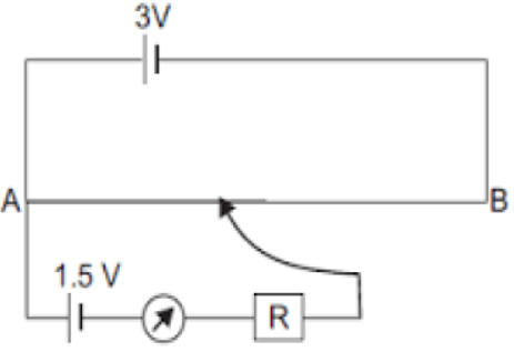
Answer:
(i) Since the potential gradient remains constant: \[ \frac{E_1}{E_2} = \frac{l_1}{l_2} \implies \frac{1.5}{E_2} = \frac{60}{80} \implies E_2 = 1.5 \times \frac{80}{60} = 2.0\text{ V} \] The unknown emf is **2.0 V**.
(ii) The circuit will **not work** if the driver cell is replaced with a 1 V cell. The emf of the driver cell must always be greater than the emf of any cell being measured in the secondary circuit. With a 1 V driver cell, the maximum potential drop across the wire is only 1 V, which cannot balance a 1.5 V or 2.0 V cell.
(iii) No, the high resistance \( R \) in the secondary circuit **does not affect** the balance point. At the balance point, no current flows through the galvanometer branch, meaning there is zero potential drop across \( R \). Its only purpose is to protect the galvanometer from high currents before the balance point is reached.
In simple words: The unknown cell has an EMF of 2.0 volts. The circuit won't work with a 1-volt driver because you can't measure 1.5 or 2 volts if your scale only goes up to 1 volt. The safety resistor doesn't change the balance point because no current flows through it at balance.
Exam Tip: Remember that the driver cell's voltage must always exceed the voltage of the cell being measured, or else you will never find a balance point on the wire.
Question 18. A 10 m long wire of uniform cross-section and 20 \( \Omega \) resistance is used in a potentiometer. The wire is connected in series with a battery of 5 V along with an external resistance of 480 \( \Omega \). If an unknown emf E is balanced at 6.0 m length of the wire calculate
(i) the potential gradient of the potentiometer wire, (ii) the value of unknown emf.
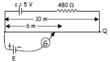
Answer:
- Total resistance of the primary circuit is: \[ R_{\text{total}} = R_{\text{wire}} + R_{\text{ext}} = 20 + 480 = 500 \, \Omega \] - The current in the primary circuit is: \[ I = \frac{V_{\text{driver}}}{R_{\text{total}}} = \frac{5}{500} = 0.01\text{ A} \] - The potential drop across the 10 m wire is: \[ V_{\text{wire}} = I \times R_{\text{wire}} = 0.01 \times 20 = 0.2\text{ V} \]
(i) The potential gradient \( k \) along the wire is: \[ k = \frac{V_{\text{wire}}}{L} = \frac{0.2\text{ V}}{10\text{ m}} = 0.02\text{ V/m} \] (ii) The unknown emf \( E \) balanced at \( l = 6.0\text{ m} \) is: \[ E = k \times l = 0.02 \times 6.0 = 0.12\text{ V} \]
In simple words: The primary circuit sends a small current that creates a potential drop of 0.2 volts across the 10-meter wire, giving a gradient of 0.02 volts per meter. A balance point at 6 meters means the unknown EMF is 0.12 volts.
Exam Tip: Always calculate the actual voltage drop across the wire (\( V_{\text{wire}} \)) first, rather than using the driver cell's total voltage directly, as some voltage is lost across the series resistor.
Question 19. Potentiometer wire PQ of 1 m length is connected to a standard cell E1. Another cell E2 of emf 1.02 V is connected as shown in the circuit diagram with a resistance ‘r’ and switch S. With switch S open, null position is obtained at a distance of 51 cm from P. Calculate (i) potential gradient of the potentiometer wire and (ii) emf of the cell E1. (iii) When switch S is closed, will null point towards P or towards Q? Give reason for your answer.
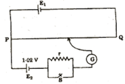
Answer:
(i) With switch S open, the balancing length for cell \( E_2 = 1.02\text{ V} \) is \( l = 51\text{ cm} \). The potential gradient \( k \) is: \[ k = \frac{E_2}{l} = \frac{1.02\text{ V}}{51\text{ cm}} = 0.02\text{ V/cm} = 2.0\text{ V/m} \] (ii) Assuming the standard cell \( E_1 \) has negligible internal resistance, the total potential drop across the 100 cm wire PQ is equal to the emf of \( E_1 \): \[ E_1 = k \times L = 0.02\text{ V/cm} \times 100\text{ cm} = 2.0\text{ V} \] (iii) When the switch S is closed, current is drawn from the cell \( E_2 \) through the resistor \( r \). This means we are now balancing its terminal voltage \( V = E_2 - I r \), which is less than the open-circuit emf \( E_2 \). Since the balanced voltage is smaller, the balancing length will also be shorter, causing the null point to shift **towards P** (closer to the zero end).
In simple words: The wire has a potential gradient of 0.02 volts per centimeter, making the driver cell's voltage 2.0 volts. Closing the switch draws current from the test cell and lowers its terminal voltage, shortening the balance length toward P.
Exam Tip: For part (iii), use the terminal voltage equation \( V = E - Ir \) to show why closing the switch always reduces the voltage being balanced.
Question 20. For the potentiometer circuit shown in the given figure, points X and Y represent the two terminals of an unknown emf \( \varepsilon \). A student observed that when the jockey is moved from the end A to the end B of the potentiometer wire, the direction of the deflection in the galvanometer remains in the same direction. What may be the two possible faults in the circuit that could result in this observations? If the galvanometer deflection at the end B is (i) more, (ii) less, than that at the end A which of the two faults, listed above, would be there in the circuit? Give reasons in support of your answer in each case.
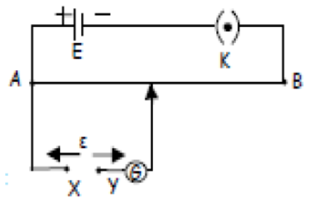
Answer: The two possible faults that can cause the galvanometer to deflect in only one direction along the entire wire are:
1. **Fault 1:** The positive terminal of the unknown cell \( \varepsilon \) is connected in reverse (it is connected to B instead of the end A).
2. **Fault 2:** The emf of the driver cell \( E \) is smaller than the unknown emf \( \varepsilon \) (\( E < \varepsilon \)), meaning the potential drop across wire AB is too small to balance \( \varepsilon \).
Let us analyze the behavior in each case:
- **(i) Deflection at B is more than at A:** This is caused by **Fault 1** (reversed polarity). In this case, the potential difference along the wire AJ acts in the same direction as the cell \( \varepsilon \) instead of opposing it. As the jockey moves towards B, the aiding voltage increases, leading to a larger current and greater deflection.
- **(ii) Deflection at B is less than at A:** This is caused by **Fault 2** (\( E < \varepsilon \)). Here, the polarities are correct, so the wire's potential drop opposes the cell \( \varepsilon \). As the jockey moves towards B, the opposing voltage increases, which decreases the net voltage and reduces the deflection, although it never drops to zero.
In simple words: If the deflection increases toward B, the cell is connected backward, causing the wire's voltage to add to the cell instead of opposing it. If the deflection decreases toward B, the setup is correct, but the driver battery is simply too weak to balance the test cell.
Exam Tip: Be sure to explain the physical direction of the potential differences (aiding vs. opposing) to make your reasoning easy for the examiner to follow.
Question 21. The storage battery of a car has an emf of 12 V. If the internal resistance of the battery is 0.4 \( \Omega \), what is the maximum current that can be drawn from the battery?
Answer: The maximum current is drawn from a battery when the external resistance connected to it is zero: \[ I_{\text{max}} = \frac{E}{r} = \frac{12}{0.4} = 30\text{ A} \] The maximum current that can be drawn is \( 30\text{ A} \).
In simple words: Divide the battery's EMF of 12 volts by its internal resistance of 0.4 ohms to find that the maximum possible current is 30 amperes.
Exam Tip: Note that drawing the maximum current (\( I_{\text{max}} = E/r \)) is a short-circuit condition where the terminal voltage drops to zero.
Question 22. A battery of emf 10 V and internal resistance 3 \( \Omega \) is connected to a resistor. If the current in the circuit is 0.5 A, what is the resistance of the resistor? What is the terminal voltage of the battery when the circuit is closed?
Answer:
**1. Finding Resistance of the Resistor R:** Using Ohm's Law for the complete circuit: \[ I = \frac{E}{R + r} \implies 0.5 = \frac{10}{R + 3} \] \[ R + 3 = \frac{10}{0.5} = 20 \implies R = 17 \, \Omega \] **2. Finding Terminal Voltage V:** The terminal voltage is: \[ V = E - I r = 10 - (0.5 \times 3) = 10 - 1.5 = 8.5\text{ V} \] Alternatively, using the external load: \[ V = I \times R = 0.5 \times 17 = 8.5\text{ V} \] The resistance of the resistor is \( 17 \, \Omega \) and the terminal voltage is \( 8.5\text{ V} \).
In simple words: The current of 0.5 amperes shows that the total resistance is 20 ohms, meaning the resistor has a value of 17 ohms. The battery loses 1.5 volts internally, leaving 8.5 volts at its terminals.
Exam Tip: You can calculate the terminal voltage using either \( V = E - Ir \) or \( V = IR \) as a quick way to double-check your arithmetic.
Free study material for Physics
CBSE Class 12 Physics Worksheets for Chapter 03 Current Electricity
Download Chapter Worksheets: Class 12 Physics
Review targeted practice exercises for Class 12 Physics Chapter 03 Current Electricity. Curated to match official CBSE guidelines, these printable problem sets support daily revision and improve overall test readiness.
Concept Clarification for Chapter 03 Current Electricity
Designed around the official curriculum for Class 12 Physics, these practice sheets guarantee standard compliance. Reviewing step-by-step solutions after completion sharpens your accuracy and clarifies complex sub-topics within Chapter 03 Current Electricity.
Effective Revision Strategies for School Exams
Follow up your worksheet practice by attempting the interactive online MCQ tests for Chapter 03 Current Electricity to evaluate your execution speed. All printable assignments and revision sheets on our platform are updated for the 2026 session and available free of charge.
FAQs
You can download the latest chapter-wise printable worksheets for Class 12 Physics Chapter 03 Current Electricity for free from StudiesToday.com. These have been made as per the latest CBSE curriculum for this academic year.
Yes, Class 12 Physics worksheets for Chapter 03 Current Electricity focus on activity-based learning and also competency-style questions. This helps students to apply theoretical knowledge to practical scenarios.
Yes, we have provided solved worksheets for Class 12 Physics Chapter 03 Current Electricity to help students verify their answers instantly.
Yes, our Class 12 Physics test sheets are mobile-friendly PDFs and can be printed by teachers for classroom.
For Chapter 03 Current Electricity, regular practice with our worksheets will improve question-handling speed and help students understand all technical terms and diagrams.