

Chapter-wise Worksheets for Class 12 Physics: Electric Potential And Capacitance
Review targeted academic worksheets with the CBSE Class 12 Physics Electric Potential And Capacitance Worksheet. Built according to official educational standards for the 2026-27 term, these downloadable Class 12 Physics resources support effective daily practice and detailed self-evaluation for Electric Potential And Capacitance.
Practice Class 12 Physics Worksheets: Electric Potential And Capacitance
Navigate directly to the solved Physics worksheets using the digital viewer below. Each practice set includes detailed step-by-step solutions, allowing students to instantly cross-check their work and identify areas requiring further revision.
Electric Potential And Capacitance MCQ Questions with Answers Class 12 Physics
Question- An arrangement which consists of two conductors separated by a dielectric medium is called
(a) resistor
(b) inductor
(c) rectifier
(d) capacitor
Answer-(d)
Question- A charge is brought from a point on the equatorial plane of a dipole to its mid-point. Which of the following quantities remains constant ?
(a) Electric field
(b) Force on the charge brought.
(c) Torque exerted by the charge on dipole.
(d) Electric potential
Answer-(d)
Question- It becomes possible to define potential at a point in an electric field because electric field
(a) is a conservative field
(b) is a non-conservative field
(c) is a vector field
(d) obeys principle of superposition
Answer-(a)
Question-Capacitiors are used in electrical circuits where applicances need more
(a) voltage
(b) current
(c) resistance
(d) power
Answer-(b)
Question-The potential energy of a system of two charges is negative when
(a) both the charges are positive
(b) both the charges are negative
(c) one charge is positive and other is negative
(d) both the charges are separated by infinite distance
Answer-(c)
Question-An electric dipole is kept in non-uniform elecric field. it experiences
(a) a force and a torque
(b) a force but not a torque
(c) a torque but not a force
(d) Neither a force nor a torque
Answer-(a)
Question-Energy is stored in a capacitor in the form of
(a) electrostatic energy
(b) magnetic energy
(c) light energy
(d) heat energy
Answer-(a)
Question-A hollow metal sphere of radius 5 cm is charged such that the potential on its surface is 10 V. The potential at a distance of 2 cm from the centre of the sphere is
(a) zero
(b) 10 V
(c) 4 V
(d) 10/3 V
Answer-(b)
Question-A capacitor works in
(a) A. C. circuits
(b) D. C. circuits
(c) both (a) and (b)
(d) neither (a) nor (b)
Answer-(a)
Question-The electric potential inside a conducting sphere
(a) increases from centre to surface
(b) decreases from centre to surface
(c) remains constant from centre to surface
(d) is zero at every point inside
Answer-(c)
Question-In a charged capacitor, the energy is stored in
(a) the negative charges
(b) the positive charges
(c) the field between the plates
(d) both (a) and (b)
Answer-(c)
Question-On decreasing the distance between the plates of a parallel plate capacitor, its capacitance
(a) remains unaffected
(b) decreases
(c) first increases then decreases.
(d) increases
Answer-(d)
Question-Van de Graaff generator is used to
(a) store electrical energy
(b) build up high voltage of few million volts
(c) decelerate charged particle like electrons
(d) both (a) and (b)
Answer-(b)
Question-Which of the following about potential at a point due to a given point charge is true ?The potential at a point P due to a given point charge
(a) is a function of distance from the point charge.
(b) varies inversely as the square of distance from the point charge.
(c) is a vector quantity
(d) is directly proportional to the square of distance from the point charge
Answer-(a)
Question-A conductor carries a certain charge. When it is connected to another uncharged conductor of finite capacity, then the energy of the combined system is
(a) more than that of the first conductor
(b) less than that of the first conductor
(c) equal to that of the first conductor
(d) uncertain
Answer-(b)
Question-Capacity of a parallel plate condenser can be increased by
(a) increasing the distance between the plates
(b) increasing the thickness of the plates
(c) decreasing the thickness of the plates
(d) decreasing the distance between the plates
Answer-(d)
Question-Which of the following is / are true about the principle of Van de Graaff generator?
(a) The action of sharp points.
(b) The charge given to a hollow conductor is tranferred to outer surface and is distributed uniformly over it.
(c) It is used for accelerating uncharged particle.
(d) Both (a) and (b)
Answer-(d)
Question-In a region of constant potential
(a) the electric field is uniform
(b) the electric field is zero
(c) the electric field shall necessarily change if a charge is placed outside the region
(d) None of these
Answer-(b)
Question-If in a parallel plate capacitor, which is connected to a battery, we fill dielectrics in whole space of its plates, then which of the following increases?
(a) Q and V
(b) V and E
(c) E and C
(d) Q and C
Answer-(d)
Question-In a charged capacitor, the energy resides
(a) in the positive charges.
(b) in both the positive and negative charges.
(c) in the field between the plates.
(d) around the edges of the capacitor plates.
Answer-(c)
Question-The electric potential at a point on the equatorial line of an electric dipole is
(a) directly proportional to distance
(b) inversely proportional to distance
(c) inversely proportional to square of the distance
(d) None of these
Answer-(d)
CONCEPTUAL AND APPLICATION TYPE QUESTIONS
1 Can the electric potential at a point be zero , while the electric field is non zero? Justify
2 Can the electric field at a point be zero , while the electric potential is non zero? Justify.
3 Why work done in taking a charge between any two points of an equipotential surface?
4 Show that electric field is always perpendicular to an equipotential surface.
5 The capacitance of a charged capacitor is C and the energy stored in it is U . Write the expression for Q in terms of C and U.
Section A: Conceptual and Application Type Questions
Question 1. Can the electric potential at a point be zero , while the electric field is non zero?
Justify
Answer: Yes. At any point lying on the equatorial plane of an electric dipole, the electric potential is zero. This happens because the equatorial plane is equidistant from both the positive and negative charges of the dipole, making their respective potential contributions equal in magnitude but opposite in sign, which algebraically sums to zero. However, the electric field at these points is non-zero because the individual field vectors do not cancel each other out; instead, they add vectorially to yield a net electric field pointing parallel to the dipole axis.
In simple words: Yes. On the middle dividing line of a dipole, the positive and negative charges completely cancel out the voltage (potential), but they work together to create a non-zero electric field pointing sideways.
Exam Tip: Draw a simple schematic of an electric dipole to show the equatorial plane where \( V = 0 \) but \( \mathbf{E} \neq 0 \). Keep in mind that potential is a scalar, whereas the electric field is a vector.
Question 2. Can the electric field at a point be zero , while the electric potential is non zero?
Justify.
Answer: Yes. At the center of a uniformly charged hollow conducting spherical shell, the net electric field is zero. This is a direct consequence of Gauss's Law because there is no enclosed charge inside the hollow conductor. However, the electric potential at this central point is non-zero and is constant, being equal to its value on the outer surface of the shell (\( V = \frac{1}{4\pi\varepsilon_0}\frac{Q}{R} \)).
In simple words: Yes. Inside a charged hollow metal sphere, the electric field is completely zero because there are no charges inside, but the voltage remains constant and is equal to the voltage on the sphere's surface.
Exam Tip: Remember the relationship \( E = -\frac{dV}{dr} \). Since \( E = 0 \) inside the sphere, the derivative of potential is zero, meaning \( V \) must be constant, not necessarily zero.
Question 3. Why work done in taking a charge between any two points of an equipotential surface?
Answer: By definition, an equipotential surface is a surface where every point has the exact same electric potential \( V \). This means the potential difference \( \Delta V \) between any two points A and B on the surface is zero (\( V_B - V_A = 0 \)). Since the work done \( W \) in moving a charge \( q \) is given by: \[ W = q \Delta V \] Substituting \( \Delta V = 0 \), we find: \[ W = q(0) = 0 \] Therefore, the work done in moving a charge on an equipotential surface is always zero.
In simple words: Because the voltage is exactly the same at every spot on an equipotential surface, there is no voltage difference to fight against, so it takes zero work to move a charge across it.
Exam Tip: Always state the mathematical relation \( W = q(V_B - V_A) \) first before explaining that the potentials are equal on an equipotential surface.
Question 4. Show that electric field is always perpendicular to an equipotential surface.
Answer: The work done \( dW \) in moving a charge \( q_0 \) by a small displacement \( d\mathbf{r} \) along an equipotential surface is given by the dot product: \[ dW = q_0 \mathbf{E} \cdot d\mathbf{r} = q_0 E \, dr \cos\theta \] Since the potential is identical at all points on an equipotential surface, the potential difference is zero, and therefore the work done must be zero (\( dW = 0 \)): \[ q_0 E \, dr \cos\theta = 0 \] Since \( q_0 \neq 0 \) and \( d\mathbf{r} \neq 0 \), we must have: \[ \cos\theta = 0 \implies \theta = 90^\circ \] This shows that the angle \( \theta \) between the electric field vector \( \mathbf{E} \) and the displacement vector \( d\mathbf{r} \) is always \( 90^\circ \), proving that the electric field is perpendicular to the equipotential surface at every point.
In simple words: If the electric field lines were not perpendicular to the surface, there would be a part of the field pointing along the surface. This would force you to do work to move a charge, which contradicts the definition of an equipotential surface.
Exam Tip: The vector proof \( \mathbf{E} \cdot d\mathbf{r} = 0 \implies \theta = 90^\circ \) is the most standard and widely accepted derivation in board examinations.
Question 5. The capacitance of a charged capacitor is C and the energy stored in it is U . Write the expression for Q in terms of C and U.
Answer: The electrostatic potential energy \( U \) stored in a capacitor of capacitance \( C \) carrying a charge \( Q \) is given by the formula: \[ U = \frac{Q^2}{2C} \] To express the charge \( Q \) in terms of \( C \) and \( U \), we rearrange the terms: \[ Q^2 = 2 C U \] Taking the square root on both sides: \[ Q = \sqrt{2 C U} \]
In simple words: By rearranging the formula for stored energy, we can find that the total charge is equal to the square root of two times the capacitance multiplied by the energy.
Exam Tip: Show the intermediate algebraic step \( Q^2 = 2CU \) clearly before writing down the final square root expression.
Question 6. (a) An infinitely long positively charged straight wire has a linear charge density λ Cm–1. An electron is revolving around the wire as its centre with a constant velocity in a circular plane perpendicular to the wire. Deduce the expression for its kinetic energy.
(b) Plot a graph of the kinetic energy as a function of charge density λ.
Answer: (a) The electric field \( E \) at a radial distance \( r \) from an infinitely long straight wire with linear charge density \( \lambda \) is given by: \[ E = \frac{\lambda}{2\pi\varepsilon_0 r} \] This field exerts an electrostatic force of attraction on the revolving electron (charge \( e \)): \[ F = e E = \frac{e \lambda}{2\pi\varepsilon_0 r} \] This attractive force provides the necessary centripetal force for the circular motion of the electron around the wire: \[ \frac{m v^2}{r} = \frac{e \lambda}{2\pi\varepsilon_0 r} \] Cancelling \( r \) from both sides: \[ m v^2 = \frac{e \lambda}{2\pi\varepsilon_0} \] The kinetic energy \( K.E. \) of the electron is: \[ K.E. = \frac{1}{2} m v^2 \] Substituting \( m v^2 \): \[ K.E. = \frac{e \lambda}{4\pi\varepsilon_0} \]
(b) Since \( e \) and \( \varepsilon_0 \) are constants, the kinetic energy is directly proportional to the linear charge density: \[ K.E. \propto \lambda \] Thus, the graph of kinetic energy as a function of \( \lambda \) is a straight line passing through the origin:
In simple words: (a) The electrostatic pull of the wire on the electron acts as the centripetal force holding it in orbit. Since the orbit's radius cancels out, the electron's kinetic energy is a constant value depending only on the wire's charge density. (b) The graph is a straight diagonal line because energy grows proportionally with the charge density.
Exam Tip: Point out that the kinetic energy is independent of the orbital radius \( r \). This is a conceptual point that often appears in CBSE board exams.
Question 7. Derive the expression for the electric potential at any point along the axial line of an electric dipole.
Answer: Let an electric dipole consist of two charges \( -q \) and \( +q \) separated by a distance \( 2a \) with its center at the origin O. We seek the electric potential at a point P along the axial line at a distance \( r \) from O.
The distance of P from the charge \( +q \) is \( (r - a) \), and its distance from the charge \( -q \) is \( (r + a) \).
The potential \( V_+ \) at P due to the charge \( +q \) is:
\[ V_+ = \frac{1}{4\pi\varepsilon_0} \frac{q}{r-a} \]
The potential \( V_- \) at P due to the charge \( -q \) is:
\[ V_- = \frac{1}{4\pi\varepsilon_0} \frac{-q}{r+a} \]
Since electric potential is a scalar, the net potential \( V \) at P is the algebraic sum of these two potentials:
\[ V = V_+ + V_- = \frac{q}{4\pi\varepsilon_0} \left[ \frac{1}{r-a} - \frac{1}{r+a} \right] \]
\[ V = \frac{q}{4\pi\varepsilon_0} \left[ \frac{(r+a) - (r-a)}{(r-a)(r+a)} \right] \]
\[ V = \frac{q}{4\pi\varepsilon_0} \left[ \frac{2a}{r^2 - a^2} \right] \]
Since the electric dipole moment is \( p = q \times 2a \):
\[ V = \frac{1}{4\pi\varepsilon_0} \frac{p}{r^2 - a^2} \]
For a short dipole where \( a \ll r \), we can neglect \( a^2 \) relative to \( r^2 \):
\[ V \approx \frac{1}{4\pi\varepsilon_0} \frac{p}{r^2} \]
In simple words: We find the voltage by adding the individual voltages of the positive and negative charges. Since the positive charge is closer, its positive voltage is stronger, resulting in a net positive potential along the axis.
Exam Tip: Specify that if the point P is located on the side of the negative charge, the potential is negative: \( V = -\frac{1}{4\pi\varepsilon_0} \frac{p}{r^2} \).
Question 8. A parallel plate capacitor is charged by a battery. After some time the battery is disconnected and a dielectric slab of dielectric constant K is inserted between the plates. How would (i) the capacitance, (ii) the electric field between the plates and (iii) the energy stored in the capacitor, be affected? Justify your answer.
Answer: Since the battery is disconnected, the charge \( Q \) on the capacitor remains constant (\( Q = Q_0 \)) because there is no external circuit for the charges to flow away. Let the initial capacitance, electric field, and stored energy be \( C_0 \), \( E_0 \), and \( U_0 \).
**(i) Capacitance:** The capacitance increases by a factor of \( K \):
\[ C = K C_0 \]
*Justification:* The dielectric medium increases the capacitance by polarization of its molecules, enhancing the charge storage capacity.
**(ii) Electric Field:** The electric field between the plates decreases by a factor of \( K \):
\[ E = \frac{E_0}{K} \]
*Justification:* The induced charges on the dielectric surfaces create an opposing electric field, which reduces the net electric field.
**(iii) Energy Stored:** The energy stored in the capacitor decreases by a factor of \( K \):
\[ U = \frac{Q^2}{2C} = \frac{Q_0^2}{2K C_0} = \frac{U_0}{K} \]
*Justification:* Since capacitance increases while the charge remains constant, the potential energy of the capacitor is reduced because work is done by the electrostatic field to pull the slab into the capacitor.
In simple words: Since the capacitor is unplugged from the battery, its charge is trapped. (i) Inserting the dielectric multiplies the capacitance by \( K \). (ii) This weakens the electric field \( K \) times. (iii) Because the capacitor does mechanical work to pull the slab in, its stored energy is also reduced to \( \frac{1}{K} \) of its original value.
Exam Tip: Always make sure to write 'Charge \( Q \) remains constant' at the start of your answer, as this is the fundamental justification for all subsequent derivations.
Question 9. A charge +Q is placed on a large spherical conducting shell of radius R. Another small conducting sphere of radius r carrying charge ‘q’ is introdcued inside the large shell and is placed at its centre. Find the potential difference between two points, one lying on the sphere and the other on the shell.
(b) How would the charge between the two flow if they are connected by a conducting wire?
Name the device which works on this fact.
Answer: Let \( V_r \) be the potential on the surface of the inner small sphere of radius \( r \), and \( V_R \) be the potential on the surface of the outer large shell of radius \( R \).
The total potential at the surface of the inner sphere is due to its own charge \( q \) and the surrounding shell's charge \( Q \):
\[ V_r = \frac{1}{4\pi\varepsilon_0} \frac{q}{r} + \frac{1}{4\pi\varepsilon_0} \frac{Q}{R} \]
The total potential at the surface of the outer shell is:
\[ V_R = \frac{1}{4\pi\varepsilon_0} \frac{q}{R} + \frac{1}{4\pi\varepsilon_0} \frac{Q}{R} \]
Subtracting \( V_R \) from \( V_r \) gives the potential difference between the inner sphere and the outer shell:
\[ V_r - V_R = \frac{q}{4\pi\varepsilon_0} \left[ \frac{1}{r} - \frac{1}{R} \right] \]
**(b) Flow of Charge:**
Since the radius of the outer shell is greater than that of the inner sphere (\( R > r \)), the term \( \left( \frac{1}{r} - \frac{1}{R} \right) \) is always positive. Consequently, \( V_r - V_R > 0 \), meaning the inner sphere is always at a higher electric potential than the outer shell, completely independent of the outer shell's charge \( Q \).
When the two are connected by a conducting wire, charge will flow entirely from the inner small sphere to the outer large shell until the inner sphere is completely discharged.
The device that works on this principle is the Van de Graaff generator.
In simple words: The inner sphere always has a higher voltage than the outer shell. When connected with a wire, all the charge from the inner sphere is pushed to the outer surface of the shell. This is the concept used to build extremely high voltages in a Van de Graaff generator.
Exam Tip: Point out that the potential difference \( V_r - V_R \) is completely independent of the outer charge \( Q \). This is a key conceptual detail that examiners search for.
Question 10. Depict the equipotential surfaces for a system of two identical positive point charges placed distance ‘d’ apart.
(b) Deduce the expression for the potential energy of a system of two point charges q1 and q2 brought from infinity to the points \( \vec{r_1} \) and \( \vec{r_2} \) respectively in the presence of external electric field \( \vec{E} \)
Answer: (a) The equipotential surfaces for two identical positive point charges placed a distance \( d \) apart are shown in the diagram:
(b) Let \( V(\vec{r_1}) \) and \( V(\vec{r_2}) \) be the electric potentials at positions \( \vec{r_1} \) and \( \vec{r_2} \) due to the external electric field \( \vec{E} \).
1. The work done \( W_1 \) in bringing the charge \( q_1 \) from infinity to the point \( \vec{r_1} \) against the external electric field is:
\[ W_1 = q_1 V(\vec{r_1}) \]
2. The work done \( W_2 \) in bringing the charge \( q_2 \) from infinity to the point \( \vec{r_2} \) against the external electric field, while also accounting for the electrostatic force exerted by \( q_1 \), is:
\[ W_2 = q_2 V(\vec{r_2}) + \frac{1}{4\pi\varepsilon_0} \frac{q_1 q_2}{r_{12}} \]
where \( r_{12} \) is the distance between the two charges.
The total electrostatic potential energy \( U \) of the two-charge system is the sum of the work done in bringing both charges:
\[ U = W_1 + W_2 = q_1 V(\vec{r_1}) + q_2 V(\vec{r_2}) + \frac{1}{4\pi\varepsilon_0} \frac{q_1 q_2}{r_{12}} \]
In simple words: The total energy includes the work needed to pull both charges into the external field individually, plus the mutual electrostatic energy they share from interacting with each other.
Exam Tip: Be sure to include all three terms in your final equation: the two interaction terms with the external field and the one mutual interaction term between the two charges.
Question 11. The given graph shows that variation of charge q versus potential difference V for two capacitors A and B. The two capacitors have same plate separation but the plate area of B is double than that of A. Which of the lines in the graph correspond to A and B ? Justify.
Answer: The capacitance \( C \) of a parallel plate capacitor is given by the formula:
\[ C = \frac{\varepsilon_0 A}{d} \]
Since both capacitors have the same plate separation \( d \), but the plate area of B is double that of A (\( A_B = 2 A_A \)), the capacitance of B is twice that of A:
\[ C_B = 2 C_A \]
In the graph of charge \( q \) versus potential difference \( V \), the relationship is \( q = C V \). The slope of each line represents the capacitance \( C \) because:
\[ \text{Slope} = \frac{q}{V} = C \]
Since \( C_B > C_A \), the line with the steeper (greater) slope must correspond to capacitor B, and the line with the shallower (smaller) slope must correspond to capacitor A.
In simple words: The slope of the line on a q-V graph represents the capacitance. Since capacitor B has twice the plate area of A, its capacitance is twice as large, meaning the steeper line represents B and the flatter line represents A.
Exam Tip: State the relation \( \text{Slope} = \frac{q}{V} = C \) first to establish the foundation of your graphical analysis.
Question 12. If the plates of a charged capacitor be suddenly connected to each other by a copper wire , what will happen ?
Answer: When the plates of a charged capacitor are connected by a copper wire (which is an excellent conductor), the potential difference between the plates instantly drops to zero. The accumulated positive and negative charges on the opposing plates neutralize each other by flowing through the wire, resulting in a rapid discharge of the capacitor. During this brief process, the electrostatic energy stored in the capacitor's electric field is entirely dissipated as heat in the copper wire.
In simple words: Connecting the plates with a copper wire short-circuits the capacitor. The positive and negative charges immediately rush together and cancel each other out, discharging the capacitor and turning the stored electrical energy into heat in the wire.
Exam Tip: Mention that the discharging process is extremely rapid, and explain that the electrical energy is converted into heat.
Question 13. If a dielectric slab between the parallel plates of a capacitor is replaced by a metal plate of same thickness t < d where d is the separation between the plates of the capacitor, how does its capacitance change ?
Answer: The capacitance \( C \) of a parallel plate capacitor with a dielectric slab of thickness \( t \) is:
\[ C = \frac{\varepsilon_0 A}{d - t\left(1 - \frac{1}{K}\right)} \]
A conducting metal plate can be treated as a dielectric with an infinite dielectric constant (\( K = \infty \)).
Substituting \( K = \infty \) into the expression:
\[ C' = \frac{\varepsilon_0 A}{d - t\left(1 - \frac{1}{\infty}\right)} = \frac{\varepsilon_0 A}{d - t} \]
Since the denominator decreases from \( d \) to \( (d - t) \), the capacitance \( C' \) increases compared to the original air-filled capacitance \( C_0 = \frac{\varepsilon_0 A}{d} \).
In comparison with the dielectric slab of the same thickness \( t \), replacing it with a metal plate increases the capacitance further, as \( (d - t) < d - t\left(1 - \frac{1}{K}\right) \).
In simple words: A metal plate has an infinite dielectric constant. Inserting it decreases the effective air gap from \( d \) to \( d - t \), which causes the capacitance to increase.
Exam Tip: Clearly state that for a metallic conductor, the dielectric constant \( K \) is taken as infinity (\( \infty \)), and perform the algebraic substitution to prove the increase.
Question 14. What is the direction of electric field line at a point with respect to equipotential surface? Give reason.
Answer: The electric field lines are always directed **perpendicular (normal)** to the equipotential surface at every point.
**Reason:**
By definition, the electric potential is equal at all points on an equipotential surface, meaning the potential difference \( dV \) between any two closely spaced points is zero. The relation between electric field \( \mathbf{E} \), displacement \( d\mathbf{r} \), and potential difference \( dV \) is:
\[ dV = -\mathbf{E} \cdot d\mathbf{r} = -E \, dr \cos\theta \]
Since \( dV = 0 \) along the surface:
\[ -E \, dr \cos\theta = 0 \]
As neither the field \( E \) nor the non-zero displacement \( dr \) is zero, we must have \( \cos\theta = 0 \), which gives \( \theta = 90^\circ \). This shows that the electric field must be perpendicular to the surface at every point.
In simple words: If the electric field lines were not perpendicular, there would be some component of the field along the surface. That component would push charges, meaning you'd have to do work to move them, which violates the rule that potential is the same everywhere on the surface.
Exam Tip: Start by writing the mathematical equation \( dV = -\mathbf{E} \cdot d\mathbf{r} \) to systematically build your explanation.
Question 15. Draw an equipotential surface for a system, consisting of two charges Q, - Q separated by a distance ‘ r’ in air.
Answer: The equipotential surfaces for an electric dipole (two equal and opposite charges \( +Q \) and \( -Q \) separated by a distance \( r \)) are shown in the diagram. Note that the equatorial plane is a flat equipotential surface with \( V = 0 \), and the surfaces near the individual charges are distorted spheres that are closer together in the region between the charges:
In simple words: For two opposite charges, the central plane is completely flat and has zero potential. Close to each charge, the surfaces are nested circles, but they are squeezed closer together on the inner side because the electric field is stronger between the two charges.
Exam Tip: Be sure to draw the flat equatorial plane as \( V = 0 \) and show that the spherical shells around each charge are asymmetric—crowded together in the region between the charges.
Question 16. Sketch a graph to show the dependence of a charge Q stored in a capacitor on the potential difference V applied. From the graph drawn how will you calculate the capacitance C of the capacitor and the energy U stored in the capacitor
Answer: The charge \( Q \) stored in a capacitor is directly proportional to the applied potential difference \( V \) across its plates:
\[ Q = C V \]
Therefore, the graph of \( Q \) versus \( V \) is a straight line passing through the origin:
**1. Calculation of Capacitance (\( C \)):**
The capacitance \( C \) can be determined from the slope of the \( Q \) versus \( V \) straight line:
\[ \text{Slope} = \frac{Q}{V} = C \]
**2. Calculation of Energy Stored (\( U \)):**
The energy \( U \) stored in the capacitor is equal to the area under the \( Q - V \) curve (the shaded triangular area):
\[ U = \text{Area under the curve} = \frac{1}{2} \times \text{Base} \times \text{Height} = \frac{1}{2} V Q \]
Substituting \( Q = C V \), we get:
\[ U = \frac{1}{2} C V^2 \]
In simple words: The graph is a straight diagonal line. The slope of this line tells you the capacitance \( C \), and the area of the triangle under the line tells you the stored energy \( U \).
Exam Tip: Clearly label the shaded area under the line in your sketch and write \( \text{Area} = \frac{1}{2} Q V = U \) to show the derivation of energy.
Question 17. If a dielectric slab of dielectric constant K is introduced between the plates of a parallel plate capacitor completely , how does the energy density of the capacitor change?
Answer: The energy density \( u \) (energy stored per unit volume) of a parallel plate capacitor is given by:
\[ u = \frac{1}{2} K \varepsilon_0 E^2 \]
The exact change in energy density depends on whether the capacitor remains connected to the charging battery:
**Case 1: When the battery remains connected (constant potential difference \( V \)):**
Since the battery maintains a constant potential difference \( V \) and the plate separation \( d \) is unchanged, the electric field remains constant (\( E = E_0 = \frac{V}{d} \)).
The new energy density \( u' \) is:
\[ u' = \frac{1}{2} K \varepsilon_0 E_0^2 = K u_0 \]
Thus, the energy density **increases by a factor of \( K \)**.
**Case 2: When the battery is disconnected (constant charge \( Q \)):**
Since the battery is disconnected, the charge stays constant, and the electric field decreases to \( E = \frac{E_0}{K} \).
The new energy density \( u' \) is:
\[ u' = \frac{1}{2} K \varepsilon_0 \left(\frac{E_0}{K}\right)^2 = \frac{1}{K} \left(\frac{1}{2} \varepsilon_0 E_0^2\right) = \frac{u_0}{K} \]
Thus, the energy density **decreases by a factor of \( K \)**.
In simple words: If the battery stays plugged in, the voltage is locked, and inserting the dielectric makes the energy density \( K \) times larger. If the battery is unplugged first, the charge is locked, and the dielectric reduces the energy density to \( \frac{1}{K} \) of its original value.
Exam Tip: In standard board exams, if the battery state is not specified, it is safest to present both cases (battery connected vs disconnected) to ensure full marks.
Question 18. The following table shows the dimensions and medium between the plates of three capacitors P, Q and R. Rank them in increasing order of their capacitances.
| s.no | Capacitor | Area of plates | Separation between the plates | Medium between the plates |
|---|---|---|---|---|
| 1 | P | A | D | Medium of \(\varepsilon_r = 4\) |
| 2 | Q | 2A | D/2 | air |
| 3 | R | 2A | D | Medium of \(\varepsilon_r = 2\) |
Answer: Let us calculate the capacitance of each capacitor in terms of \( C_0 = \frac{\varepsilon_0 A}{D} \), which is the reference capacitance of an air-filled parallel plate capacitor of area \( A \) and separation \( D \):
1. **For Capacitor P:**
\[ C_P = \frac{\varepsilon_r \varepsilon_0 A}{d} = \frac{4 \varepsilon_0 A}{D} = 4 C_0 \]
2. **For Capacitor Q (air, \( \varepsilon_r = 1 \)):**
\[ C_Q = \frac{\varepsilon_0 A'}{d'} = \frac{\varepsilon_0 (2A)}{D/2} = 4 \frac{\varepsilon_0 A}{D} = 4 C_0 \]
3. **For Capacitor R:**
\[ C_R = \frac{\varepsilon_r \varepsilon_0 A'}{d'} = \frac{2 \varepsilon_0 (2A)}{D} = 4 \frac{\varepsilon_0 A}{D} = 4 C_0 \]
Comparing the calculated values:
\[ C_P = C_Q = C_R \]
Therefore, all three capacitors have equal capacitances, so they rank equally: **P = Q = R**.
In simple words: Calculating the capacitance for all three using the formula \( C = \varepsilon_r \frac{\varepsilon_0 A}{d} \) shows that each of them equals exactly \( 4 \frac{\varepsilon_0 A}{D} \). Therefore, their capacitances are all equal.
Exam Tip: Do not get confused by different-looking dimensions; always write down the capacitance equation for each case individually and simplify them before making comparisons.
Question 19. A point charge Q is placed at point O as shown in the figure. Is the potential difference VA – VB positive, negative, or zero, if Q is (i) positive (ii) negative?

Answer: The potential \( V \) at a distance \( r \) from a point charge \( Q \) is given by: \[ V = \frac{1}{4\pi\varepsilon_0} \frac{Q}{r} \] Let \( r_A \) be the distance of point A from O, and \( r_B \) be the distance of point B from O. From the figure, point A is closer to O than point B, so \( r_A < r_B \).
(i) **If \( Q \) is positive:** \[ V_A = \frac{1}{4\pi\varepsilon_0} \frac{Q}{r_A} \quad \text{and} \quad V_B = \frac{1}{4\pi\varepsilon_0} \frac{Q}{r_B} \] Since \( r_A < r_B \), we have \( V_A > V_B \). Therefore, the potential difference \( V_A - V_B \) is **positive**.
(ii) **If \( Q \) is negative:** \[ V_A = -\frac{1}{4\pi\varepsilon_0} \frac{|Q|}{r_A} \quad \text{and} \quad V_B = -\frac{1}{4\pi\varepsilon_0} \frac{|Q|}{r_B} \] Since \( r_A < r_B \), \( V_A \) is a larger negative number than \( V_B \), so \( V_A < V_B \). Therefore, the potential difference \( V_A - V_B \) is **negative**.
In simple words: Point A is closer to the charge than B. (i) Near a positive charge, potential drops as you go further away, so the voltage difference is positive. (ii) Near a negative charge, potential becomes less negative (larger) as you go further away, so the difference is negative.
Exam Tip: Draw a simple axis showing distances \( r_A < r_B \) to easily establish the mathematical inequality.
Question 20. The capacitance of a charged capacitor is C and the energy stored in the capacitor is U. Write the expression for the charge Q in terms of C and U.
Answer: The electrostatic potential energy \( U \) stored in a capacitor of capacitance \( C \) carrying a charge \( Q \) is: \[ U = \frac{Q^2}{2C} \] To find the expression for the charge \( Q \), we rearrange this formula: \[ Q^2 = 2 C U \] Taking the square root on both sides: \[ Q = \sqrt{2 C U} \]
In simple words: The charge \( Q \) on the capacitor is equal to the square root of two times the capacitance multiplied by the stored energy.
Exam Tip: Always show the intermediate algebraic step \( Q^2 = 2CU \) before writing down the final square root expression.
Question 21. If a dielectric slab of dielectric constant K is introduced between the plates of a parallel plate capacitor completely , how does the energy density of the capacitor change?
Answer: The energy density \( u \) (energy stored per unit volume) of a parallel plate capacitor is: \[ u = \frac{1}{2} K \varepsilon_0 E^2 \]
The exact change in energy density depends on the state of the connection with the battery:
**Case 1: When the battery remains connected (constant potential difference \( V \)):**
The electric field remains constant (\( E = E_0 \)).
The new energy density \( u' \) is:
\[ u' = \frac{1}{2} K \varepsilon_0 E_0^2 = K u_0 \]
Thus, the energy density **increases by a factor of \( K \)**.
**Case 2: When the battery is disconnected (constant charge \( Q built \)):**
The electric field decreases to \( E = \frac{E_0}{K} \).
The new energy density \( u' \) is:
\[ u' = \frac{1}{2} K \varepsilon_0 \left(\frac{E_0}{K}\right)^2 = \frac{u_0}{K} \]
Thus, the energy density **decreases by a factor of \( K \)**.
In simple words: When the battery is connected, the energy density increases \( K \) times. When the battery is disconnected, the energy density decreases to \( \frac{1}{K} \) of its original value.
Exam Tip: Write down both the battery-connected and battery-disconnected cases to ensure you cover all possible interpretations of this question.
Question 22. Plot a graph between the variation of energy U stored in a capacitor and the capacitance C when the charge stored is Q is constant.
Answer: The electrostatic potential energy \( U \) stored in a capacitor is: \[ U = \frac{Q^2}{2C} \] When the charge \( Q \) stored in the capacitor is kept constant, \( U \) is inversely proportional to the capacitance \( C \): \[ U \propto \frac{1}{C} \] Thus, the graph of \( U \) versus \( C \) is a rectangular hyperbola:
In simple words: Since energy is inversely proportional to the capacitance when the charge is constant, the graph is a smooth curve that drops down as the capacitance gets larger.
Exam Tip: Mention the relation \( U \propto \frac{1}{C} \) to explain why the graph is a rectangular hyperbola.
Question 23. An infinitely long positively charged straight wire has a linear charge density λ Cm–1. An electron is revolving around the wire as its centre with a constant velocity in a circular plane perpendicular to the wire.
(a) Deduce the expression for its kinetic energy.
(b) Plot a graph of the kinetic energy as a function of charge density λ
Answer: (a) The electric field \( E \) at a radial distance \( r \) from an infinitely long straight wire with linear charge density \( \lambda \) is: \[ E = \frac{\lambda}{2\pi\varepsilon_0 r} \] This field exerts an electrostatic force of attraction on the revolving electron (charge \( e \)): \[ F = e E = \frac{e \lambda}{2\pi\varepsilon_0 r} \] This attractive force provides the necessary centripetal force for the circular motion of the electron around the wire: \[ \frac{m v^2}{r} = \frac{e \lambda}{2\pi\varepsilon_0 r} \implies m v^2 = \frac{e \lambda}{2\pi\varepsilon_0} \] The kinetic energy \( K.E. \) of the electron is: \[ K.E. = \frac{1}{2} m v^2 = \frac{e \lambda}{4\pi\varepsilon_0} \]
(b) Since \( K.E. \propto \lambda \), the graph of kinetic energy as a function of \( \lambda \) is a straight line passing through the origin:
In simple words: The electrostatic force of attraction provides the centripetal force required for circular orbit. Deducing the variables shows that the kinetic energy is \( \frac{e \lambda}{4\pi\varepsilon_0} \). This is directly proportional to \( \lambda \), yielding a straight diagonal line.
Exam Tip: Point out that the orbital radius \( r \) cancels out completely, showing that the electron's kinetic energy is independent of its distance from the wire.
Section B: Numerical Problems
Question 1. Two charges -q and + q are located at points A(0, 0, - a) and B(0, 0, + a) respectively. How much work is done in moving a test charge from point P(7, 0, 0) to Q (-3, 0, 0)?
Answer: The two charges \( -q \) at \( A(0,0,-a) \) and \( +q \) at \( B(0,0,a) \) form an electric dipole lying along the z-axis, with its center at the origin \( (0,0,0) \).
The points \( P(7,0,0) \) and \( Q(-3,0,0) \) both lie on the x-axis. Since the x-axis is perpendicular to the dipole axis (z-axis) and passes through the center of the dipole, it lies entirely on the **equatorial plane** of the dipole.
We know that the electric potential \( V \) at any point on the equatorial plane of an electric dipole is zero:
\[ V_P = 0 \quad \text{and} \quad V_Q = 0 \]
The work done \( W \) in moving a test charge \( q_0 \) from point P to Q is given by:
\[ W = q_0 (V_Q - V_P) = q_0 (0 - 0) = 0 \]
Therefore, the work done is **zero**.
In simple words: The two charges create an electric dipole along the vertical axis. The points P and Q both lie on the horizontal equator line of this dipole, where the potential is always zero. Since there is no potential difference between P and Q, no work is required to move a charge between them.
Exam Tip: Clearly state that points P and Q lie on the equatorial line (x-axis) of the dipole, where the electric potential is zero, to mathematically justify why the work done is zero.
Question 2. The equivalent capacitance of the combination between A and B in the given figure is 4 µF . (i) Calculate capacitance of the capacitor C.
(ii) Calculate charge on each capacitor if a 12 V battery is connected across terminals A and B.
(iii) What will be the potential drop across each capacitor?

Answer: **(i) Calculation of Capacitance \( C \):**
The two capacitors \( C_1 = 20\,\mu\text{F} \) and \( C_2 = C \) are connected in series between terminals A and B. The equivalent capacitance \( C_{eq} \) of a series combination is given by:
\[ \frac{1}{C_{eq}} = \frac{1}{C_1} + \frac{1}{C_2} \]
Given \( C_{eq} = 4\,\mu\text{F} \) and \( C_1 = 20\,\mu\text{F} \):
\[ \frac{1}{4} = \frac{1}{20} + \frac{1}{C} \implies \frac{1}{C} = \frac{1}{4} - \frac{1}{20} = \frac{5 - 1}{20} = \frac{4}{20} = \frac{1}{5} \]
\[ \implies C = 5\,\mu\text{F} \]
**(ii) Calculation of Charge on Each Capacitor:**
In a series combination, the charge on each capacitor is the same and is equal to the total charge \( Q \) drawn from the battery:
\[ Q = C_{eq} V = 4\,\mu\text{F} \times 12\text{ V} = 48\,\mu\text{C} \]
Thus, the charge on both the \( 20\,\mu\text{F} \) capacitor and the capacitor \( C \) is **\( 48\,\mu\text{C} \)**.
**(iii) Calculation of Potential Drop Across Each Capacitor:**
- Potential drop \( V_1 \) across the \( 20\,\mu\text{F} \) capacitor:
\[ V_1 = \frac{Q}{C_1} = \frac{48\,\mu\text{C}}{20\,\mu\text{F}} = 2.4\text{ V} \]
- Potential drop \( V_2 \) across the capacitor \( C = 5\,\mu\text{F} \):
\[ V_2 = \frac{Q}{C} = \frac{48\,\mu\text{C}}{5\,\mu\text{F}} = 9.6\text{ V} \]
*(Double-check: \( V_1 + V_2 = 2.4\text{ V} + 9.6\text{ V} = 12\text{ V} \), which matches the battery voltage.)*
In simple words: (i) Since they are connected in series, we find that the unknown capacitance \( C \) is 5 microfarads. (ii) The total charge drawn from the battery is 48 microcoulombs, which is the same on both capacitors. (iii) The voltage splits as 2.4 volts across the 20 microfarad capacitor and 9.6 volts across the 5 microfarad capacitor.
Exam Tip: Remember that in a series combination, the charge \( Q \) remains identical on all capacitors, while the voltage \( V \) divides across them in inverse proportion to their capacitances.
Question 3. Three identical capacitors C1 , C2 and C3 of capacitance 6 µF each are connected to a 12 V battery as shown.
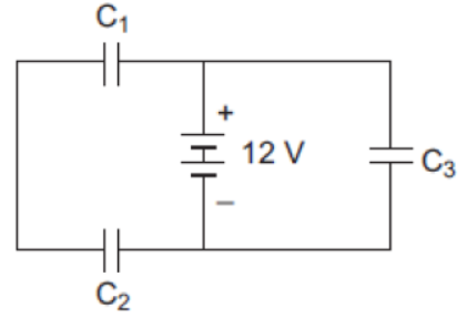
Find:
(i) charge on each capacitor
(ii) equivalent capacitance of the network
(iii) energy stored in the network of capacitors
Answer: From the circuit diagram, capacitors \( C_1 \) and \( C_2 \) are connected in series, and this combination is connected in parallel with the capacitor \( C_3 \) across the 12 V battery.
**(ii) Calculation of Equivalent Capacitance \( C_{eq} \):**
- First, the equivalent capacitance \( C_{12} \) of the series combination of \( C_1 = 6\,\mu\text{F} \) and \( C_2 = 6\,\mu\text{F} \) is:
\[ C_{12} = \frac{C_1 C_2}{C_1 + C_2} = \frac{6 \times 6}{6 + 6} = 3\,\mu\text{F} \]
- Now, \( C_{12} \) is connected in parallel with \( C_3 = 6\,\mu\text{F} \). The equivalent capacitance of the network is:
\[ C_{eq} = C_{12} + C_3 = 3\,\mu\text{F} + 6\,\mu\text{F} = 9\,\mu\text{F} \]
**(i) Calculation of Charge on Each Capacitor:**
- Since \( C_3 \) is in parallel with the battery, the potential difference across it is \( V = 12\text{ V} \). The charge \( Q_3 \) is:
\[ Q_3 = C_3 V = 6\,\mu\text{F} \times 12\text{ V} = 72\,\mu\text{C} \]
- The series combination of \( C_1 \) and \( C_2 \) is also in parallel across the 12 V battery, so the potential difference across the branch is \( 12\text{ V} \). The charge is the same on both capacitors:
\[ Q_1 = Q_2 = C_{12} V = 3\,\mu\text{F} \times 12\text{ V} = 36\,\mu\text{C} \]
**(iii) Calculation of Energy Stored in the Network:**
The total electrostatic energy \( U \) stored in the network is:
\[ U = \frac{1}{2} C_{eq} V^2 = \frac{1}{2} \times (9 \times 10^{-6}\text{ F}) \times (12\text{ V})^2 \]
\[ U = 4.5 \times 144 \times 10^{-6}\text{ J} = 6.48 \times 10^{-4}\text{ J} = 648\,\mu\text{J} \]
In simple words: (i) The charge on \( C_1 \) and \( C_2 \) is 36 microcoulombs each, and the charge on \( C_3 \) is 72 microcoulombs. (ii) The total combined capacitance is 9 microfarads. (iii) The total energy stored in the circuit is 648 microjoules.
Exam Tip: Be sure to treat parallel branches as having the same full battery voltage of 12 V. This simplifies the charge calculations on each branch.
Question 4. A 500 µC charge is at the centre of a square of side 10 cm. Find the work done in moving a charge of 10 µC between two diagonally opposite points on the square.
Answer: Let a charge \( Q = 500\,\mu\text{C} \) be at the center of the square. The two diagonally opposite corners of a square (let's call them A and B) are at an equal distance \( r \) from its center: \[ r = \frac{\sqrt{2} \times \text{side}}{2} = \frac{\text{side}}{\sqrt{2}} \]
The electric potential at point A due to the charge \( Q \) is:
\[ V_A = \frac{1}{4\pi\varepsilon_0} \frac{Q}{r} \]
The electric potential at point B due to the charge \( Q \) is:
\[ V_B = \frac{1}{4\pi\varepsilon_0} \frac{Q}{r} \]
Since \( V_A = V_B \), the potential difference \( \Delta V \) between these two diagonally opposite corners is zero:
\[ \Delta V = V_B - V_A = 0 \]
The work done \( W \) in moving a charge \( q = 10\,\mu\text{C} \) between these two points is:
\[ W = q \Delta V = (10 \times 10^{-6}\text{ C}) \times 0 = 0 \]
Therefore, the work done is **zero**.
In simple words: The center of the square is at the same distance from all corners. Because the opposite corners have the exact same voltage, no work is required to move a charge from one corner to the other.
Exam Tip: Clearly state that diagonally opposite points are equidistant from the center of the square, making their potentials equal and the potential difference zero.
Question 5. Calculate the work done to dissociate the system of three charges placed on the vertices of a triangle as shown. Here q =1.6x 10- 10 C.
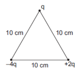
Answer: The three charges are placed at the vertices of an equilateral triangle of side \( d = 10\text{ cm} = 0.1\text{ m} \):
- \( q_1 = q = 1.6 \times 10^{-10}\text{ C} \)
- \( q_2 = -4q \)
- \( q_3 = +2q \)
The total electrostatic potential energy \( U \) of the system is the sum of the potential energies of all three pairs:
\[ U = \frac{1}{4\pi\varepsilon_0} \left[ \frac{q_1 q_2}{d} + \frac{q_2 q_3}{d} + \frac{q_3 q_1}{d} \right] \]
\[ U = \frac{1}{4\pi\varepsilon_0 d} [ q(-4q) + (-4q)(2q) + (2q)(q) ] \]
\[ U = \frac{1}{4\pi\varepsilon_0 d} [ -4q^2 - 8q^2 + 2q^2 ] \]
\[ U = \frac{1}{4\pi\varepsilon_0 d} [ -10q^2 ] \]
Substituting \( \frac{1}{4\pi\varepsilon_0} = 9 \times 10^9\text{ N}\cdot\text{m}^2/\text{C}^2 \) and \( q = 1.6 \times 10^{-10}\text{ C} \):
\[ U = \frac{9 \times 10^9}{0.1} \times \left[ -10 \times (1.6 \times 10^{-10}\text{ C})^2 \right] \]
\[ U = (9 \times 10^{10}) \times [ -10 \times 2.56 \times 10^{-20} ] \]
\[ U = (9 \times 10^{10}) \times [ -2.56 \times 10^{-19} ] = -2.304 \times 10^{-8}\text{ J} \]
The work done \( W \) required to completely dissociate the system of charges (i.e., to separate them to infinity where potential energy is zero) is:
\[ W = U_{\infty} - U = 0 - (-2.304 \times 10^{-8}\text{ J}) = 2.304 \times 10^{-8}\text{ J} \]
In simple words: The potential energy holding the charges together is \( -2.304 \times 10^{-8} \) joules. To tear them apart and send them to infinity, we must supply an equal and positive amount of work, which is \( 2.304 \times 10^{-8} \) joules.
Exam Tip: Be sure to clearly state that the work done to dissociate the system is \( W = -U \), where \( U \) is the initial potential energy of the system.
Question 6. Obtain the equivalent capacitance of the network given below. For a supply of 300 V, determine the charge and voltage across C4 .
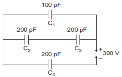
Answer: Let us analyze the capacitor network with the standard values:
- \( C_1 = 100\text{ pF} \), \( C_2 = 200\text{ pF} \), \( C_3 = 200\text{ pF} \), \( C_4 = 100\text{ pF} \)
- Total supply voltage, \( V = 300\text{ V} \)
**1. Calculation of Equivalent Capacitance (\( C_{eq} \)):**
- Capacitors \( C_2 \) and \( C_3 \) are connected in series. Let their equivalent capacitance be \( C_{23} \):
\[ \frac{1}{C_{23}} = \frac{1}{C_2} + \frac{1}{C_3} = \frac{1}{200} + \frac{1}{200} = \frac{2}{200} \implies C_{23} = 100\text{ pF} \]
- The series combination \( C_{23} \) is in parallel with \( C_1 \). Let their equivalent capacitance be \( C_{123} \):
\[ C_{123} = C_{23} + C_1 = 100\text{ pF} + 100\text{ pF} = 200\text{ pF} \]
- This combination \( C_{123} \) is connected in series with \( C_4 = 100\text{ pF} \). The total equivalent capacitance \( C_{eq} \) of the network is:
\[ \frac{1}{C_{eq}} = \frac{1}{C_{123}} + \frac{1}{C_4} = \frac{1}{200} + \frac{1}{100} = \frac{1 + 2}{200} = \frac{3}{200} \]
\[ \implies C_{eq} = \frac{200}{3}\text{ pF} \approx 66.7\text{ pF} \]
**2. Calculation of Charge and Voltage Across \( C_4 \):**
- Since \( C_4 \) is in series with the combination \( C_{123} \), the total charge \( Q_{total} \) drawn from the 300 V supply passes through \( C_4 \):
\[ Q_4 = C_{eq} \times V = \left(\frac{200}{3} \times 10^{-12}\text{ F}\right) \times 300\text{ V} = 2 \times 10^{-8}\text{ C} \quad (\text{or } 20000\text{ pC}) \]
- The potential difference \( V_4 \) across \( C_4 \) is:
\[ V_4 = \frac{Q_4}{C_4} = \frac{2 \times 10^{-8}\text{ C}}{100 \times 10^{-12}\text{ F}} = 200\text{ V} \]
In simple words: The equivalent capacitance of the network is \( \frac{200}{3} \) pF. The charge flowing through \( C_4 \) is \( 2 \times 10^{-8} \) coulombs, and the voltage drop across it is 200 volts.
Exam Tip: Draw the simplified equivalent circuits step-by-step to show how the series and parallel combinations reduce to a single equivalent capacitor.
Question 7. Two parallel plate capacitors X and Y, have the same area of plates and same separation between them. X has air between the plates while Y contains a dielectric medium of K = 4.
(i) Calculate capacitance of each capacitor if equivalent capacitance of the combination is 4 µF.
(ii) Calculate the potential difference between the plates of X and Y.
(iii) What is the ratio of electrostatic energy stored in X and Y?
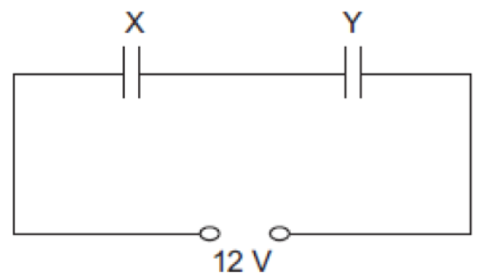
Answer: Let the capacitance of capacitor X (air-filled) be \( C_X = C \). Since Y has a dielectric constant \( K = 4 \) with the same dimensions, its capacitance is \( C_Y = 4C \). From the diagram, X and Y are connected in series across a \( 12\text{ V} \) battery.
**(i) Calculation of Capacitances:**
For a series combination, the equivalent capacitance \( C_{eq} \) is:
\[ \frac{1}{C_{eq}} = \frac{1}{C_X} + \frac{1}{C_Y} \implies \frac{1}{4\,\mu\text{F}} = \frac{1}{C} + \frac{1}{4C} = \frac{5}{4C} \]
\[ \frac{4C}{5} = 4\,\mu\text{F} \implies C = 5\,\mu\text{F} \]
Thus:
- Capacitance of X, \( C_X = \mathbf{5\,\mu\text{F}} \)
- Capacitance of Y, \( C_Y = 4C = \mathbf{20\,\mu\text{F}} \)
**(ii) Potential Difference Across Each:**
In a series combination, the charge \( Q \) on both capacitors is equal:
\[ Q = C_{eq} V = 4\,\mu\text{F} \times 12\text{ V} = 48\,\mu\text{C} \]
- Potential difference across X:
\[ V_X = \frac{Q}{C_X} = \frac{48\,\mu\text{C}}{5\,\mu\text{F}} = \mathbf{9.6\text{ V}} \]
- Potential difference across Y:
\[ V_Y = \frac{Q}{C_Y} = \frac{48\,\mu\text{C}}{20\,\mu\text{F}} = \mathbf{2.4\text{ V}} \]
**(iii) Ratio of Electrostatic Energy Stored:**
The energy stored in a capacitor can be written as \( U = \frac{Q^2}{2C} \). Since the charges are equal in series:
\[ \frac{U_X}{U_Y} = \frac{\left(\frac{Q^2}{2C_X}\right)}{\left(\frac{Q^2}{2C_Y}\right)} = \frac{C_Y}{C_X} = \frac{20\,\mu\text{F}}{5\,\mu\text{F}} = \frac{4}{1} \]
Thus, the ratio is **4 : 1**.
In simple words: (i) The capacitance of X is 5 microfarads and Y is 20 microfarads. (ii) The voltage across X is 9.6 volts and across Y is 2.4 volts. (iii) The ratio of energy stored in X and Y is 4 to 1 because X has lower capacitance and thus stores more energy for the same charge.
Exam Tip: Since the charge is identical in series, use the energy formula \( U = \frac{Q^2}{2C} \) directly to find the energy ratio, avoiding the use of voltages which can lead to calculation errors.
Question 8. A 800 pF capacitor is charged by a 100 V battery. After some time the battery is disconnected. The capacitor is then connected to another 800 pF capacitor. What is the electrostatic energy stored?
Answer: **Given parameters:**
Initial capacitance, \( C_1 = 800\text{ pF} = 800 \times 10^{-12}\text{ F} \)
Charging voltage, \( V_1 = 100\text{ V} \)
Uncharged capacitor, \( C_2 = 800\text{ pF} \), with \( V_2 = 0\text{ V} \)
1. The initial charge \( Q_1 \) stored in the first capacitor is:
\[ Q_1 = C_1 V_1 = (800 \times 10^{-12}\text{ F}) \times 100\text{ V} = 8 \times 10^{-8}\text{ C} \]
2. When this capacitor is disconnected from the battery and connected in parallel with the second uncharged capacitor, the total charge is redistributed, and they reach a common potential \( V' \):
\[ V' = \frac{C_1 V_1 + C_2 V_2}{C_1 + C_2} = \frac{(800 \times 10^{-12}\text{ F}) \times 100\text{ V} + 0}{(800 + 800) \times 10^{-12}\text{ F}} = 50\text{ V} \]
3. The total capacitance of the parallel combination is:
\[ C' = C_1 + C_2 = 1600\text{ pF} = 1600 \times 10^{-12}\text{ F} \]
4. The electrostatic energy \( U' \) stored in the combined system is:
\[ U' = \frac{1}{2} C' (V')^2 = \frac{1}{2} \times (1600 \times 10^{-12}\text{ F}) \times (50\text{ V})^2 \]
\[ U' = 800 \times 10^{-12} \times 2500 = 2 \times 10^{-6}\text{ J} \]
Therefore, the total electrostatic energy stored in the combination is **\( 2 \times 10^{-6}\text{ J} \)**.
In simple words: The first capacitor is charged to 100 volts and then connected to an identical uncharged capacitor. The voltage is cut in half to 50 volts, and the final stored energy of the combined system becomes \( 2 \times 10^{-6} \) joules (which is half of the original energy, with the other half being lost as heat during charge redistribution).
Exam Tip: Be sure to write the formula for common potential \( V' = \frac{C_1 V_1 + C_2 V_2}{C_1 + C_2} \) first to establish your calculation steps clearly.
Question 9. Calculate the electric potential at a point P, located at the centre of the square of point charges shown in the figure.
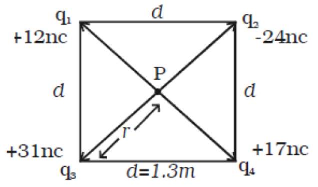
Answer: **Given parameters from the figure:**
Side of the square, \( d = 1.3\text{ m} \)
Charges at the corners:
- \( q_1 = +12\text{ nC} = +12 \times 10^{-9}\text{ C} \)
- \( q_2 = -24\text{ nC} = -24 \times 10^{-9}\text{ C} \)
- \( q_3 = +31\text{ nC} = +31 \times 10^{-9}\text{ C} \)
- \( q_4 = +17\text{ nC} = +17 \times 10^{-9}\text{ C} \)
The distance \( r \) of the center point P from any of the four corners is half the length of the diagonal of the square:
\[ r = \frac{\sqrt{2} d}{2} = \frac{d}{\sqrt{2}} = \frac{1.3}{\sqrt{2}}\text{ m} \approx 0.919\text{ m} \]
The net electric potential \( V_P \) at the center P is the algebraic sum of the potentials due to all four charges:
\[ V_P = \frac{1}{4\pi\varepsilon_0 r} (q_1 + q_2 + q_3 + q_4) \]
The sum of the charges is:
\[ q_{total} = (12 - 24 + 31 + 17) \times 10^{-9}\text{ C} = 36 \times 10^{-9}\text{ C} \]
Substituting the values:
\[ V_P = \frac{(9 \times 10^9\text{ N}\cdot\text{m}^2/\text{C}^2) \times (36 \times 10^{-9}\text{ C})}{\left(\frac{1.3}{\sqrt{2}}\text{ m}\right)} \]
\[ V_P = \frac{324 \times \sqrt{2}}{1.3}\text{ V} \approx \frac{324 \times 1.414}{1.3}\text{ V} \approx 352.4\text{ V} \]
Therefore, the electric potential at point P is **\( 352.4\text{ V} \)**.
In simple words: Since potential is a scalar, we simply sum up all the charges, which equals 36 nC. The distance from the center to each corner is \( \frac{1.3}{\sqrt{2}} \) meters. Dividing the total charge by this distance and multiplying by the electrostatic constant gives a potential of 352.4 volts.
Exam Tip: Be careful with the diagonal distance calculation: the diagonal is \( \sqrt{2}d \), so the distance to the center is \( \frac{d}{\sqrt{2}} \). Keep the calculations in fractional form until the final step to minimize rounding errors.
Question 10. Calculate the capacitance of the arrangement of two parallel plates of area A separated by a distance of d between them. K1 ,K2, and K3 are the dielectric constants of the three materials in between the plates as in the figure.
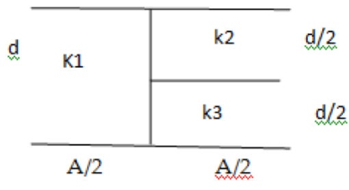
Answer: According to the plate arrangement shown in the figure, we can split the capacitor into two parallel sections: the left half and the right half, each having a plate area of \( A/2 \).
1. **Left Section (filled with dielectric \( K_1 \)):**
This forms a single capacitor \( C_1 \) with plate area \( A/2 \) and plate separation \( d \):
\[ C_1 = \frac{K_1 \varepsilon_0 (A/2)}{d} = \frac{K_1 \varepsilon_0 A}{2d} \]
2. **Right Section (filled with dielectrics \( K_2 \) and \( K_3 \)):**
This consists of two capacitors \( C_2 \) and \( C_3 \) connected in series, each having plate area \( A/2 \) and plate separation \( d/2 \):
\[ C_2 = \frac{K_2 \varepsilon_0 (A/2)}{d/2} = \frac{K_2 \varepsilon_0 A}{d} \]
\[ C_3 = \frac{K_3 \varepsilon_0 (A/2)}{d/2} = \frac{K_3 \varepsilon_0 A}{d} \]
The equivalent capacitance \( C_{23} \) of these two series-connected capacitors is:
\[ \frac{1}{C_{23}} = \frac{1}{C_2} + \frac{1}{C_3} = \frac{d}{\varepsilon_0 A} \left( \frac{1}{K_2} + \frac{1}{K_3} \right) = \frac{d}{\varepsilon_0 A} \left( \frac{K_2 + K_3}{K_2 K_3} \right) \]
\[ \implies C_{23} = \frac{\varepsilon_0 A}{d} \left( \frac{K_2 K_3}{K_2 + K_3} \right) \]
3. **Total Capacitance (\( C_{eq} \)):**
Since the left section (\( C_1 \)) and the right section (\( C_{23} \)) are in parallel, their capacitances add up:
\[ C_{eq} = C_1 + C_{23} = \frac{K_1 \varepsilon_0 A}{2d} + \frac{\varepsilon_0 A}{d} \left( \frac{K_2 K_3}{K_2 + K_3} \right) \]
\[ C_{eq} = \frac{\varepsilon_0 A}{d} \left[ \frac{K_1}{2} + \frac{K_2 K_3}{K_2 + K_3} \right] \]
In simple words: The capacitor is split into two halves. The left half is a single capacitor filled with \( K_1 \). The right half has two capacitors stacked on top of each other (in series) with \( K_2 \) and \( K_3 \). Combining the series half and adding it in parallel to the left half yields the final equivalent capacitance.
Exam Tip: Clearly show the physical division: horizontal divisions of distance \( d \) correspond to series capacitors, while vertical divisions of area \( A \) correspond to parallel capacitors.
Question 11. You are given an air filled parallel plate capacitor C1. The space between its plates is now filled with slabs of dielectric constants K1 and K2 as shown in C2 . Find the capacitances of the capacitor C2 if area of the plates is A and distance between the plates is d.
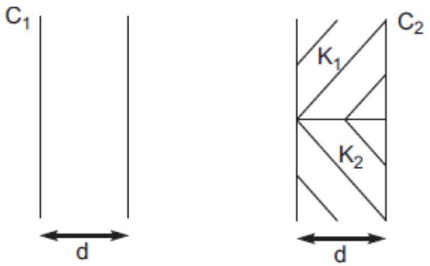
Answer: From the diagram for \( C_2 \), the space between the plates is divided horizontally into two equal halves of thickness \( d/2 \), each filled with dielectric slabs of constants \( K_1 \) and \( K_2 \) respectively, over the entire plate area \( A \).
This configuration represents two capacitors connected in series:
- \( C_a \) with dielectric \( K_1 \), plate area \( A \), and plate separation \( d/2 \):
\[ C_a = \frac{K_1 \varepsilon_0 A}{d/2} = \frac{2 K_1 \varepsilon_0 A}{d} \]
- \( C_b \) with dielectric \( K_2 \), plate area \( A \), and plate separation \( d/2 \):
\[ C_b = \frac{K_2 \varepsilon_0 A}{d/2} = \frac{2 K_2 \varepsilon_0 A}{d} \]
The equivalent capacitance \( C_2 \) of this series combination is:
\[ \frac{1}{C_2} = \frac{1}{C_a} + \frac{1}{C_b} = \frac{d}{2\varepsilon_0 A K_1} + \frac{d}{2\varepsilon_0 A K_2} \]
\[ \frac{1}{C_2} = \frac{d}{2\varepsilon_0 A} \left( \frac{1}{K_1} + \frac{1}{K_2} \right) = \frac{d}{2\varepsilon_0 A} \left( \frac{K_1 + K_2}{K_1 K_2} \right) \]
\[ C_2 = \frac{2\varepsilon_0 A}{d} \left( \frac{K_1 K_2}{K_1 + K_2} \right) \]
*(Note: We can also write this in terms of the initial capacitance \( C_1 = \frac{\varepsilon_0 A}{d} \) as \( C_2 = 2 C_1 \frac{K_1 K_2}{K_1 + K_2} \).)*
In simple words: The two dielectric slabs are stacked one on top of the other, each taking up half of the thickness \( d/2 \). This acts like two capacitors in series. Combining them mathematically gives a final capacitance of \( \frac{2\varepsilon_0 A}{d} \frac{K_1 K_2}{K_1 + K_2} \).
Exam Tip: Since the boundary between the dielectrics is parallel to the capacitor plates, the system must be treated as a series combination of two capacitors.
Question 12. Two identical parallel plate (air) capacitors C1 and C2 have capacitances C each. The between their plates is now filled with dielectrics as shown. If the two capacitors still have equalcapacitance, obtain the relation between dielectric constants K, K1 and K2 .
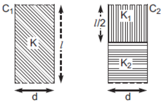
Answer: Let the area of each plate be \( A \) and the plate separation be \( d \). The original capacitance of each air-filled capacitor is \( C = \frac{\varepsilon_0 A}{d} \).
1. **For Capacitor \( C_1 \):**
The space between the plates is filled completely with a dielectric slab of constant \( K \). The new capacitance \( C_1' \) is:
\[ C_1' = K C = \frac{K \varepsilon_0 A}{d} \] [Equation 1]
2. **For Capacitor \( C_2 \):**
The space between the plates is divided vertically into two equal sections of area \( A/2 \) each, filled with dielectric slabs of constants \( K_1 \) and \( K_2 \) respectively, over the entire thickness \( d \). This acts as a parallel combination of two capacitors \( C_a \) and \( C_b \):
\[ C_a = \frac{K_1 \varepsilon_0 (A/2)}{d} = \frac{K_1 \varepsilon_0 A}{2d} \]
\[ C_b = \frac{K_2 \varepsilon_0 (A/2)}{d} = \frac{K_2 \varepsilon_0 A}{2d} \]
The total capacitance \( C_2' \) is:
\[ C_2' = C_a + C_b = \frac{\varepsilon_0 A}{2d} (K_1 + K_2) \] [Equation 2]
3. **Finding the Relationship:**
Since the two capacitors still have equal capacitance (\( C_1' = C_2' \)):
\[ \frac{K \varepsilon_0 A}{d} = \frac{\varepsilon_0 A}{2d} (K_1 + K_2) \]
Cancelling the common term \( \frac{\varepsilon_0 A}{d} \) on both sides:
\[ K = \frac{K_1 + K_2}{2} \]
This is the required relationship between the dielectric constants.
In simple words: The first capacitor is filled completely, so its capacitance becomes \( K \) times larger. The second capacitor is split side-by-side (in parallel) with \( K_1 \) and \( K_2 \). Equating their capacitances shows that \( K \) is the simple average of \( K_1 \) and \( K_2 \).
Exam Tip: Be sure to clearly state that a vertical division of area \( A/2 \) represents a parallel combination, whereas a horizontal division of distance represents a series combination.
Question 13. An electric dipole of length 1 cm, which placed with its axis making an angle of 60° with uniform electric field, experiences a torque of 6 √3 Nm. Calculate the potential energy of the dipole if it has charge ± 2 nC.
Answer: **Given parameters:**
Length of the dipole, \( 2a = 1\text{ cm} = 10^{-2}\text{ m} \)
Angle of orientation, \( \theta = 60^\circ \)
Torque experienced, \( \tau = 6\sqrt{3}\text{ N}\cdot\text{m} \)
Charge, \( q = 2\text{ nC} = 2 \times 10^{-9}\text{ C} \)
1. Calculate the electric dipole moment \( p \):
\[ p = q \times 2a = (2 \times 10^{-9}\text{ C}) \times 10^{-2}\text{ m} = 2 \times 10^{-11}\text{ C}\cdot\text{m} \]
2. The formula for the torque \( \tau \) acting on a dipole in a uniform electric field \( E \) is:
\[ \tau = p E \sin\theta \]
Substituting the given values:
\[ 6\sqrt{3} = p E \sin(60^\circ) \]
Since \( \sin(60^\circ) = \frac{\sqrt{3}}{2} \):
\[ 6\sqrt{3} = p E \left(\frac{\sqrt{3}}{2}\right) \implies p E = 12\text{ J} \]
3. The potential energy \( U \) of the electric dipole is given by:
\[ U = -p E \cos\theta \]
Substituting \( p E = 12\text{ J} \) and \( \theta = 60^\circ \):
\[ U = -12 \times \cos(60^\circ) = -12 \times 0.5 = -6\text{ J} \]
Therefore, the potential energy of the dipole is **\( -6\text{ J} \)**.
In simple words: First, we use the torque formula \( \tau = pE\sin\theta \) to find that the product \( pE \) is 12. Then, substituting this into the potential energy formula \( U = -pE\cos\theta \) gives a final potential energy of \( -6 \) joules.
Exam Tip: You don't need to calculate the electric field \( E \) explicitly. Finding the product \( p E \) as a single entity from the torque equation simplifies the math and prevents calculation mistakes.
Question 14. A capacitor of unknown capacitance is connected across a battery of V volts. The charge stored in it is 360 µC. When potential across the capacitor is reduced by 120 V, the charge stored in it becomes 120 µC.
Calculate:
(i) The potential V and the unknown capacitance C.
(ii) What will be the charge stored in the capacitor, if the voltage applied had increased by 120 V?
Answer: **(i) Calculation of potential \( V \) and capacitance \( C \):**
Initially, the charge stored is \( Q_1 = 360\,\mu\text{C} \) at voltage \( V \):
\[ Q_1 = C V \implies 360 \times 10^{-6} = C V \] [Equation 1]
When the potential is reduced by \( 120\text{ V} \), the new charge is \( Q_2 = 120\,\mu\text{C} \) at voltage \( (V - 120) \):
\[ Q_2 = C(V - 120) \implies 120 \times 10^{-6} = C (V - 120) \] [Equation 2]
Dividing Equation 1 by Equation 2:
\[ \frac{360 \times 10^{-6}}{120 \times 10^{-6}} = \frac{C V}{C(V - 120)} \implies 3 = \frac{V}{V - 120} \]
\[ 3(V - 120) = V \implies 3V - 360 = V \implies 2V = 360 \implies \mathbf{V = 180\text{ V}} \]
Substituting \( V = 180\text{ V} \) into Equation 1:
\[ 360 \times 10^{-6} = C \times 180 \implies C = \frac{360 \times 10^{-6}}{180} = \mathbf{2 \times 10^{-6}\text{ F} = 2\,\mu\text{F}} \]
**(ii) Charge if voltage is increased by 120 V:**
The new voltage is \( V' = V + 120 = 180\text{ V} + 120\text{ V} = 300\text{ V} \).
The charge \( Q' \) stored at this voltage is:
\[ Q' = C V' = 2 \times 10^{-6}\text{ F} \times 300\text{ V} = 600 \times 10^{-6}\text{ C} = \mathbf{600\,\mu\text{C}} \]
In simple words: (i) By dividing the two charging equations, we find that the original voltage \( V \) is 180 volts, which gives a capacitance of 2 microfarads. (ii) If we increase the voltage to 300 volts, the charge stored increases proportionally to 600 microcoulombs.
Exam Tip: Be sure to keep track of the units (microcoulombs to coulombs) during calculations to ensure your final capacitance is correctly written in microfarads.
Question 15. Figure shows two identical capacitors C1 and C2 each of 1.5 mF capacitance, connected to a battery of 2 V. Initially switch ‘S’ is closed. After sometimes ‘S’ is left open and dielectric slabs of dielectric constant K = 2 are inserted to fill completely the space between the plates of the two capacitors. How will the (i) charge and (ii) potential difference between the plates of the capacitors be affected after the slabs are inserted?
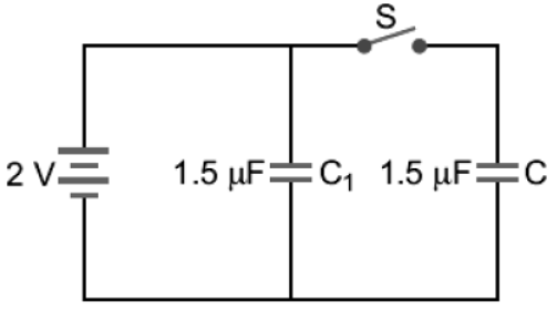
Answer: Initially, when switch S is closed, both capacitors \( C_1 = 1.5\,\mu\text{F} \) and \( C_2 = 1.5\,\mu\text{F} \) are connected in parallel across the \( 2\text{ V} \) battery. The charge on each capacitor is:
\[ Q_1 = Q_2 = C V = 1.5\,\mu\text{F} \times 2\text{ V} = 3.0\,\mu\text{C} \]
When the switch S is opened, capacitor \( C_1 \) remains connected to the battery, while capacitor \( C_2 \) is disconnected.
**1. For Capacitor \( C_1 \) (remains connected to the battery):**
- **(ii) Potential Difference:** The potential difference \( V_1' \) remains **constant** and equal to the battery voltage:
\[ V_1' = \mathbf{2\text{ V}} \]
- **(i) Charge:** Since the dielectric slab of \( K = 2 \) is inserted, the new capacitance is \( C_1' = K C_1 = 2 \times 1.5\,\mu\text{F} = 3.0\,\mu\text{F} \). The new charge is:
\[ Q_1' = C_1' V_1' = 3.0\,\mu\text{F} \times 2\text{ V} = \mathbf{6.0\,\mu\text{C}} \]
**2. For Capacitor \( C_2 \) (disconnected from the battery):**
- **(i) Charge:** Since it is isolated, the charge \( Q_2' \) remains **constant**:
\[ Q_2' = \mathbf{3.0\,\mu\text{C}} \]
- **(ii) Potential Difference:** The capacitance increases to \( C_2' = K C_2 = 3.0\,\mu\text{F} \). The new potential difference \( V_2' \) across its plates is:
\[ V_2' = \frac{Q_2'}{C_2'} = \frac{3.0\,\mu\text{C}}{3.0\,\mu\text{F}} = \mathbf{1\text{ V}} \]
In simple words: When the switch is opened, \( C_1 \) stays connected to the battery, so its voltage stays at 2 V while its charge doubles to 6 microcoulombs. \( C_2 \) is disconnected, so its charge is trapped at 3 microcoulombs, causing its voltage to drop from 2 V to 1 V when the dielectric is added.
Exam Tip: Clearly separate your analysis into two distinct cases: "battery connected" (where voltage remains constant) and "battery disconnected" (where charge remains constant) to avoid confusion.
Question 16. A network of four capacitors each of 15 µF capacitance is connected to a 500 V supply as shown in the figure. Determine (a) equivalent capacitance of the network and (b) charge on each capacitor.
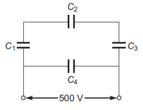
Answer: From the circuit diagram, capacitors \( C_1, C_2, \) and \( C_3 \) are connected in series with each other. This entire series combination is connected in parallel with the capacitor \( C_4 \) across the \( 500\text{ V} \) supply.
**(a) Calculation of Equivalent Capacitance \( C_{eq} \):**
- First, find the equivalent capacitance \( C_{123} \) of the series combination of \( C_1 = 15\,\mu\text{F} \), \( C_2 = 15\,\mu\text{F} \), and \( C_3 = 15\,\mu\text{F} \):
\[ \frac{1}{C_{123}} = \frac{1}{C_1} + \frac{1}{C_2} + \frac{1}{C_3} = \frac{1}{15} + \frac{1}{15} + \frac{1}{15} = \frac{3}{15} = \frac{1}{5} \]
\[ \implies C_{123} = 5\,\mu\text{F} \]
- Since \( C_{123} \) is in parallel with \( C_4 = 15\,\mu\text{F} \), the total equivalent capacitance is:
\[ C_{eq} = C_{123} + C_4 = 5\,\mu\text{F} + 15\,\mu\text{F} = \mathbf{20\,\mu\text{F}} \]
**(b) Calculation of Charge on Each Capacitor:**
- Since the parallel combination is connected across the \( 500\text{ V} \) supply, the voltage across \( C_4 \) is \( V = 500\text{ V} \). The charge \( Q_4 \) is:
\[ Q_4 = C_4 V = 15\,\mu\text{F} \times 500\text{ V} = 7500\,\mu\text{C} = \mathbf{7.5 \times 10^{-3}\text{ C}} \]
- The series combination of \( C_1, C_2, C_3 \) is also connected across the \( 500\text{ V} \) supply. Since they are in series, they carry the same charge \( Q_1 = Q_2 = Q_3 \):
\[ Q_1 = Q_2 = Q_3 = C_{123} V = 5\,\mu\text{F} \times 500\text{ V} = 2500\,\mu\text{C} = \mathbf{2.5 \times 10^{-3}\text{ C}} \]
In simple words: (a) The equivalent capacitance of the three series capacitors is 5 microfarads, which when added to the parallel 15 microfarad capacitor gives a total capacitance of 20 microfarads. (b) The charge on the single parallel capacitor is \( 7.5 \times 10^{-3} \) coulombs, and the charge on each of the three series capacitors is \( 2.5 \times 10^{-3} \) coulombs.
Exam Tip: Be sure to write the charge values clearly for each of the four capacitors individually. It is common to forget to explicitly state the charges for the series components.
Free study material for Physics
Electric Potential And Capacitance Printable Worksheets and Exercises for Class 12 Physics
Practice Exercises for Class 12 Physics Electric Potential And Capacitance
Review targeted practice exercises for Class 12 Physics Electric Potential And Capacitance. Curated to match official CBSE guidelines, these printable problem sets support daily revision and improve overall test readiness.
Step-by-Step Solutions and Practice Guidelines
Built using official NCERT guidelines for Class 12 Physics, these practice sheets provide reliable academic support. Cross-reference your completed work with our detailed solutions to learn standard answer-writing formats for CBSE exams.
Enhance Speed with Online Practice
Consistent engagement with these exercises builds familiarity with recurring exam themes. If specific areas within Electric Potential And Capacitance cause trouble, utilize our dedicated NCERT solutions for Class 12 Physics to clear up doubts immediately.
FAQs
You can download the latest chapter-wise printable worksheets for Class 12 Physics Electric Potential And Capacitance for free from StudiesToday.com. These have been made as per the latest CBSE curriculum for this academic year.
Yes, Class 12 Physics worksheets for Electric Potential And Capacitance focus on activity-based learning and also competency-style questions. This helps students to apply theoretical knowledge to practical scenarios.
Yes, we have provided solved worksheets for Class 12 Physics Electric Potential And Capacitance to help students verify their answers instantly.
Yes, our Class 12 Physics test sheets are mobile-friendly PDFs and can be printed by teachers for classroom.
For Electric Potential And Capacitance, regular practice with our worksheets will improve question-handling speed and help students understand all technical terms and diagrams.