

Official Class 12 Physics Worksheets: 3 Mark Question Bank
Explore structured practice materials through the CBSE Class 12 Physics 3 Mark Question Bank Worksheet. Tailored for Class 12 learners, utilizing these Physics worksheets ensures thorough preparation and strengthens problem-solving accuracy before final school evaluations.
Solved Practice Worksheets for Physics
Navigate directly to the solved Physics worksheets using the digital viewer below. Each practice set includes detailed step-by-step solutions, allowing students to instantly cross-check their work and identify areas requiring further revision.
CBSE Class 12 Physics 3 mark Question Bank. Students can download these worksheets and practice them. This will help them to get better marks in examinations. Also refer to other worksheets for the same chapter and other subjects too. Use them for better understanding of the subjects.
Please click the link below to download full pdf file for CBSE Class 12 Physics 3 mark Question Bank.
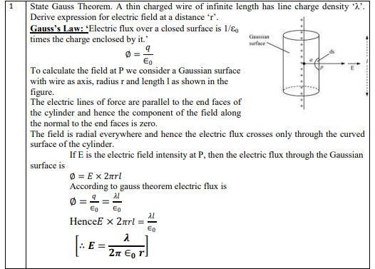
Question 1. State Gauss Theorem. A thin charged wire of infinite length has line charge density ‘λ’. Derive expression for electric field at a distance ‘r’.
Answer: Gauss's Law states that the total electric flux traversing any enclosed surface is equal to \( \frac{1}{\epsilon_0} \) times the net charge enclosed by that surface: \[ \Phi = \frac{q_{\text{enclosed}}}{\epsilon_0} \] **Derivation:** To find the electric field of an infinitely long, straight wire carrying a uniform linear charge density \( \lambda \), we construct a cylindrical Gaussian surface of radius \( r \) and length \( l \) coaxial with the wire. The electric field \( \vec{E} \) is directed radially outwards, meaning it is perpendicular to the wire. Since the normal vectors of the circular flat end caps of the cylinder are parallel to the wire, they are perpendicular to \( \vec{E} \), so no flux passes through the end caps: \[ \int_{\text{ends}} \vec{E} \cdot d\vec{A} = 0 \] The electric field is perpendicular to the curved surface of the cylinder, and its magnitude \( E \) is constant everywhere on this curved surface. Thus, the total flux \( \Phi \) is: \[ \Phi = \int_{\text{curved}} E \, dA = E (2\pi r l) \] By Gauss's Law, the charge enclosed by the cylindrical Gaussian surface is \( q_{\text{enclosed}} = \lambda l \). Therefore: \[ E (2\pi r l) = \frac{\lambda l}{\epsilon_0} \]
\( \implies E = \frac{\lambda}{2\pi \epsilon_0 r} \)
In simple words: Gauss's theorem tells us how the electric field flows out of a closed boundary. For a charged wire, wrapping it in an imaginary cylinder shows that the electric field gets weaker in direct proportion to how far you are from the wire.
Exam Tip: Always remember to mention that the electric flux through the flat end caps of the cylindrical Gaussian surface is zero because the electric field vector is perpendicular to the area vector of those caps.
Question 2. A parallel plate capacitor is charged by a battery to a potential V. It is disconnected and a dielectric slab is inserted to completely fill the space between the plates. How will (a) its capacitance (b) electric field between the plates and (c) energy stored in the capacitor be affected? Justify your answer in each case.
Answer: Since the capacitor is disconnected from the charging battery, the total charge \( Q \) on its plates remains constant. Let the initial parameters of the vacuum capacitor be capacitance \( C_0 \text{,} \) electric field \( E_0 \text{,} \) and stored energy \( U_0 \text{.} \) A dielectric slab with a dielectric constant \( k \) is now introduced to fill the entire gap between the plates.
(a) **Capacitance:** The capacitance increases. The presence of the dielectric material reduces the potential difference, causing the capacitance to increase by a factor of \( k \): \[ C_d = k C_0 \]
(b) **Electric Field:** The electric field between the plates decreases. The polarization of the dielectric creates an opposing electric field, reducing the net electric field by a factor of \( k \): \[ E_d = \frac{E_0}{k} \]
(c) **Energy Stored:** The energy stored in the capacitor decreases. Since the charge \( Q \) remains constant, we use the energy formula \( U = \frac{Q^2}{2C} \). As capacitance \( C \) increases to \( k C_0 \text{,} \) the stored energy is reduced by a factor of \( k \): \[ U_d = \frac{Q^2}{2 C_d} = \frac{Q^2}{2 k C_0} = \frac{U_0}{k} \]
In simple words: Once you disconnect the battery, the charge on the plates cannot escape. Sliding in a dielectric makes it easier for the plates to hold that charge (higher capacitance), which lowers both the electric field and the stored energy.
Exam Tip: Always specify whether the battery remains connected or is disconnected, as this determines whether voltage \( V \) or charge \( Q \) stays constant during the dielectric insertion.
Question 3. Electric charge is uniformly distributed on the surface of a spherical balloon. Show how electric intensity and electric potential vary (a) on the surface (b) inside and (c) outside.
Answer: Let \( R \) be the radius of the spherical balloon carrying a total charge \( q \) uniformly distributed on its surface.
(a) **On the Surface (\( r = R \)):** - The electric intensity is maximum and is given by: \[ E = \frac{\sigma}{\epsilon_0} = \frac{q}{4\pi\epsilon_0 R^2} \] - The electric potential is: \[ V = \frac{q}{4\pi\epsilon_0 R} \]
(b) **Inside the Balloon (\( r < R \)):** - The electric intensity is zero everywhere inside (\( E = 0 \)) because there is no enclosed charge within any internal Gaussian surface. - The electric potential remains constant and is equal to its value on the surface: \[ V = \frac{q}{4\pi\epsilon_0 R} \]
(c) **Outside the Balloon (\( r > R \)):** - The balloon behaves as if its entire charge were concentrated at the center. The electric intensity decreases as the inverse square of the distance: \[ E = \frac{q}{4\pi\epsilon_0 r^2} \propto \frac{1}{r^2} \] - The electric potential decreases inversely with distance: \[ V = \frac{q}{4\pi\epsilon_0 r} \propto \frac{1}{r} \]
In simple words: Inside a hollow charged shell, there is no electric force at all, but the potential is flat and equal to the surface potential. Outside, the shell behaves just like a tiny point charge located at its center.
Exam Tip: Ensure you draw both graphs side by side - showing \( E \) dropping abruptly to zero inside, and \( V \) remaining flat inside - as they are highly valued by examiners.
Question 4. (a) Why do we prefer potentiometer to measure the emf of cell than a voltmeter? (b) With suitable circuit diagram, show how emfs of a cell can be compared using a potentiometer?
Answer: (a) A potentiometer is highly preferred over a voltmeter for measuring the emf of a cell because it operates on the null-point method. Under balanced conditions, it draws absolutely zero current from the cell under measurement. Consequently, it measures the true open-circuit electromotive force (emf) of the cell. In contrast, a voltmeter must draw some current to show a deflection, thereby measuring the terminal potential difference rather than the true emf.
(b) **Comparison of EMFs:** To compare the emfs of two cells, \( E_1 \) and \( E_2 \text{,} \) we connect them in the secondary circuit of a potentiometer through a two-way key. 1. First, we close the gap connecting cell \( E_1 \) into the circuit while keeping the other cell out. The jockey is moved along the potentiometer wire AB to find the balance point \( J_1 \) at length \( l_1 \text{.} \) The potential drop across \( l_1 \) is equal to \( E_1 \): \[ E_1 = k l_1 \] ... (1) 2. Next, we disconnect cell \( E_1 \) and connect cell \( E_2 \text{.} \) We find the new balance point \( J_2 \) at a length \( l_2 \text{.} \) The potential drop across \( l_2 \) balances \( E_2 \): \[ E_2 = k l_2 \] ... (2) 3. Dividing equation (1) by (2) yields the ratio of their emfs: \[ \frac{E_1}{E_2} = \frac{l_1}{l_2} \]
In simple words: (a) A voltmeter acts like a small leak in a water tank, slightly changing the pressure it tries to measure. A potentiometer measures the pressure without letting any water leak out, giving the true EMF. (b) By balancing two different cells on the wire and comparing where they balance, we easily find the ratio of their voltages.
Exam Tip: Always draw the primary circuit with a driver cell and a rheostat, and keep the polarities of the driver cell and the experimental cells same at the main terminal point A.
Question 5. Draw Circuit diagram for a meter bridge to determine the unknown resistance of a resistor. Obtain the balance condition for a meter bridge. Find the shift in the balance point for a meter bridge when two resistors in its two gaps, are interchanged.
Answer: Let \( S \) represent the unknown resistor whose value needs to be determined, which is connected in one of the gaps (say, the right gap). In the other gap (the left gap), a known resistance box \( R \) is connected. The bridge setup is adjusted by moving the sliding jockey along the uniform bridge wire AC of length 100 cm until the galvanometer shows no deflection (null point), establishing the balanced state. For a balanced Wheatstone bridge, the ratio of the resistances is given by: \[ \frac{P}{Q} = \frac{R}{S} \] ... (1) Let \( l \) be the balancing length measured from the end A (segment AD). The remaining length of the wire is \( 100 - l \) (segment DC). If \( r \) is the resistance per unit length of the bridge wire, then: - Resistance of segment AD, \( P = r \cdot l \) - Resistance of segment DC, \( Q = r \cdot (100 - l) \) Substituting these expressions into the balance condition (1): \[ \frac{r \cdot l}{r \cdot (100 - l)} = \frac{R}{S} \]
\( \implies \frac{R}{S} = \frac{l}{100 - l} \) From this, the unknown resistance is calculated as: \[ S = R \cdot \left( \frac{100 - l}{l} \right) \] **Interchanging the Resistors:** If the resistors \( R \) and \( S \) are swapped between the gaps, the ratio of resistances is inverted. Thus, the balancing length \( l' \) measured from end A is interchanged with the other segment, becoming: \[ l' = 100 - l \] The shift in the balance point is: \[ \Delta l = |l' - l| = |100 - 2l| \]
In simple words: A meter bridge is a physical layout of a Wheatstone bridge. Swapping the positions of the known and unknown resistors simply flips the balancing lengths, shifting the balance point from \( l \) to \( 100 - l \).
Exam Tip: Always specify that the wire has uniform cross-section and composition, as this ensures that resistance per unit length \( r \) remains constant throughout the wire.
Question 6. With the help of a circuit diagram, explain how a potentiometer can be used to measure the internal resistance of a primary cell.
Answer: To measure the internal resistance of a primary cell \( E \text{,} \) we connect it to a potentiometer. 1. **Step 1:** Keep the primary circuit key \( K_1 \) closed and the shunt-circuit key \( K_2 \) open (no current is drawn through the external resistance box \( R \)). Slide the jockey along wire AB to find the balancing point \( J \) at length \( l_1 \text{.} \) This balances the cell's open-circuit emf \( E \): \[ E = \phi l_1 \] ... (1) where \( \phi \) is the potential gradient. 2. **Step 2:** Close key \( K_2 \text{,} \) connecting a known resistance \( R \) in parallel with the cell. Slide the jockey to locate the new balancing point \( J' \) at length \( l_2 \text{.} \) This balances the terminal potential difference \( V \) of the cell: \[ V = \phi l_2 \] ... (2) 3. **Step 3:** Dividing equation (1) by (2): \[ \frac{E}{V} = \frac{l_1}{l_2} \] The internal resistance \( r \) is related to the external resistance \( R \text{,} \) emf \( E \text{,} \) and terminal voltage \( V \) by: \[ V = E - I r \implies r = \left( \frac{E - V}{I} \right) = \left( \frac{E - V}{V} \right) R \]
\( \implies r = \left( \frac{E}{V} - 1 \right) R \) Substituting \( \frac{E}{V} = \frac{l_1}{l_2} \): \[ r = \left( \frac{l_1}{l_2} - 1 \right) R \]
In simple words: First, we find the balance point without drawing current from the cell to measure its EMF. Then, we connect a known resistor in parallel, drawing current and measuring the lower terminal voltage. The drop in balance point tells us how much the internal resistance held back.
Exam Tip: Always remember to calculate the final internal resistance \( r \) using the formula \( r = \left( \frac{l_1}{l_2} - 1 \right) R \) and verify that the units of the result are in Ohms (\( \Omega \)).
Question 7. How will you convert a galvanometer into an ammeter of range 0 - I amperes? What is the effective resistance of an ammeter?
Answer: To convert a sensitive galvanometer into an ammeter capable of measuring large currents in the range \( 0 - I \text{,} \) a small resistance called a shunt (\( S \)) is connected in parallel with the galvanometer coil. Let \( R_G \) be the resistance of the galvanometer coil, and \( I_g \) be the maximum current required to produce a full-scale deflection in the galvanometer. To measure a maximum line current \( I \text{,} \) the current through the galvanometer must not exceed \( I_g \text{,} \) meaning the remaining current \( I - I_g \) must pass through the shunt resistor \( S \text{.} \) Since the galvanometer and the shunt resistor are connected in parallel, the potential difference across them is identical: \[ I_g R_G = (I - I_g) S \] From this, the required shunt resistance is calculated as: \[ S = \frac{I_g R_G}{I - I_g} \] The effective resistance \( R_A \) of the resulting ammeter (which is the parallel combination of \( R_G \) and \( S \)) is: \[ R_A = \frac{R_G \cdot S}{R_G + S} \]
In simple words: To protect a delicate galvanometer from large currents, we place a low-resistance detour (a shunt) parallel to it. This diverts most of the current away from the galvanometer, and the combined system acts as a low-resistance ammeter.
Exam Tip: Always remember that an ideal ammeter has zero resistance and is connected in series in a circuit, while in practice we connect a very small shunt in parallel to achieve this.
Question 8. How will you select materials for making permanent magnets, electromagnets and cores of transformers?
Answer: The criteria for selecting magnetic materials depend on their intended application:
**A. Permanent Magnets:** To ensure the magnet retains its magnetic strength over a long period under varying external conditions, the chosen material must possess: 1. **High Retentivity:** So it remains highly magnetized even when the external magnetizing field is removed. 2. **High Coercivity:** To resist demagnetization from stray magnetic fields or temperature fluctuations. 3. **High Permeability:** To easily achieve strong magnetization. *Examples:* Alnico, Steel.
**B. Electromagnets:** Electromagnets need to be magnetized rapidly when current is switched on, and lose magnetization completely when current is cut off. The materials should have: 1. **High Initial Permeability:** To produce strong magnetic fields quickly. 2. **Low Retentivity:** So it ceases to be magnetic as soon as the current is switched off. *Example:* Soft iron.
**C. Transformer Cores:** Since transformer cores undergo continuous, rapid cycles of magnetization and demagnetization, the material must minimize energy losses: 1. **High Initial Permeability:** To maximize flux linkage. 2. **Low Hysteresis Loss:** To prevent energy dissipation as heat during magnetic cycles. 3. **Low Resistivity (or Laminated Design with high resistivity):** Laminated sheets are used to restrict the flow of eddy currents and limit heating losses. *Example:* Soft iron or silicon steel.
In simple words: Permanent magnets need tough materials that keep their magnetism (high retentivity and coercivity), electromagnets need materials that turn on and off easily (low retentivity), and transformer cores need materials that don't waste energy as heat when switching polarities rapidly.
Exam Tip: Always remember to name 'soft iron' as the ideal material for electromagnets and transformer cores due to its high magnetic permeability and low retentivity.
Question 9. What are eddy currents? Write there important applications. Why are eddy current produced in the cores of transformers and a.c. generators disadvantageous. How can they be minimised?
Answer: **Eddy Currents (Foucault Currents):** When a solid, bulk piece of conductor is exposed to a changing magnetic field, induced circular currents are generated within the body of the material. Because these currents circulate in closed loops resembling the swirling whirlpools or eddies in water, they are called eddy currents. Their direction opposes the change in magnetic flux, in accordance with Lenz’s Law.
**Key Applications:** - **Magnetic Braking in Trains:** Powerful electromagnets above the rails induce eddy currents in the rails, creating an opposing force that smoothly halts the train. - **Electromagnetic Damping:** Used in deadbeat galvanometers to bring the coil to rest quickly. - **Induction Furnace:** High-frequency eddy currents generate intense heat to melt metals. - **Speedometers and Power Meters:** Utilize eddy current drag to rotate indicator needles or dials.
**Disadvantages:** In devices like transformers and AC generators, eddy currents circulate in the iron cores, dissipating valuable electrical energy as unwanted heat (proportional to \( I^2 R \)). This reduces efficiency and can damage the insulation of the windings.
**Minimization:** Eddy currents are minimized by constructing the core from thin, insulated metal sheets (laminations) stacked together rather than a single solid block. The planes of these laminations are aligned parallel to the magnetic field, effectively cutting off the wide loop paths of the eddy currents and greatly reducing their strength.
In simple words: Eddy currents are like little electrical whirlpools created inside a block of metal when a magnetic field changes. In transformers, they waste power by heating up the core, which we prevent by slicing the core into thin, insulated layers.
Exam Tip: Lamination of cores does not completely eliminate eddy currents; it merely breaks down their paths into much smaller loops, thereby reducing energy loss to a minimum.
Question 10. Derive expression for the magnetic energy required to build up the current I in a coil of self-inductance L is given by ½ LI2 . Hence derive expression for the magnetic energy density.
Answer: When the electric current in a coil of self-inductance \( L \) increases, a back electromotive force (emf) \( e \) is induced, which opposes the growth of the current. To establish the current, an external power source must perform work against this opposing back emf. The magnitude of the back emf is given by: \[ e = L \frac{dI}{dt} \] The rate of work done (power \( P \)) at any instant when the current is \( I \) is: \[ P = \frac{dW}{dt} = e I = \left( L \frac{dI}{dt} \right) I = L I \frac{dI}{dt} \] The small amount of work done \( dW \) in a time interval \( dt \) is: \[ dW = L I \, dI \] The total work \( W \) required to increase the current from zero to its final steady value \( I \) is: \[ W = \int_0^I L I \, dI = L \left[ \frac{I^2}{2} \right]_0^I = \frac{1}{2} L I^2 \] This work is stored in the magnetic field of the coil as its **magnetic potential energy**.
**Magnetic Energy Density (\( u \)):** Energy density \( u \) is defined as the magnetic energy stored per unit volume of the space inside the inductor. Consider a long solenoid of cross-sectional area \( A \text{,} \) length \( l \text{,} \) and number of turns per unit length \( n \text{.} \) The self-inductance is \( L = \mu_0 n^2 A l \text{,} \) and the magnetic field inside is \( B = \mu_0 n I \implies I = \frac{B}{\mu_0 n} \). The total stored energy is: \[ U = \frac{1}{2} L I^2 = \frac{1}{2} (\mu_0 n^2 A l) \left( \frac{B}{\mu_0 n} \right)^2 = \frac{B^2}{2 \mu_0} A l \] The volume of the solenoid is \( V = A l \text{.} \) Therefore, the magnetic energy density \( u \) is: \[ u = \frac{U}{\text{Volume}} = \frac{U}{A l} = \frac{B^2}{2 \mu_0} \]
In simple words: Building up current in an inductor is like pulling a heavy spring; the work done to fight the resistance is stored in the magnetic field. The energy per unit of space is given by \( B^2 / 2\mu_0 \).
Exam Tip: During derivations, clearly state that you are ignoring resistive losses to focus purely on the inductive effects of the coil.
Question 11. State the underlying principle of transformer. How is the large scale transmission of electric energy over long distance done with the use of transformers?
Answer: **Underlying Principle:** A transformer operates on the principle of **mutual induction**. When an alternating current flows through the primary coil, it creates a continuously changing magnetic flux, which is linked to the secondary coil, thereby inducing an alternating electromotive force in the secondary coil.
**Long-Distance Power Transmission:** Electricity is transmitted over vast distances using a combination of step-up and step-down transformers to minimize power losses: 1. **Step-up at Power Stations:** The electricity generated at the power plant at a moderate voltage is stepped up to a very high voltage (and consequently low current) using a step-up transformer. 2. **Why High Voltage?** The power loss in transmission lines is given by \( P_{\text{loss}} = I^2 R \text{.} \) By transmitting at high voltage, the current \( I \) is significantly reduced, which dramatically lowers the energy lost as heat in the transmission lines. 3. **Step-down at Substations:** When the electricity reaches cities and distribution points, step-down transformers are used to safely reduce the high voltage back to lower, usable levels (like 220 V) for consumers.
In simple words: A transformer works because a changing magnetic field in one coil automatically creates a current in another coil nearby. We step up the voltage for travel to keep the current low, preventing the wires from wasting power as heat.
Exam Tip: Always write the formula \( P = I^2 R \) to show why lowering the current \( I \) drastically reduces the transmission power loss.
Question 12. How is the mutual inductance of a pair of coils affected when (1) Separation between the coils is increased. (2) The number of turns of each coil is increased. (3) A thin iron sheet is placed between two coils, other factors remaining the same. Explain answer in each case.
Answer: The mutual inductance \( M \) of two coils is affected as follows:
(1) **When separation is increased:** The mutual inductance **decreases**. This is because increasing the distance between the coils reduces the amount of magnetic flux from the primary coil that successfully links with the secondary coil.
(2) **When the number of turns is increased:** The mutual inductance **increases**. The formula for mutual inductance is: \[ M = \frac{\mu_0 \mu_r N_1 N_2 A}{l} \] Since \( M \) is directly proportional to the product of the number of turns (\( M \propto N_1 N_2 \)), increasing the turns of either coil increases the mutual inductance.
(3) **When a thin iron sheet is inserted:** The mutual inductance **increases**. Iron has a high relative magnetic permeability (\( \mu_r \)). Placing it between the coils concentrates and guides the magnetic flux lines, significantly improving the magnetic coupling between them.
In simple words: (1) Pulling the coils apart weakens their connection, lowering mutual inductance. (2) Adding more loops increases the magnetic field strength, boosting it. (3) Slipping iron between them acts like a superhighway for magnetic lines, making the connection much stronger.
Exam Tip: Be sure to state the equation \( M \propto \mu_r N_1 N_2 \) to justify your answers with mathematical backing.
Question 13. By stating sign conventions and assumptions used derive the relation between u,v and f in case of a concave mirror?
Answer: **Assumptions:** 1. The aperture of the spherical mirror is very small. 2. The object is a point object placed on the principal axis. 3. The incident rays make very small angles with the principal axis.
**Sign Conventions:** 1. All distances are measured from the pole (\( P \)) of the mirror. 2. Distances measured in the direction of the incident light are positive, while those in the opposite direction are negative. 3. Heights measured vertically upwards are positive; those downwards are negative.
**Derivation:** Consider an object AB of height \( h \) placed beyond the center of curvature \( C \) of a concave mirror. Its real, inverted image A'B' is formed between \( C \) and the focus \( F \text{.} \) The triangles \( \Delta A'B'F \) and \( \Delta MDF \) are similar (since \( \angle D = \angle B' = 90^\circ \text{,} \) \( \angle A'FB' = \angle MFD \) as vertically opposite angles). Therefore: \[ \frac{A'B'}{MD} = \frac{B'F}{FD} \] Since the aperture is small, \( D \) lies very close to \( P \text{,} \) so \( FD \approx FP = f \text{.} \) Also, \( MD = AB \text{.} \) \[ \frac{A'B'}{AB} = \frac{B'F}{FP} \] ... (1) Similarly, the triangles \( \Delta APB \) and \( \Delta A'PB' \) are similar. Therefore: \[ \frac{A'B'}{AB} = \frac{B'P}{BP} \] ... (2) Equating (1) and (2): \[ \frac{B'F}{FP} = \frac{B'P}{BP} \] Using sign conventions: - Object distance, \( BP = -u \) - Image distance, \( B'P = -v \) - Focal length, \( FP = -f \) - \( B'F = B'P - FP = -v - (-f) = -v + f \) Substituting these into the equation: \[ \frac{-v + f}{-f} = \frac{-v}{-u} \] \[ \frac{-v + f}{-f} = \frac{v}{u} \implies (-v + f)u = -f v \] \[ -uv + uf = -vf \] Dividing both sides by \( uvf \): \[ -\frac{1}{f} + \frac{1}{v} = -\frac{1}{u} \implies \frac{1}{f} = \frac{1}{v} + \frac{1}{u} \]
In simple words: By looking at similar triangles formed by light bouncing off a concave mirror and applying sign conventions (where distances opposite to the light are negative), we find that \( 1/f = 1/v + 1/u \).
Exam Tip: Always draw a neat, labeled ray diagram with arrows showing the direction of the incident and reflected rays to score full marks.
Question 14. Define total internal reflection of light? Hence write two advantages of total reflecting prisms over a plane mirror?
Answer: **Total Internal Reflection (TIR):** When a ray of light traveling through an optically denser medium strikes the interface of an optically rarer medium at an angle of incidence greater than the critical angle for that pair of media, the ray is completely reflected back into the denser medium. This phenomenon is known as total internal reflection.
**Two Advantages of Total Reflecting Prisms over Plane Mirrors:** 1. **No Silvering Required:** A total reflecting prism does not require chemical silvering on its surfaces to reflect light, eliminating the risk of degradation or peeling over time. 2. **No Multiple Ghost Images:** In a typical silvered glass plane mirror, multiple weak reflections occur from the front glass surface and silvered back, producing faint ghost images around the main image. A reflecting prism produces only a single, extremely sharp and bright image.
In simple words: Total internal reflection happens when light tries to exit glass at a very flat angle but gets completely bounced back inside like a perfect mirror. Prisms are better than regular mirrors because they don't require silver backing and never produce fuzzy double-images.
Exam Tip: Always remember to state both necessary conditions for TIR: 1) Light must travel from a denser to a rarer medium, and 2) The angle of incidence must be greater than the critical angle.
Question 15. A convex lens made up of refractive index n1 is kept in a medium of refractive index n2. Parallel rays of light are incident on the lens. Complete the path of rays of light emerging from the convex lens if (1) n1 > n2 (2) n1 = n2 (3) n1 < n2
Answer: The optical behavior of a lens immersed in an external medium is governed by the Lens Maker's Formula: \[ \frac{1}{f} = \left( \frac{n_1}{n_2} - 1 \right) \left( \frac{1}{R_1} - \frac{1}{R_2} \right) \]
(1) **When \( n_1 > n_2 \):** Since the refractive index of the lens is greater than the medium, \( \left( \frac{n_1}{n_2} - 1 \right) > 0 \text{.} \) The focal length remains positive. The lens behaves normally as a **converging lens**, bending parallel incident rays to focus them at a single point \( F \text{.} \)
(2) **When \( n_1 = n_2 \):** Since the refractive indices are equal, \( \left( \frac{n_1}{n_2} - 1 \right) = 0 \text{,} \) meaning the focal length \( f \) becomes infinite (\( f \to \infty \)). No refraction occurs at the boundaries, and the lens behaves like a **simple transparent glass plate**, allowing light rays to pass straight through without bending.
(3) **When \( n_1 < n_2 \):** Since the lens is less optically dense than the medium, \( \left( \frac{n_1}{n_2} - 1 \right) < 0 \text{.} \) This reverses the sign of the focal length, making it negative. The lens changes its nature and behaves as a **diverging lens**, causing parallel incident rays to spread apart as if they were originating from a virtual focus.
In simple words: A lens only bends light because of the speed difference between glass and air. (1) If the lens is denser than the medium, it converges light. (2) If they have identical densities, light slips straight through. (3) If the lens is less dense than the medium, it flips its behavior to diverge light.
Exam Tip: Always remember that when a lens is placed in a medium denser than its own material, its optical nature gets completely reversed (converging becomes diverging and vice versa).
Question 16. In a single slit experiment, how is the angular width of central bright fringe maximum changed when [3] 1) The slit width increased 2) The distance between the slit and the screen is increased. 3) Light of smaller wavelength is used.
Answer: The angular width \( 2\theta \) of the central bright fringe in single-slit diffraction is given by: \[ 2\theta = \frac{2\lambda}{d} \] where \( \lambda \) is the wavelength of light and \( d \) is the slit width.
1) **When the slit width \( d \) is increased:** The angular width of the central maximum **decreases**. Since \( 2\theta \propto \frac{1}{d} \text{,} \) making the slit wider narrows down the central bright fringe, concentrating the light.
2) **When the distance \( D \) between the slit and the screen is increased:** The angular width of the central maximum **remains unchanged**. The angular width is independent of the distance to the screen \( D \text{.} \) (However, the linear width of the fringe will increase).
3) **When light of smaller wavelength \( \lambda \) is used:** The angular width of the central maximum **decreases**. Since \( 2\theta \propto \lambda \text{,} \) using a smaller wavelength yields a narrower diffraction pattern.
In simple words: Angular width is just the angle at which the central bright spot spreads. Making the slit wider or using smaller wavelengths narrows this angle, whereas moving the screen back keeps the angle the same but stretches the physical spot on the wall.
Exam Tip: Do not confuse angular width \( \frac{2\lambda}{d} \) with linear width \( \frac{2D\lambda}{d} \text{,} \) as the former is completely independent of the screen distance \( D \text{.} \)
Question 17. Establish Einstein’s photoelectric equation. Use this equation to explain the laws of photoelectric emission.
Answer: **Establishing the Equation:** In 1905, Albert Einstein proposed that electromagnetic radiation consists of discrete packets of energy called photons, each carrying an energy \( E = h\nu \text{.} \) Photoelectric emission occurs when a single photon interacts elastically with a single bound electron in the metal. The energy \( h\nu \) of the incident photon is utilized in two ways: - **Work Function (\( W_0 \)):** A minimum amount of energy required to free the electron from the surface of the metal. - **Maximum Kinetic Energy (\( K_{\text{max}} \)):** The remaining energy is imparted to the ejected electron as its kinetic energy. By the conservation of energy: \[ h\nu = W_0 + K_{\text{max}} \implies K_{\text{max}} = h\nu - W_0 \] Using \( K_{\text{max}} = \frac{1}{2} m v_{\text{max}}^2 \): \[ \frac{1}{2} m v_{\text{max}}^2 = h\nu - W_0 \] ... (1) If \( \nu_0 \) is the threshold frequency, then the photon energy \( h\nu_0 \) is just sufficient to liberate the electron with zero kinetic energy (\( W_0 = h\nu_0 \)). \[ K_{\text{max}} = \frac{1}{2} m v_{\text{max}}^2 = h(\nu - \nu_0) \] ... (2) Equations (1) and (2) are called Einstein ’s photoelectric equations.
**Explanation of the Laws:** 1. **Explanation of effect of intensity:** Increasing the intensity of light increases only the number of incident photons striking the metal surface per unit time. Since each photon ejects only one electron, the number of emitted photoelectrons increases with the increase in intensity of incident radiation. 2. **Explanation of threshold frequency:** From equation (2), if \( \nu < \nu_0 \text{,} \) the maximum kinetic energy becomes negative, which has no physical meaning. So photoelectric emission does not occur below the threshold frequency. 3. **Explanation of kinetic energy:** For frequencies \( \nu > \nu_0 \text{,} \) the maximum kinetic energy \( K_{\text{max}} \) increases linearly with the frequency \( \nu \) of the incident radiation. Moreover, the increase in intensity increases only the number of incident photons and not their energy, so the maximum kinetic energy is independent of the intensity of incident radiation. 4. **Explanation of time lag:** Photoelectric emission is the result of an elastic collision between a photon and an electron. Thus the absorption of energy from a photon by a free electron inside the metal is a single event which involves transfer of energy in one lump instead of continuous absorption of energy as in wave theory. Hence there is no time lag between the incidence of a photon and the emission of a photoelectron.
In simple words: Einstein suggested that light hits a metal like tiny bullets (photons). A bullet must have enough energy to break an electron free (threshold frequency); any leftover energy becomes the electron's speed. Because it is a direct one-on-one hit, it happens instantly.
Exam Tip: Always remember to state that the maximum kinetic energy of the emitted photoelectrons is independent of the intensity of the incident radiation.
Question 18. Draw a graph showing the variation of stopping potential with the frequency of incident radiation in relation to photoelectric effect. (a) What does the slope of this graph represent ? (b) How can the value of Planck's constant be determined from this graph ? (c) How can the value of work function of the material be determined from this graph.
Answer: By Einstein’s photoelectric equation, the maximum kinetic energy is: \[ K_{\text{max}} = h\nu - W_0 \] Since \( K_{\text{max}} = e V_0 \text{,} \) where \( V_0 \) is the stopping potential: \[ e V_0 = h\nu - W_0 \implies V_0 = \left( \frac{h}{e} \right) \nu - \frac{W_0}{e} \] This represents a straight-line equation of the form \( y = m x + c \text{.} \)
(a) **Slope of the Graph:** The slope of the line represents the ratio of Planck’s constant to the elementary charge: \[ \text{Slope} = \frac{h}{e} \]
(b) **Determining Planck’s Constant:** By calculating the slope \( m \) of the straight line (from two points A and B), we can determine Planck’s constant \( h \) as: \[ h = e \times \text{Slope} \]
(c) **Determining the Work Function:** The intercept of the line on the negative vertical axis is equal to \( -\frac{W_0}{e} \text{.} \) The work function \( W_0 \) can be calculated by multiplying the magnitude of this vertical intercept by \( e \): \[ W_0 = e \times |\text{Vertical Intercept}| \]
In simple words: When you plot stopping potential against light frequency, you get a straight line that starts only after the threshold frequency. (a) The slope is always \( h/e \). (b) Multiplying the slope by the charge of an electron gives Planck's constant. (c) The point where the line hits the vertical axis gives the work function divided by \( e \).
Exam Tip: Always remember that the slope of this graph is a universal constant (\( h/e \)) and is completely identical for all photosensitive metals.
Question 19. Draw a graph showing variation of potential energy of a pair of nucleon as a function of their separation indicate the region in which the nuclear force is (a) Attractive (b) Repulsive. Also write two characteristics features which distinguish it from the coulomb’s force.
Answer: The graph below displays the potential energy \( U \) of a pair of nucleons as a function of their separation distance \( r \text{.} \) - **Repulsive Region:** When \( r < r_0 \) (where \( r_0 \approx 0.8 \text{ fm} \)), the potential energy rises extremely steeply. In this region, the nuclear force is highly **repulsive**, preventing the collapse of the nucleus. - **Attractive Region:** When \( r > r_0 \text{,} \) the potential energy is negative and reaches a minimum at \( r = r_0 \text{.} \) In this region, the nuclear force is **attractive**, holding the nucleons together. As \( r \) increases beyond 2 to 3 fm, the force drops rapidly to zero.
**Two Features distinguishing Nuclear Force from Coulomb’s Force:** 1. **Charge Independence:** The nuclear force acts with equal strength between a proton-proton, neutron-neutron, or proton-neutron pair, whereas Coulomb's force depends directly on charge (repelling like charges). 2. **Short-Range Nature:** The nuclear force is extremely short-ranged, becoming completely negligible beyond a separation of a few femtometers, whereas Coulomb's force is long-ranged and decreases slowly according to the inverse-square law (\( 1/r^2 \)).
In simple words: Nucleons behave like they are connected by a smart spring. If you push them closer than 0.8 fm, they push back extremely hard (repulsion). If you pull them apart, they attract, but this attraction completely disappears if they get further than a few femtometers.
Exam Tip: Always label the equilibrium point \( r_0 \approx 0.8 \text{ fm} \) on the graph, as it defines the boundary between attraction and repulsion.
Question 20. State radioactive decay law and hence derive the relation N0 N e where symbols their usual meanings.
Answer: **Radioactive Decay Law:** This law states that the rate of disintegration of a radioactive substance at any given instant is directly proportional to the number of active, undecayed nuclei present in the substance at that moment.
**Derivation:** Let \( N_0 \) be the initial number of active nuclei at time \( t = 0 \text{,} \) and \( N \) be the number of active nuclei remaining at any subsequent time \( t \text{.} \) If \( dN \) is the small number of nuclei that decay in a short time interval \( dt \text{,} \) then the rate of decay is: \[ -\frac{dN}{dt} \propto N \implies -\frac{dN}{dt} = \lambda N \] where \( \lambda \) is the decay constant, and the negative sign indicates that the number of active nuclei decreases with time. Rearranging the equation to separate variables: \[ \frac{dN}{N} = -\lambda \, dt \] Integrating both sides: \[ \int \frac{dN}{N} = -\int \lambda \, dt \implies \ln N = -\lambda t + C \] ... (1) where \( C \) is the constant of integration. At \( t = 0 \text{,} \) \( N = N_0 \text{.} \) Substituting these boundary conditions into equation (1): \[ \ln N_0 = -\lambda (0) + C \implies C = \ln N_0 \] Substituting \( C \) back into equation (1): \[ \ln N = -\lambda t + \ln N_0 \] \[ \ln N - \ln N_0 = -\lambda t \implies \ln\left( \frac{N}{N_0} \right) = -\lambda t \] Taking the exponential of both sides: \[ \frac{N}{N_0} = e^{-\lambda t} \]
\( \implies N = N_0 e^{-\lambda t} \)
In simple words: The decay law says that the more radioactive atoms you have, the more decays occur per second. Since atoms are constantly disappearing, the total population shrinks exponentially over time, described by the formula \( N = N_0 e^{-\lambda t} \).
Exam Tip: Always explain the physical significance of the negative sign in \( -\frac{dN}{dt} \) to show that the count of active nuclei is continuously decreasing.
Question 21. Draw a curve between mass number and binding energy per nucleon. Give two salient features of the curve. Hence define binding energy?
Answer: **Binding Energy:** The binding energy of a nucleus is defined as the minimum energy required to break a nucleus completely into its constituent nucleons (protons and neutrons), separating them to infinity.
**Two Salient Features of the Curve:** 1. **Maximum Stability in the Middle:** The binding energy per nucleon has a maximum, flat region of about 8.8 MeV per nucleon for intermediate mass numbers (specifically around \( A = 56 \) for Iron, \( \text{Fe} \)). Consequently, these intermediate nuclei are the most stable (occurring for \( 30 < A < 63 \)). 2. **Instability at the Extremes:** The binding energy per nucleon has a low value for both the light and heavy nuclei, meaning these nuclei are less stable. This drives light nuclei to undergo **nuclear fusion** and heavy nuclei to undergo **nuclear fission** to move towards the stable middle region.
In simple words: Binding energy is the glue holding a nucleus together. The curve of this glue per nucleon shows that medium-sized elements like Iron are held together the tightest, whereas both super-light and super-heavy elements are loosely bound and unstable.
Exam Tip: Draw a smooth curve that peaks around 8.8 MeV near \( A = 56 \) and drops gradually to about 7.6 MeV for Uranium (\( A = 238 \)) to secure full marks.
Question 22. Define amplitude modulation. Derive an expression for an amplitude modulated wave.
Answer: **Amplitude Modulation (AM):** Amplitude modulation is the process of altering the amplitude of a high-frequency carrier wave in accordance with the instantaneous value of a low-frequency modulating (audio) signal.
**Derivation:** Let the low-frequency modulating signal be: \[ m(t) = A_m \sin \omega_m t \] Let the high-frequency carrier signal be: \[ c(t) = A_c \sin \omega_c t \] where \( A_m \) and \( A_c \) are the amplitudes, and \( \omega_m \) and \( \omega_c \) are the angular frequencies of the modulating and carrier waves respectively. In amplitude modulation, the instantaneous amplitude \( A \) of the modulated wave varies as: \[ A = A_c + m(t) = A_c + A_m \sin \omega_m t = A_c \left( 1 + \frac{A_m}{A_c} \sin \omega_m t \right) \] We define the modulation index \( u \) as \( u = \frac{A_m}{A_c} \text{.} \) \[ A = A_c (1 + u \sin \omega_m t) \] The instantaneous voltage \( c_m(t) \) of the amplitude modulated wave is given by: \[ c_m(t) = A \sin \omega_c t = A_c (1 + u \sin \omega_m t) \sin \omega_c t \] \[ c_m(t) = A_c \sin \omega_c t + u A_c \sin \omega_m t \sin \omega_c t \] Using the trigonometric identity \( 2 \sin A \sin B = \cos(A - B) - \cos(A + B) \): \[ c_m(t) = A_c \sin \omega_c t + \frac{u A_c}{2} [2 \sin \omega_c t \sin \omega_m t] \] \[ c_m(t) = A_c \sin \omega_c t + \frac{u A_c}{2} \cos(\omega_c - \omega_m)t - \frac{u A_c}{2} \cos(\omega_c + \omega_m)t \] This expression consists of three distinct frequency components: the carrier frequency \( \omega_c \text{,} \) the lower sideband frequency \( \omega_c - \omega_m \text{,} \) and the upper sideband frequency \( \omega_c + \omega_m \text{.} \)
In simple words: Amplitude modulation means riding a slow audio wave on top of a fast radio carrier wave by changing the height of the carrier. Doing this mathematically reveals three separate frequencies: the original carrier plus two sidebands.
Exam Tip: Clearly define the term modulation index \( u = \frac{A_m}{A_c} \) and state that its value is kept less than 1 to prevent signal distortion.
Question 23. Discuss the advantages and disadvantages of amplitude modulation?
Answer: **Advantages:** - **Simpler and Cheaper Hardware:** The circuits required for transmitting and receiving amplitude modulated signals are simple and inexpensive to manufacture. - **Long-Distance Coverage:** Because AM signals utilize lower carrier frequencies (typically 0.5 to 20 MHz), they can easily propagate as sky waves by reflecting off the ionosphere, covering vast geographic areas. - **Lower Carrier Frequencies:** The transmission doesn't demand extremely high frequencies, making it easier to implement. - **Large Service Area:** The reception area of an AM signal is much larger than that of an FM transmission under comparable circumstances.
**Disadvantages:** - **Susceptibility to Noise:** AM is highly vulnerable to external electrical noise (such as lightning or machinery interference) because noise alters the amplitude of the wave, directly distorting the audio signal. - **Poor Audio Quality:** Due to limited bandwidth, the fidelity of sound reproduction is low compared to Frequency Modulation (FM). - **Low Efficiency:** The carrier wave, which contains no information, consumes more than 66% of the total transmitted power, making AM transmission highly inefficient.
In simple words: AM is great because its transmitters and receivers are cheap and can send signals over huge distances. However, it crackles easily with static noise and has lower sound quality than FM.
Exam Tip: Always remember to contrast the high noise susceptibility of AM with the noise-resistant behavior of FM to highlight its primary disadvantage.
Question 24. Distinguish between conductor , insulator and semiconductor on the basis of energy band diagram ?
Answer: Solid materials can be classified into three groups based on their electronic energy band structures:
**1. Conductors:** In conductors, the valence band and the conduction band either overlap each other or the conduction band is partially filled, leaving no energy gap (\( E_g \approx 0 \)). Consequently, electrons can move freely into the conduction band even under a negligible electric field, making them excellent conductors of electricity.
**2. Insulators:** In insulators, there is a very large energy gap between the completely filled valence band and the empty conduction band (\( E_g > 3 \text{ eV} \)). Because of this large gap, valence electrons cannot gain enough energy to cross into the conduction band under normal conditions, preventing electrical conduction.
**3. Semiconductors:** In semiconductors, the energy gap between the valence band and the conduction band is small (\( E_g < 3 \text{ eV} \)). At absolute zero temperature, they act as perfect insulators. However, at room temperature, some valence electrons acquire enough thermal energy to cross the small gap into the conduction band, allowing moderate electrical conduction. *Examples:* For Germanium, \( E_g = 0.72 \text{ eV} \); for Silicon, \( E_g = 1.1 \text{ eV} \).
In simple words: In metals (conductors), the path for electrons is completely open with zero gap. In plastics (insulators), the gap is too wide for electrons to jump. In semiconductors, the gap is small enough that a little heat or voltage can help electrons cross over.
Exam Tip: Provide the exact energy gap values for Silicon (\( 1.1 \text{ eV} \)) and Germanium (\( 0.72 \text{ eV} \)) to demonstrate precise knowledge.
Question 25. Two semiconductor materials A and B shown in the figure are made by doping germanium crystal with arsenic and indium respectively. The two are joined end to end and connected to a battery as shown. (a) Will the junction be forward biased or reverse biased? Justify (b) Sketch a V-I graph for this arrangement
Answer:
(a) **Biasing Analysis:** - **Material A** is doped with Arsenic (a pentavalent impurity), making it an **n-type semiconductor**. - **Material B** is doped with Indium (a trivalent impurity), making it a **p-type semiconductor**. In the given circuit, the positive terminal of the battery is connected to the n-type semiconductor (A), and the negative terminal is connected to the p-type semiconductor (B). This configuration is **reverse biased**.
(b) **V-I Graph:** Since the junction is reverse-biased, only an extremely small reverse saturation current (in microamperes, \( \mu\text{A} \)) flows due to minority charge carriers. If the reverse voltage is increased significantly, it eventually reaches the breakdown voltage, where the current increases abruptly.
In simple words: Arsenic makes block A an n-type (negative), while Indium makes block B a p-type (positive). Since the positive terminal of the battery is wired to the negative block, this is a reverse bias, which blocks current flow until a high breakdown voltage is reached.
Exam Tip: Always specify the type of charge carriers created by pentavalent (donor) and trivalent (acceptor) impurities before determining the bias state.
Question 26. Draw the circuit diagram for common – emitter transistor characteristics using N-P-N transistor? Draw the input and output characteristic curve ?
Answer: Here are the circuit diagram and the characteristic curves for an N-P-N transistor in a common-emitter configuration:
**Input Characteristics:** The input characteristic curve represents the variation of the base current \( I_B \) with the base-emitter voltage \( V_{BE} \) while keeping the collector-emitter voltage \( V_{CE} \) constant. It resembles a forward-biased diode curve.
**Output Characteristics:** The output characteristic curves represent the variation of the collector current \( I_C \) with the collector-emitter voltage \( V_{CE} \) for different constant values of the base current \( I_B \text{.} \)
Question 26. Draw the circuit diagram for common – emitter transistor characteristics using N-P-N transistor? Draw the input and output characteristic curve ?
Answer: To study the common-emitter (CE) behavior of an \(n-p-n\) junction transistor, we utilize a specific experimental circuit. The input section comprises the emitter-base junction, which is biased in the forward direction using a low-voltage battery \(B_1\) and a potential divider \(R_1\). This allows us to adjust the base-emitter voltage \(V_{BE}\), measured by a voltmeter, while monitoring the base current \(I_B\) with a microammeter (\(\mu\text{A}\)). The output section involves the collector-emitter path, biased in the reverse direction using a battery \(B_2\) and a potential divider \(R_2\). This is used to adjust the collector-emitter potential difference \(V_{CE}\), measured by a voltmeter, while recording the collector current \(I_C\) via a milliammeter (\(\text{mA}\)).
**1. Input Characteristics:** This curve represents how the base current \(I_B\) varies with changes in the base-emitter voltage \(V_{BE}\) when the collector-emitter voltage \(V_{CE}\) is maintained at a constant value. The resulting plot resembles the forward-bias characteristic of a \(p-n\) junction diode.
**2. Output Characteristics:** These curves illustrate how the collector current \(I_C\) varies with changes in the collector-emitter voltage \(V_{CE}\) for various fixed values of the input base current \(I_B\).
In simple words: We connect meters to measure the tiny current going into the transistor's base and the larger current coming out of its collector. The input graph shows that it takes a small starting voltage to get current flowing, while the output graph shows how the collector current flattens out for different base currents.
Exam Tip: When drawing the common-emitter circuit, make sure the emitter arrow points outwards for an \(n-p-n\) transistor, and remember that input base currents are in microamperes (\(\mu\text{A}\)) while output collector currents are in milliamperes (\(\text{mA}\)).
Question 27. An a.c. voltage E = Eo sin wt is applied across an inductance L. obtain the expression for current I?
Answer: We are given an alternating electromotive force applied across a pure inductor of inductance \(L\): \[ E = E_0 \sin \omega t \] As the alternating current \(I\) changes over time, a self-induced back electromotive force is set up across the coil, which is expressed as: \[ e = -L \frac{dI}{dt} \] By applying Kirchhoff's loop rule to this purely inductive circuit (where no resistance is present), the net voltage around the loop must be zero: \[ E + e = 0 \] \[ E - L \frac{dI}{dt} = 0 \]
\( \implies E = L \frac{dI}{dt} \) To find the rate of change of current, we rearrange the equation: \[ \frac{dI}{dt} = \frac{E}{L} \] Substituting \(E = E_0 \sin \omega t\) into this expression: \[ dI = \frac{E_0}{L} \sin \omega t \, dt \] To determine the instantaneous current \(I\), we integrate both sides: \[ I = \int dI = \int \frac{E_0}{L} \sin \omega t \, dt \] \[ I = \frac{E_0}{L} \left( -\frac{\cos \omega t}{\omega} \right) \] \[ I = -\frac{E_0}{\omega L} \cos \omega t \] Using the trigonometric identity \(-\cos \theta = \sin \left(\theta - \frac{\pi}{2}\right)\), we can write the current as: \[ I = \frac{E_0}{\omega L} \sin \left( \omega t - \frac{\pi}{2} \right) \] We can express this as: \[ I = I_0 \sin \left( \omega t - \frac{\pi}{2} \right) \] Here, \(I_0 = \frac{E_0}{X_L}\) represents the peak value of the alternating current, where \(X_L = \omega L\) is defined as the inductive reactance of the coil.
In simple words: When an alternating voltage is applied to a coil, the coil fights back with its own self-induced voltage. By solving the mathematical rate of this struggle, we find that the resulting current is delayed, lagging behind the voltage by a quarter of a cycle (or 90 degrees).
Exam Tip: Always state clearly that in a purely inductive AC circuit, the alternating current lags behind the applied alternating voltage by a phase angle of \(\frac{\pi}{2}\) radians (or \(90^\circ\)).
Question 28. The variation of resistance of a metallic conductor with temperature is given in figure.
(a) Calculate the temperature coefficient of resistance from the graph.
(b) State why the resistance of the conductor increases with the rise in temperature.
Answer: (a) From the given linear graph of resistance versus temperature, we can express the resistance \(R\) at any temperature \(\theta\) as: \[ R = R_0 (1 + \alpha \theta) \] where \(R_0\) is the initial resistance of the metallic conductor at \(0^\circ\text{C}\), and \(\alpha\) is the temperature coefficient of resistance. Rearranging this equation to solve for \(\alpha\): \[ R - R_0 = R_0 \alpha \theta \]
\( \implies \alpha = \frac{R - R_0}{R_0 \theta} \) Here, the term \(\frac{R - R_0}{\theta}\) represents the slope of the straight-line graph, where \(\theta\) is the temperature of the conductor corresponding to a specific point on the curve.
(b) The electrical resistance \(R\) of a metallic conductor is mathematically defined by the relation: \[ R = \rho \frac{l}{A} = \left( \frac{m}{n e^2 \tau} \right) \frac{l}{A} \] where: - \(m\) is the mass of an electron, - \(e\) is the charge of an electron, - \(n\) is the number density of free electrons, - \(\tau\) is the average relaxation time between successive collisions, - \(l\) is the length of the conductor, and - \(A\) is the cross-sectional area. When the temperature of a metal increases, its lattice ions vibrate with greater amplitude. This causes the free electrons to collide much more frequently with these vibrating ions. As a result, the average relaxation time \(\tau\) decreases. Since the resistance \(R\) is inversely proportional to \(\tau\), this decrease in relaxation time directly leads to an increase in the electrical resistance of the conductor.
In simple words: (a) The temperature coefficient shows how much resistance changes per degree, which is basically the slope of the line divided by the starting resistance. (b) Heating a metal makes its atoms vibrate wildly, which blocks flowing electrons and causes more collisions, thereby raising the resistance.
Exam Tip: Always mention that for metallic conductors, the number density of free electrons (\(n\)) is nearly independent of temperature, so the increase in resistance is driven solely by the decrease in relaxation time (\(\tau\)).
Free study material for Physics
3 Mark Question Bank Printable Worksheets and Exercises for Class 12 Physics
Download Chapter Worksheets: Class 12 Physics
Explore reliable practice questions for 3 Mark Question Bank tailored for Class 12 Physics learners. Use these structured worksheets to evaluate exam preparedness and strengthen problem-solving skills throughout the 2026 academic session.
Concept Clarification for 3 Mark Question Bank
Each worksheet draws directly from authorized standard textbooks to maintain academic accuracy. Evaluating your finished exercises against expert-verified solutions helps master the formal presentation standards expected in school evaluations.
Effective Revision Strategies for School Exams
Consistent engagement with these exercises builds familiarity with recurring exam themes. If specific areas within 3 Mark Question Bank cause trouble, utilize our dedicated NCERT solutions for Class 12 Physics to clear up doubts immediately.
FAQs
You can download the latest chapter-wise printable worksheets for Class 12 Physics 3 Mark Question Bank for free from StudiesToday.com. These have been made as per the latest CBSE curriculum for this academic year.
Yes, Class 12 Physics worksheets for 3 Mark Question Bank focus on activity-based learning and also competency-style questions. This helps students to apply theoretical knowledge to practical scenarios.
Yes, we have provided solved worksheets for Class 12 Physics 3 Mark Question Bank to help students verify their answers instantly.
Yes, our Class 12 Physics test sheets are mobile-friendly PDFs and can be printed by teachers for classroom.
For 3 Mark Question Bank, regular practice with our worksheets will improve question-handling speed and help students understand all technical terms and diagrams.