

Official Class 12 Physics Worksheets: Chapter 06 Electromagnetic Induction
Review targeted academic worksheets with the CBSE Class 12 Physics Electromagnetic Induction And Alternating Current Worksheet Set 01. Built according to official educational standards for the 2026-27 term, these downloadable Class 12 Physics resources support effective daily practice and detailed self-evaluation for Chapter 06 Electromagnetic Induction.
Solved Practice Worksheets for Physics
Navigate directly to the solved Physics worksheets using the digital viewer below. Each practice set includes detailed step-by-step solutions, allowing students to instantly cross-check their work and identify areas requiring further revision.
Conceptual and application type questions
1 What is the power dissipated in an AC circuit in which voltage and current are given by V = 230sin(ωt+π/2) and I = 10 sinωt? Give reason
2 Two identical loops ,one of copper and other of constantan ,are removed from a magnetic field within the same time interval. In which loop will the induced current be greater? Justify.
3 A conducting coil is moved relative to a magnetic field .Will there be induced emf and induced current always? Justify
4.What is the significance of power factor in i) electrical appliances ii) transmission of electric power?
5 Two identical bar magnets are dropped from the same height simultaneously , one falls through a copper tube and the other falls through air, will they reach ground at the same time? Justify.
Important Questions for NCERT Class 12 Physics Electromagnetic Induction
Question. A circular disc of radius 0.2 meter is placed in a uniform magnetic field of induction 1/∏ (Wb /m2) in such a way that its axis makes an angle of 60° with -B. The magnetic flux linked with the disc is
(a) 0.08 Wb
(b) 0.01 Wb
(c) 0.02 Wb
(d) 0.06 Wb
Answer : C
Question. A 800 turn coil of effective area 0.05 m2 is kept perpendicular to a magnetic field 5 × 10⁻⁵ T. When the plane of the coil is rotated by 90° around any of its coplanar axis in 0.1 s, the emf induced in the coil will be
(a) 0.02 V
(b) 2 V
(c) 0.2 V
(d) 2 × 10⁻³ V
Answer : A
Question. A coil of resistance 400 W is placed in a magnetic field. If the magnetic flux f (Wb) linked with the coil varies with time t (sec) as f = 50t2 + 4. The current in the coil at t = 2 sec is
(a) 0.5 A
(b) 0.1 A
(c) 2 A
(d) 1 A
Answer : A
Question. A conducting circular loop is placed in a uniform magnetic field, B = 0.025 T with its plane perpendicular to the loop. The radius of the loop is made to shrink at a constant rate of 1 mm s–1. The induced emf when the radius is 2 cm, is
(a) 2Π μV
(b) Π μV
(c) Π/2 μV
(d) 2 μV
Answer : B
Question. A rectangular coil of 20 turns and area of cross-section 25 sq. cm has a resistance of 100 W. If a magnetic field which is perpendicular to the plane of coil changes at a rate of 1000 tesla per second, the current in the coil is
(a) 1 A
(b) 50 A
(c) 0.5 A
(d) 5 A
Answer : C
Question. A magnetic field of 2 × 10⁻² T acts at right angles to a coil of area 100 cm2, with 50 turns. The average e.m.f. induced in the coil is 0.1 V, when it is removed from the field in t sec. The value of t is
(a) 10 s
(b) 0.1 s
(c) 0.01 s
(d) 1 s
Answer : B
Question. A metal ring is held horizontally and bar magnet is dropped through the ring with its length along the axis of the ring. The acceleration of the falling magnet is
(a) more than g
(b) equal to g
(c) less than g
(d) either(a) or (c)
Answer : C
Electromagnetic Induction and Alternating Currents
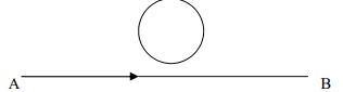
1. The current passing through the wire A, B is increasing. In which direction does the induced current flow in the closed loop.
2. State Faraday’s Law of electromagnetic induction. Express it mathematically.
3. State Lenz Law. On which law of conservation is it based?
4. How are eddy currents produced?
5. Power factor of an a.c. circuit is 0.5. What will be the phase difference between voltage and current in the circuit?
6. What is the significance of a Q-factor in a series LCR resonant circuit?
7. What is the principle of a.c. generator?
8. What is the power consumed in (i) purely inductive and (ii) purely capacitive a.c. circuits?
9. Draw the graph to show the variation of Xc with the frequency of the a.c. source used.
10. Which is the best method of reducing current in an a.c. circuit and why?
11. If the no of turns of a solenoid is doubled, keeping the other factors constant how does the selfinductance of the solenoid change?
12. Sketch the variation of inductive reactance and capacitive reactance with the frequency of a.c. source.
13. What is the frequency of direct current?
14. What is the relation between peak value and root mean square value of alternating e.m.f.?
15. What is the mean value of an alternating current?
16. When are the voltage and current in LCR-circuit in same phase?
17. a capacitor blocks d.c. Why?
18. The frequency of a.c. source is doubled. How do R, XL and Xc get affected?
19. Which is more dangerous than d.c. for the same value?
20. A lamp is connected in series with a capacitor. Predict your observation for d.c. and a.c. connections. What happens in each case if the capacitance is reduced?
21. What is the unit of L/R?
22. As soon as the current is switched on in a high voltage wire, the bird sitting on it flies away, Why?
23. Fig shows a bar magnet M falling under gravity through an air cored coil C. Plot a graph showing variation of induced e.m.f. E with time (t). What does the area enclosed by the E-t curve depict? M
24. A rectangular loop of wire is being withdrawn out of the magnetic field with velocity v. The magnetic field is perpendicular to the plane of paper. What will be the direction of induced current, if any, in the loop?
5 mark questions:-
25. Derive expression for self-inductance of a long air-cored solenoid of length l, radius r and having number of turns N.
26. What do you mean by mutual inductance of two nearby coils? Find an expression for mutual inductance of a solenoid-coil system.
27. Define the term capacitive reactance; show graphically the variation of capacitive reactance with frequency of applied voltage by angle π/2.
Describe briefly the principle, construction and working of a transformer. Why is its core laminated?
Important Questions for NCERT Class 12 Physics Electromagnetic Induction
Question. Faraday’s laws are consequence of conservation of
(a) energy
(b) energy and magnetic field
(c) charge
(d) magnetic field
Answer : A.
Question. Two coils of self inductance 2 mH and 8 mH are placed so close together that the effective flux in one coil is completely linked with the other.
The mutual inductance between these coils is
(a) 16 mH
(b) 10 mH
(c) 6 mH
(d) 4 mH
Answer : D
Question. A cycle wheel of radius 0.5 m is rotated with constant angular velocity of 10 rad/s in a region of magnetic field of 0.1 T which is perpendicular to the plane of the wheel. The EMF generated between its centre and the rim is
(a) 0.25 V
(b) 0.125 V
(c) 0.5 V
(d) zero
Answer : B
Question. A straight line conductor of length 0.4 m is moved with a speed of 7 m/s perpendicular to a magnetic field of intensity 0.9 Wb/m2. The induced e.m.f. across the conductor is
(a) 5.04 V
(b) 25.2 V
(c) 1.26 V
(d) 2.52 V
Answer : D
Question. A long solenoid of diameter 0.1 m has 2 × 10⁴ turns per meter. At the centre of the solenoid, a coil of 100 turns and radius 0.01 m is placed with its axis coinciding with the solenoid axis. The current in the solenoid reduces at a constant rate to 0 A from 4 A in 0.05 s. If the resistance of the coil is 10 p2 W, the total charge flowing through the coil during this time is
(a) 16 mC
(b) 32 mC
(c) 16p mC
(d) 32p mC
Answer : B
Question. The magnetic flux through a circuit of resistance R changes by an amount Df in a time Dt. Then the total quantity of electric charge Q that passes any point in the circuit during the time Dt is represented by
(a) Q = 1/R . ΔΦ /Δt
(b) Q = ΔΦ/R
(c) Q = ΔΦ /Δt
(d) Q= R.ΔΦ /Δt
Answer : B
Question. The total charge, induced in a conducting loop when
it is moved in magnetic field depends on
(a) the rate of change of magnetic flux
(b) initial magnetic flux only
(c) the total change in magnetic flux
(d) final magnetic flux only.
Answer : C
Question. The magnetic flux through a circuit of resistance R changes by an amount Df in a time Dt. Then the total quantity of electric charge Q that passes any point in the circuit during the time Dt is represented by
(a) Q = 1/R . ΔΦ//Δt
(b) Q = ΔΦ//R
(c) Q = ΔΦ//Δt
(d) Q = R .ΔΦ//Δt
Answer : B
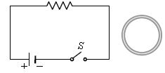
Question. A small loop lies outside a circuit. The key of the circuit is closed and opened alternately. The closed loop will show:
a. Clockwise pulse followed by another clockwise pulse
b. Anticlockwise pulse followed by another anticlockwise pulse
c. Anticlockwise pulse followed by a clockwise pulse
d. Clockwise pulse followed by an anticlockwise pulse
Answer : D
Question. A bar magnet is falling freely inside a long copper tube and a solenoid as shown in figure (i) and (ii) respectively then acceleration of magnet inside the copper tube and solenoid are respectively: (acceleration due to gravity = g)

a. g, g
b. Greater than g, lesser than g
c. Greater than g, g
d. Zero, lesser than g
Answer : D
Question. In which of the following devices, the eddy current effect is not used?
(a) electric heater
(b) induction furnace
(c) magnetic braking in train
(d) electromagnet .
Answer : A
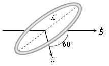
Question. A coil of area A = 0.5 m2 is situated in a uniform magnetic field B = 4.0 wb/m2 and area vector makes an angle of 60° with respect to the magnetic field as shown in figure. The value of the magnetic flux through the area A would be equal to:
a. 2 weber
b. 1 weber
c. 3 weber
d. 3/2 weber
Answer : B
Question. Consider the following figure, a uniform magnetic field of 0.2 T is directed along the positive x-axis. What is the magnetic flux through top surface of the figure?
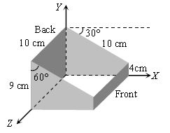
a. Zero
b. 0.8 m-wb
c. 1.0 m-wb
d. – 1.8 m-wb
Answer : C
Question. An ideal transformer does not vary the output:
a. energy
b. power
c. frequency
d. current
Answer : A, B, C
Question. Consider the arrangement shown in figure in which the north pole of a magnet is moved away from a thick conducting loop containing capacitor. Then excess positive charge will arrive on:
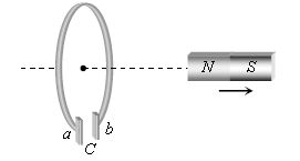
a. Plate a
b. Plate b
c. On both plates a and b
d. On neither a nor b plates
Answer : B
Question. Alternating current can be used for:
a. heating
b. lighting
c. electrolysis
d. generate mechanical energy
Answer : A, B, D
Question. A square loop of side 1m is placed in a perpendicular magnetic field. Half of the area of the loop inside the magnetic field. A battery of emf 10 V and negligible internal resistance is connected in the loop. The magnetic field changes with time according to relation B = 0.01 – 2t Tesla. The resultant emf in the loop will be:
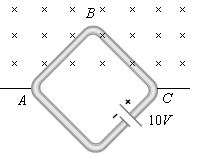
a. 1 V
b. 11 V
c. 10 V
d. 9 V
Answer : D
Question. Which of the following phenomenon cause loss of energy in a transformer?
a. heating
b. eddy currents
c. mechanical motion
d. hysteresis
Answer : A, B, D
Question. The core of the transformer is laminated to:
a. reduce the eddy currents
b. reduce self induction
c. increase the efficiency
d. decrease the weight of the transformer
Answer : A, C
Question. Which of the statements is/are true? Heat produced in a current-carrying conductor depends upon:
a. the time for which the current flows in the conductor
b. the resistance of the conductor
c. the strength of the current
d. the nature of current (A.C. or D.C.)
Answer : A, B, C
Question. Which of the followings does not decrease the efficiency of the transformer?
a. laminating the core
b. use of iron core
c. core made of material having narrow hysteresis loop
d. none of the above
Answer : A, B, C
Question. An alternating e.m.f. of frequency v ( = 1/2π√LC) is applied to a series LCR circuit. For this frequency of the applied e.m.f.
a. The circuit is at resonance and its impedance is made up only of a reactive part
b. The current in the circuit is in phase with the applied e.m.f. and the voltage across R equals this applied emf
c. The sum of the p.d.’s across the inductance and capacitance equals the applied e.m.f. which is 180° ahead of phase of the current in the circuit
d. The quality factor of the circuit is ωL / R or 1 / ωCRR and this is a measure of the voltage magnification (produced by the circuit at resonance) as well as the sharpness of resonance of the circuit
Answer : B, D
Assertion and Reason
Note: Read the Assertion (A) and Reason (R) carefully to mark the correct option out of the options given below:
a. If both assertion and reason are true and the reason is the correct explanation of the assertion.
b. If both assertion and reason are true but reason is not the correct explanation of the assertion.
c. If assertion is true but reason is false.
d. If the assertion and reason both are false.
e. If assertion is false but reason is true.
Question. Assertion: A rectangular loop and a circular loop are moved with a constant velocity from a region of magnetic field out into a field-free region. The field is normal to the loops. Then a constant emf will be induced in the circular loop and a time-varying emf will be induced in the rectangular loop.
Reason: The induced emf is constant if the magnetic flux changes at a constant rate.
Answer : D
Question. Assertion: The alternating current lags behind the e.m.f. by a phase angle of , π/2 when ac flows through an inductor.
Reason: The inductive reactance increases as the frequency of ac source decreases.
Answer : E
Question. Assertion: A coil is connected in series with a bulb and this combination is connected to an a.c. source. If an iron core is inserted in the coil, the brightness of the bulb will be reduced.
Reason: When an iron core is inserted in the coil, its inductance decreases.
Answer : C
Question. Assertion: Magnetic flux can produce induced e.m.f.
Reason: Faraday established induced e.m.f. experimentally.
Answer : E
Question. Assertion: A capacitor of suitable capacitance can be used in an ac circuit in place of the choke coil.
Reason: A capacitor blocks dc and allows ac only.
Answer : B
Question. Assertion: A magnetised iron bar is dropped vertically through a hollow region of a thick cylindrical shell made of copper. The bar will fall with an acceleration less than g, the acceleration due to gravity.
Reason: The emf induced in the bar causes a retarding force to act on the falling bar.
Answer : A
Question. Assertion: If the frequency of alternating current in an ac circuit consisting of an inductance coil is increased then current gets decreased.
Reason: The current is inversely proportional to frequency of alternating current.
Answer : A
Question. Assertion: When capacitive reactance is smaller than the inductive reactance in LCR current, e.m.f. leads the current.
Reason: The phase angle is the angle between the alternating e.m.f. and alternating current of the circuit.
Answer : B
Question. Assertion: An ac generator is based on the phenomenon of self-induction
Reason: In single coil, we consider self-induction only.
Answer : E
Question. Assertion: In series LCR circuit resonance can take place.
Reason: Resonance takes place if inductance and capacitive reactance’s are equal and opposite.
Answer : A
Question. Assertion: Chock coil is preferred over a resistor to adjust current in an ac circuit.
Reason: Power factor for inductance is zero.
Answer : A
Question. Assertion: A bulb connected in series with a solenoid is connected to ac source. If a soft iron core is introduced in the solenoid, the bulb will glow brighter.
Reason: On introducing soft iron core in the solenoid, the inductance increases.
Answer : E
Question. Assertion: Acceleration of a magnet falling through a long solenoid decreases.
Reason: The induced current produced in a circuit always flow in such direction that it opposes the change or the cause the produced it.
Answer : A
Question. Assertion: An aircraft flies along the meridian, the potential at the ends of its wings will be the same.
Reason: Whenever there is change in the magnetic flux e.m.f. induces.
Answer : E
Question. Assertion: An alternating current does not show any magnetic effect.
Reason: Alternating current varies with time.
Answer : B
Section A: Conceptual and application type questions
Question 1. What is the power dissipated in an AC circuit in which voltage and current are given by V = 230sin(ωt+π/2) and I = 10 sinωt? Give reason
Answer: The average power dissipated in an AC circuit is given by the formula:
\( P = V_{rms} I_{rms} \cos\phi \)
where \( \phi \) is the phase difference between the alternating voltage and the alternating current.
Given:
\( V = 230 \sin(\omega t + \pi/2) \)
\( I = 10 \sin(\omega t) \)
This shows that the phase difference is \( \phi = \frac{\pi}{2} \) (or \( 90^\circ \)).
Substituting this value into the power formula:
\( P = V_{rms} I_{rms} \cos\left(\frac{\pi}{2}\right) \)
Since \( \cos\left(\frac{\pi}{2}\right) = 0 \):
\( P = 0 \)
Reason: The voltage and current are out of phase by \( 90^\circ \). In such a purely reactive circuit, no real power is dissipated.
In simple words: The power used is zero because the voltage and current are out of sync by exactly 90 degrees. When they are offset like this, the circuit stores energy and releases it back without actually consuming any net power.
Exam Tip: Always state the power formula \( P = V_{rms} I_{rms} \cos\phi \) and explicitly show that \( \cos(90^\circ) = 0 \) to get full marks.
Question 2. Two identical loops ,one of copper and other of constantan ,are removed from a magnetic field within the same time interval. In which loop will the induced current be greater? Justify.
Answer: The induced electromotive force (emf) is determined by the rate of change of magnetic flux:
\( e = -\frac{d\Phi}{dt} \)
Since both loops are identical in dimensions and are removed from the same magnetic field within the same time frame, the induced emf \( e \) in both loops is equal.
However, the induced current is given by Ohm's law:
\( I = \frac{e}{R} \)
Since the resistivity of copper is significantly lower than that of constantan (an alloy), the electrical resistance \( R \) of the copper loop is much smaller. Consequently, the induced current will be greater in the copper loop.
In simple words: Both loops get the exact same voltage because they are moved out of the magnetic field in the same way. But because copper conducts electricity much better than constantan (it has lower resistance), a larger current will flow through the copper loop.
Exam Tip: Be careful to state that the induced emf is the same for both, but the induced current differs because of the difference in their material resistivities.
Question 3. A conducting coil is moved relative to a magnetic field .Will there be induced emf and induced current always? Justify
Answer: No, they will not always be present.
Justification:
1. **Induced EMF:** An electromotive force (emf) is induced only if the relative motion between the coil and the magnetic field results in a change in the magnetic flux linked with the coil over time (\( \frac{d\Phi}{dt} \neq 0 \)). If the coil moves in a way that keeps the magnetic flux constant (such as moving parallel to uniform magnetic field lines), no emf is induced.
2. **Induced Current:** An induced current is produced only if both conditions are met: there is a change in the linked magnetic flux (inducing an emf) and the coil forms a closed conducting loop. If the coil is open, an emf is induced across its terminals, but no current flows.
In simple words: No. You only get voltage if the movement actually changes the amount of magnetic field passing through the coil. Even then, you only get an electric current flowing if the wire loop is fully closed with no breaks.
Exam Tip: To get full marks, split your justification into two parts: one for the conditions required to induce emf, and another for the closed-loop requirement of the induced current.
Question 4. What is the significance of power factor in i) electrical appliances ii) transmission of electric power?
Answer: The power factor, \( \cos\phi = \frac{R}{Z} \), is highly significant in electrical systems:
**i) In Electrical Appliances:**
A low power factor means the appliance must draw a larger current \( I = \frac{P}{V \cos\phi} \) to operate at its rated power \( P \). This higher current leads to increased heat dissipation (\( I^2 R \) losses) in the appliance's internal wiring, necessitating thicker, more expensive copper wires and reducing overall efficiency.
**ii) In Transmission of Electric Power:**
To transmit a given amount of power \( P \) at a voltage \( V \), the line current is \( I = \frac{P}{V \cos\phi} \). If the power factor \( \cos\phi \) is low, a much larger current must be sent through the transmission lines. This causes massive power losses (\( I^2 R \) ) along the transmission cables and requires thicker cables, increasing costs. Therefore, power companies require consumers (especially industries) to keep their power factor close to 1.
In simple words: i) For appliances, a low power factor means they have to draw more current to do the same job, which heats up the wires and wastes energy. ii) For power lines, a low power factor forces the power grid to send extra current, causing huge energy losses in the long transmission wires.
Exam Tip: Use the formula \( I = \frac{P}{V \cos\phi} \) to explain how a smaller power factor \( \cos\phi \) leads to a larger current \( I \), causing more \( I^2 R \) heating losses in both cases.
Question 5. Two identical bar magnets are dropped from the same height simultaneously , one falls through a copper tube and the other falls through air, will they reach ground at the same time? Justify.
Answer: No, they will not reach the ground simultaneously. The magnet falling through the copper tube will arrive later.
**Justification:**
As the magnet falls through the conducting copper tube, the changing magnetic flux induces eddy currents in the tube's walls. According to Lenz's law, these induced eddy currents generate a magnetic field that opposes the motion of the falling magnet. This creates an upward electromagnetic retarding force, which reduces the net downward acceleration of the magnet below \( g \). On the other hand, the magnet falling through the air experiences only negligible air resistance, falling with an acceleration nearly equal to \( g \).
In simple words: No. The magnet falling through the copper tube will take longer to hit the ground. This is because the falling magnet induces electric currents in the copper walls, which push back against the magnet and slow its fall, while the other magnet falls freely through the air.
Exam Tip: The key term examiners look for is 'eddy currents' and the application of 'Lenz's law' to explain the electromagnetic damping/retarding force.
Question 6. The south pole of a magnet is brought near a conducting loop. What is the direction of induced current as observed by a person on the other side of the loop?
Answer: According to Lenz's law, the face of the conducting loop closer to the approaching South pole must develop a South pole to oppose the magnet's motion. As viewed by an observer on the magnet's side, a South pole corresponds to a clockwise induced current.
Consequently, for a person looking at the loop from the other side, the direction of the induced current will appear to be anti-clockwise (counter-clockwise).
In simple words: Lenz's law says the loop will try to push the approaching south pole away by making its own south pole on that side. This requires a clockwise current on the front side, which looks anti-clockwise to someone looking from the back side.
Exam Tip: Be very careful about the observer's perspective. While the current is clockwise from the magnet's side, it is anti-clockwise from the opposite side.
Question 7. A radio frequency choke is air cored coil where as an audio frequency choke is iron cored. Give reason.
Answer: The inductive reactance of a choke coil is given by the relation:
\( X_L = 2\pi f L \)
where \( f \) is the frequency and \( L \) is the inductance of the coil.
1. **For Radio Frequencies (RF):** Since \( f \) is extremely high (in the megahertz range), even a small inductance \( L \) is sufficient to produce a large reactance to choke the current. An air-core coil provides a low but adequate inductance, while avoiding magnetic hysteresis and eddy current losses associated with iron cores at high frequencies.
2. **For Audio Frequencies (AF):** Since \( f \) is relatively low (in the hertz/kilohertz range), a very large inductance \( L \) is required to generate a high enough reactance to choke the current. Introducing an iron core drastically increases the magnetic permeability and therefore the inductance of the coil, making it effective for AF.
In simple words: Chokes block electricity using the formula \( X_L = 2\pi f L \). Since radio waves have super-high frequencies, a simple air-core coil has enough inductance to block them. But audio waves have low frequencies, so we need an iron core to boost the coil's inductance and make it strong enough to block them.
Exam Tip: Relate the choice of core directly to the formula \( X_L = 2\pi f L \) to demonstrate why low frequencies require high inductance.
Question 8. How does the selfinductanceof an air core coil change, when i) the number of turns in the coil is decreased? ii) an iron rod is introduced in the coil?
Answer: The self-inductance of a solenoid is given by the formula:
\( L = \frac{\mu_0 \mu_r N^2 A}{l} \)
where \( N \) is the number of turns, \( \mu_r \) is the relative permeability of the core, \( A \) is the cross-sectional area, and \( l \) is the length.
**i) When the number of turns is decreased:**
Since self-inductance is directly proportional to the square of the number of turns (\( L \propto N^2 \)), decreasing the number of turns will cause the self-inductance of the coil to decrease.
**ii) When an iron rod is introduced inside the coil:**
An iron rod has a high relative magnetic permeability (\( \mu_r \gg 1 \)). Since \( L \propto \mu_r \), introducing the iron rod will cause the self-inductance of the coil to increase significantly.
In simple words: i) Reducing the number of turns in a coil weakens its magnetic properties, so the self-inductance decreases. ii) Putting an iron rod inside makes it much easier for magnetic fields to form, which increases the self-inductance by a large amount.
Exam Tip: State the formula \( L = \frac{\mu_0 \mu_r N^2 A}{l} \) first, as it allows you to easily justify both changes.
Question 9. A bismuth rod is introduced in a solenoid carrying current ,how do i) its self inductance ii) emf induced in the solenoid change?
Answer: Bismuth is a diamagnetic material, which means its relative magnetic permeability \( \mu_r \) is slightly less than 1 (\( \mu_r < 1 \)).
**i) Change in Self-Inductance:**
Since self-inductance \( L \) is directly proportional to the relative permeability of the core material inside the solenoid (\( L \propto \mu_r \)), introducing a bismuth rod (which has a lower permeability than air) will slightly decrease the self-inductance of the solenoid.
**ii) Change in Induced EMF:**
The induced electromotive force (emf) is proportional to the self-inductance:
\( e = -L \frac{dI}{dt} \)
Since the self-inductance \( L \) decreases, the magnitude of the induced emf in the solenoid will also decrease.
In simple words: Bismuth is diamagnetic, which means it slightly repels magnetic fields. Placing it in the coil decreases the coil's self-inductance, which in turn reduces the voltage induced when the current changes.
Exam Tip: The key concept is identifying bismuth as a diamagnetic material with \( \mu_r < 1 \), which is why both inductance and induced emf decrease.
Question 10. A copper coil L wound on a soft iron core and a lamp B is connected to a battery E through a tap key K. when the key is closed, the lamp glows dimly .But when the key is suddenly opened , the lamp flashes for an instant to much greater brightness . Explain.
Answer: This phenomenon is explained by self-induction in the coil:
1. **When the key is closed:** The copper coil wound on a soft iron core has a very low DC electrical resistance compared to the lamp. In the steady-state, most of the current from the battery flows through the low-resistance coil, leaving only a small fraction of the current to flow through the lamp. This is why the lamp glows dimly.
2. **When the key is suddenly opened:** The current flowing through the circuit rapidly falls to zero. This extremely fast rate of decay (\( \frac{dI}{dt} \to \infty \)) inside the highly inductive coil induces a very large self-induced electromotive force (back emf) in it. This massive induced voltage forces a strong surge of current to pass through the lamp, which forms a closed loop with the coil. This causes the lamp to flash with a much greater brightness for an instant until the energy stored in the coil's magnetic field is fully dissipated.
In simple words: When the key is closed, most of the electricity takes the easy path through the low-resistance coil, bypassing the lamp and leaving it dim. But when you break the circuit, the collapsing magnetic field in the coil generates a sudden, massive burst of voltage that surges through the lamp, making it flash brightly for a split second.
Exam Tip: Focus on explaining the two states: the steady-state division of current based on resistance, and the transient state where a high \( \frac{dI}{dt} \) creates a large back emf.
Question 11. In any ac circuit ,is the applied instantaneous voltage equal to the algebraic sum of the instantaneous voltages across the series elements of the circuit ?
Answer: Yes, the applied instantaneous voltage is always equal to the algebraic sum of the instantaneous voltages across the series elements of the circuit.
This is because Kirchhoff's Loop Rule, which is based on the law of conservation of energy, holds true at any given instant in time:
\( v(t) = v_R(t) + v_L(t) + v_C(t) \)
*(Note: While the rms or peak voltages of the series components must be added vectorially using phasor diagrams because they are out of phase, their instantaneous values always add up algebraically at any specific moment.)*
In simple words: Yes. At any single moment, the total voltage you apply is exactly equal to the sum of the voltages across each component. This is because energy is always conserved at any split second.
Exam Tip: Crucially distinguish between "instantaneous voltage" (which adds up algebraically) and "rms/peak voltage" (which must be added vectorially using phasor algebra) to impress the examiner.
Question 12. A conducting loop of area A and resistance R is placed perpendicular to the magnetic field B. The loop is withdrawn completely from the field. Derive an expression for induced charge that flows through any cross section of the wire
Answer: Let us derive the expression for the total induced charge:
According to Faraday's law of electromagnetic induction, the induced electromotive force (emf) is:
\( e = -\frac{d\Phi}{dt} \)
The induced current \( I \) flowing through a loop of electrical resistance \( R \) is:
\( I = \frac{e}{R} = -\frac{1}{R} \frac{d\Phi}{dt} \)
Since current is the rate of flow of charge (\( I = \frac{dq}{dt} \)), we can write:
\( \frac{dq}{dt} = -\frac{1}{R} \frac{d\Phi}{dt} \)
Integrating both sides to find the total charge \( q \) that flows through the wire:
\( q = \int dq = -\frac{1}{R} \int_{\Phi_1}^{\Phi_2} d\Phi \)
\( q = \frac{\Phi_1 - \Phi_2}{R} = \frac{\Delta\Phi}{R} \)
Given:
- Initial magnetic flux \( \Phi_1 = B A \) (since the loop of area \( A \) is perpendicular to the field \( B \)).
- Final magnetic flux \( \Phi_2 = 0 \) (since the loop is completely withdrawn).
Substituting these values into the charge equation:
\( q = \frac{B A - 0}{R} \)
\( \implies q = \frac{B A}{R} \)
In simple words: The voltage created is the rate of flux change, and dividing this by resistance gives the current. By multiplying current by time, we find that the total electrical charge that flows depends only on the total change in magnetic flux divided by the resistance: \( q = \frac{BA}{R} \).
Exam Tip: Emphasize that the total induced charge depends solely on the change in magnetic flux and the resistance of the loop, and is completely independent of the time taken to withdraw the loop.
Question 13. The south pole of a magnet is brought near a conducting loop. What is the direction of induced current as observed by a person on the other side of the loop?
Answer: According to Lenz's law, when a South pole is moved toward a conducting loop, the face of the loop nearest to the magnet will develop a South pole to oppose the magnet's approach. To an observer standing on the magnet's side, this corresponds to a clockwise current.
Therefore, an observer situated on the opposite (other) side of the loop will see the current flowing in the anti-clockwise direction.
In simple words: Lenz's law says the loop will try to push the approaching south pole away by making its own south pole on that side. This requires a clockwise current on the front side, which looks anti-clockwise to someone looking from the back side.
Exam Tip: Specify both perspectives clearly (the magnet's side vs the opposite side) to prevent any ambiguity in your answer.
Question 14. A bulb B and an inductor L are connected in series to the AC mains. The bulb glows with some brightness. How will the glow of the bulb change when a i) a soft iron core ii) bismuth core is introduced inside the inductor? Give reasons.
Answer: The brightness of the bulb depends on the rms current \( I \) flowing through the series RL circuit, which is given by:
\( I = \frac{V}{\sqrt{R^2 + X_L^2}} \)
where \( R \) is the resistance of the bulb and \( X_L = \omega L \) is the inductive reactance of the inductor.
**i) When a soft iron core is introduced:**
Soft iron is a ferromagnetic material that drastically increases the self-inductance \( L \) of the coil. As \( L \) increases, the inductive reactance \( X_L \) increases, which increases the total impedance of the circuit. This reduces the current flowing through the circuit, causing the glow of the bulb to decrease (become dimmer).
**ii) When a bismuth core is introduced:**
Bismuth is a diamagnetic material, which slightly decreases the self-inductance \( L \) of the coil. As \( L \) decreases, the inductive reactance \( X_L \) decreases, reducing the total impedance of the circuit. This slightly increases the current, causing the glow of the bulb to increase slightly (become brighter).
In simple words: The brightness of the bulb depends on how much current gets through. i) Inserting a soft iron core increases the inductor's resistance to AC, reducing the current and making the bulb dimmer. ii) Inserting a bismuth core slightly lowers the inductor's opposition, allowing slightly more current to flow and making the bulb a bit brighter.
Exam Tip: Use the formula for impedance \( Z = \sqrt{R^2 + (\omega L)^2} \) to show how changing \( L \) directly affects the current \( I \) and bulb brightness.
Question 15. A coil of number of turns N, area A, is rotated at a constant angular speed w, in a uniform magneticfield B, and connected to a resistor R. Deduce expressions for : (i) Maximum emf induced in the coil (ii) Power dissipation in the coil.
Answer: Let us derive the expressions:
At any instant \( t \), the magnetic flux \( \Phi \) linked with the rotating coil of \( N \) turns and area \( A \) is:
\( \Phi = N B A \cos(\omega t) \)
According to Faraday's law, the induced electromotive force (emf) \( e \) is:
\( e = -\frac{d\Phi}{dt} = -\frac{d}{dt} [N B A \cos(\omega t)] \)
\( e = N B A \omega \sin(\omega t) \)
**(i) Maximum EMF Induced in the Coil:**
The induced emf reaches its maximum value when \( \sin(\omega t) = 1 \). Therefore, the peak (maximum) emf is:
\( e_{max} = N B A \omega \)
**(ii) Power Dissipation in the Coil:**
The power dissipated \( P \) as heat in the resistor \( R \) is given by:
\( P = \frac{e_{rms}^2}{R} \)
The root-mean-square (rms) value of the induced emf is:
\( e_{rms} = \frac{e_{max}}{\sqrt{2}} = \frac{N B A \omega}{\sqrt{2}} \)
Substituting \( e_{rms} \) into the power equation:
\( P = \frac{\left(\frac{N B A \omega}{\sqrt{2}}\right)^2}{R} \)
\( \implies P = \frac{(N B A \omega)^2}{2 R} \)
In simple words: The voltage generated fluctuates like a sine wave. i) The highest voltage it hits is \( N B A \omega \). ii) To find the average power dissipated in the resistor, we use the root-mean-square voltage, which gives a power loss of \( \frac{(N B A \omega)^2}{2 R} \).
Exam Tip: In part (ii), do not use the maximum emf \( e_{max} \) directly to find average power. You must use the rms value \( e_{rms} = \frac{e_{max}}{\sqrt{2}} \) to get the correct average power.
Question 16. A bulb B and a capacitor C are connected in series to the AC mains. The bulb glows with some brightness. How will the glow of the bulb change when a dielectric slab is introduced between the plates of the capacitor? Give reasons.
Answer: The brightness of the bulb depends on the rms current \( I \) flowing through the series RC circuit:
\( I = \frac{V}{\sqrt{R^2 + X_C^2}} \)
where \( R \) is the bulb's resistance and \( X_C = \frac{1}{\omega C} \) is the capacitive reactance.
When a dielectric slab of dielectric constant \( K \) is inserted between the plates of the capacitor, its capacitance \( C \) increases to \( K C \).
According to the formula \( X_C = \frac{1}{\omega C} \), an increase in capacitance causes a decrease in capacitive reactance \( X_C \). This reduces the total impedance \( Z \) of the circuit, allowing a larger current to flow. As a result, the glow of the bulb increases (becomes brighter).
In simple words: A capacitor opposes AC current with a resistance called capacitive reactance. Inserting a dielectric slab boosts the capacitor's storage capacity, which lowers its reactance. This lets more current flow through, making the bulb shine brighter.
Exam Tip: State the two-step dependency clearly: first, how the dielectric increases \( C \), and second, how a larger \( C \) decreases \( X_C \), thereby increasing the current.
Question 17. Mark the direction of induced current in the coil PQRS. State the rule used to find the direction of induced current. What would be the direction of induced current if the direction of magnetic field is reversed?
Answer: Based on Lenz's law, we can determine the direction of the induced current:
1. **Direction of Induced Current:**
As the rectangular coil PQRS is pulled out of the magnetic field (directed into the page) to the left, the magnetic flux pointing into the page decreases. To oppose this decrease, the induced current must generate its own magnetic field pointing into the page. According to the right-hand grip rule, this requires a clockwise current, flowing along the path P-Q-R-S-P.
2. **Rule Used:**
The rule used to find the direction is Lenz's Law (which states that the induced current opposes the change in magnetic flux that creates it).
3. **If the Magnetic Field is Reversed:**
If the magnetic field originally pointed out of the page, withdrawing the loop would cause a decrease in outward flux. The induced current would try to oppose this by creating an outward-pointing magnetic field, which requires an anti-clockwise current flowing along the path P-S-R-Q-P.
In simple words: When pulling the loop out, it loses magnetic field lines pointing into the page. To fight this loss, it creates its own clockwise current to push more lines in. If the field were pointing out of the page instead, the current would flow counter-clockwise to fight the loss of outward lines.
Exam Tip: Explicitly cite both the direction (clockwise) and the path (P-Q-R-S-P) to make your answer completely clear to the examiner.
Question 18. The figure shows a circular coil and a conductor AB carrying current from A to B. If the current is i) decreasing ii) increasing find the direction of induced current in the circular coil.
Answer: Using the right-hand grip rule, the current flowing from left to right (from A to B) in the straight conductor produces a magnetic field that points out of the plane of the page in the region above the wire, where the circular coil is located.
**i) If the current is decreasing:**
The outward magnetic flux linked with the circular coil is decreasing. According to Lenz's law, the induced current in the coil will oppose this decrease by generating a magnetic field that also points out of the page. This requires an anti-clockwise induced current.
**ii) If the current is increasing:**
The outward magnetic flux linked with the circular coil is increasing. To oppose this increase, the induced current in the coil must generate a magnetic field that points into the page. This requires a clockwise induced current.
In simple words: The wire's current creates a magnetic field pointing out of the page through the circle. i) If the wire's current fades, the circle tries to keep the field strong by flowing anti-clockwise. ii) If the wire's current gets stronger, the circle fights the increase by flowing clockwise.
Exam Tip: State the direction of the initial magnetic field (out of the page) clearly before analyzing the two cases to ensure your logic is completely solid.
Question 19. Draw a labelled circuit arrangement showing the windings of primary and secondary coil in atransformer. Explain the underlying principle and working of a step-up transformer. Write anytwo major sources of energy loss in this device.
Answer: **Labelled Diagram of a Step-Up Transformer:**
**Underlying Principle:**
A transformer works on the principle of **mutual induction**. When a changing electric current flows through one coil (primary), it produces a changing magnetic flux in the common iron core, which in turn induces an electromotive force (emf) across the neighboring coil (secondary).
**Working of a Step-Up Transformer:**
When an alternating voltage \( V_p \) is applied across the primary coil, it creates an alternating magnetic flux in the laminated soft iron core. This changing flux is linked with the secondary coil, inducing an alternating voltage \( V_s \) across it.
According to Faraday's law:
\( \frac{V_s}{V_p} = \frac{N_s}{N_p} \)
In a step-up transformer, the secondary coil is designed with more turns than the primary coil (\( N_s > N_p \)). Consequently, the output voltage \( V_s \) is scaled up and becomes greater than the input voltage \( V_p \).
**Two Major Sources of Energy Loss:**
1. **Copper Loss:** This is the loss of energy as heat (\( I^2 R \)) inside the copper windings due to their inherent electrical resistance.
2. **Iron Loss (Eddy Current Loss):** The alternating magnetic flux induces swirling eddy currents inside the iron core, which generates heat. This is minimized by using a laminated iron core.
In simple words: A step-up transformer uses mutual induction to raise voltage. By winding more turns of wire on the output side than the input side, the changing magnetic field boosts the output voltage. Its two major energy losses are heat generated in the copper wires and heat caused by swirling eddy currents in the iron core.
Exam Tip: Clearly draw the primary with fewer turns and the secondary with more turns to correctly depict a "step-up" transformer.
Question 20. A step-up transformer converts a low voltage into high voltage. Does it not violate theprinciple of conservation of energy? Explain.
Answer: No, the operation of a step-up transformer does not violate the law of conservation of energy.
**Explanation:**
According to the conservation of energy, the output power of an ideal transformer must equal its input power:
\( V_p I_p = V_s I_s \)
When a step-up transformer increases the voltage on the secondary side (\( V_s > V_p \)), it simultaneously decreases the current on that side by the exact same proportion (\( I_s < I_p \)). Therefore, the total electrical energy delivered per second remains constant (and actually decreases slightly in real-world transformers due to efficiency losses), fully complying with the principle of conservation of energy.
In simple words: No. Even though it boosts the voltage, it cuts the current down by the same amount. Since power is voltage multiplied by current, the total energy per second stays the same, so no energy is created out of nowhere.
Exam Tip: State the ideal power equation \( V_p I_p = V_s I_s \) to mathematically demonstrate how a voltage boost is balanced by a current drop.
Question 21. Define the quality factor in an a.c. circuit. Why should the quality factor have high valuein receiving circuits? Name the factors on which it depends.
Answer: **Definition:**
The Quality Factor (Q-factor) of a series resonant LCR circuit is a dimensionless parameter that measures the sharpness of its resonance. It is defined as the ratio of the resonant angular frequency (\( \omega_0 \)) to the bandwidth of the circuit (\( 2\Delta\omega \)):
\( Q = \frac{\omega_0}{2\Delta\omega} = \frac{1}{R}\sqrt{\frac{L}{C}} \)
**Significance in Receiving Circuits:**
Receiving circuits (such as radio and television tuners) must have a high Q-factor to ensure high selectivity. A higher Q-factor results in a narrower bandwidth and a sharper resonance peak. This allows the tuner to precisely select the desired station's frequency while strongly blocking closely spaced signals from other broadcasting stations, preventing overlaps and interference.
**Factors on Which it Depends:**
As shown by the formula \( Q = \frac{1}{R}\sqrt{\frac{L}{C}} \), the Quality Factor depends on:
1. The electrical resistance \( R \) of the circuit (inversely proportional).
2. The self-inductance \( L \) of the coil (directly proportional).
3. The capacitance \( C \) of the capacitor (inversely proportional).
In simple words: The Q-factor measures how sharp and focused a circuit's tuning is. A high Q-factor is needed in radios so you can tune into one specific station clearly without other stations bleeding into your audio. It depends on the circuit's resistance, inductance, and capacitance.
Exam Tip: The key term is "selectivity". Make sure to explain that a higher Q-factor means sharper resonance, which is essential for separating adjacent signals.
Question 22. Derive an expression for the average power consumed in a series LCR circuit connected toa.c. source in which the phase difference between the voltage and the current in the circuitis Φ.
Answer: Let the alternating voltage applied to the series LCR circuit be:
\( V = V_0 \sin(\omega t) \)
Let the resulting alternating current lag behind the voltage by a phase angle \( \Phi \):
\( I = I_0 \sin(\omega t - \Phi) \)
The instantaneous power \( P \) delivered by the AC source is:
\( P = V \times I = V_0 I_0 \sin(\omega t) \sin(\omega t - \Phi) \)
Using the trigonometric identity \( \sin A \sin B = \frac{1}{2}[\cos(A-B) - \cos(A+B)] \):
\( P = \frac{V_0 I_0}{2} [\cos(\omega t - (\omega t - \Phi)) - \cos(\omega t + \omega t - \Phi)] \)
\( P = \frac{V_0 I_0}{2} [\cos\Phi - \cos(2\omega t - \Phi)] \)
The average power \( P_{avg} \) consumed over a complete cycle is the time-average of this instantaneous power:
\[ P_{avg} = \frac{1}{T} \int_{0}^{T} P \, dt = \frac{V_0 I_0}{2T} \int_{0}^{T} [\cos\Phi - \cos(2\omega t - \Phi)] \, dt \]
Since the time-average of the term \( \cos(2\omega t - \Phi) \) over a full cycle is zero:
\[ P_{avg} = \frac{V_0 I_0}{2} \cos\Phi \]
This can be written as:
\( P_{avg} = \left(\frac{V_0}{\sqrt{2}}\right) \left(\frac{I_0}{\sqrt{2}}\right) \cos\Phi \)
\( \implies P_{avg} = V_{rms} I_{rms} \cos\Phi \)
In simple words: By multiplying the formulas for voltage and current and taking their average over a full cycle, we find that the average power is the RMS voltage times the RMS current, multiplied by the power factor \( \cos\Phi \).
Exam Tip: Ensure you write down the trigonometric identity clearly as a step, as this makes the math easy to follow and guarantees full marks.
Section B: Numerical problems
Question 1. Calculate the (i) impedance, (ii) wattless current of the given a.c. circuit. 2008
Answer: **Given parameters from the circuit diagram:**
Voltage drop across the capacitor, \( V_C = 40\text{ V} \)
Voltage drop across the resistor, \( V_R = 30\text{ V} \)
rms current in the circuit, \( I_{rms} = 2\text{ A} \)
**(i) Calculation of Impedance (\( Z \)):**
The total rms voltage \( V_{rms} \) across the series RC circuit is:
\( V_{rms} = \sqrt{V_R^2 + V_C^2} = \sqrt{30^2 + 40^2} = \sqrt{900 + 1600} = 50\text{ V} \)
Using Ohm's law, the impedance \( Z \) is:
\( Z = \frac{V_{rms}}{I_{rms}} = \frac{50\text{ V}}{2\text{ A}} = 25\,\Omega \)
**(ii) Calculation of Wattless Current:**
The phase angle \( \phi \) between the voltage and the current is given by:
\( \tan\phi = \frac{V_C}{V_R} = \frac{40}{30} = \frac{4}{3} \)
This gives:
\( \sin\phi = \frac{4}{5} = 0.8 \)
The wattless component of the current is:
\( I_{wattless} = I_{rms} \sin\phi = 2\text{ A} \times 0.8 = 1.6\text{ A} \)
In simple words: i) The combined voltage of the circuit is 50 volts. Dividing this by the 2-ampere current gives an impedance of 25 ohms. ii) The current component that does not consume any power is \( I \sin\phi \), which works out to 1.6 amperes.
Exam Tip: To find the total voltage \( V_{rms} \), remember that you cannot simply add the AC voltages algebraically (\( 30 + 40 = 70 \) is incorrect). You must use the vector addition formula: \( V = \sqrt{V_R^2 + V_C^2} \).
Question 2. A jet plane is travelling west at 450 ms- 1 . If the horizontal component of earth’s magnetic field atthat place is 4 X 10- 4 tesla and the angle of dip is 30°, find the emf induced between the ends ofwings having a span of 30 m.
Answer: **Given parameters:**
Speed of the jet plane, \( v = 450\text{ m/s} \)
Horizontal component of the Earth's magnetic field, \( B_h = 4 \times 10^{-4}\text{ T} \)
Angle of dip, \( \delta = 30^\circ \)
Wing span (length), \( l = 30\text{ m} \)
The wings of the horizontally flying plane cut across the vertical component of the Earth's magnetic field (\( B_v \)).
The vertical component \( B_v \) is given by:
\( B_v = B_h \tan\delta = (4 \times 10^{-4}\text{ T}) \times \tan 30^\circ = \frac{4 \times 10^{-4}}{\sqrt{3}}\text{ T} \approx 2.31 \times 10^{-4}\text{ T} \)
The induced electromotive force (emf) between the wingtips is:
\( e = B_v l v = (2.31 \times 10^{-4}\text{ T}) \times 30\text{ m} \times 450\text{ m/s} \)
\( e \approx 3.12\text{ V} \)
In simple words: As the jet flies, its wings cut through the vertical part of the Earth's magnetic field, which is about \( 2.31 \times 10^{-4} \) teslas. This creates an induced voltage of 3.12 volts across the tips of the wings.
Exam Tip: The plane cuts the vertical component of the Earth's magnetic field. Always calculate \( B_v = B_h \tan\delta \) first before applying the motional emf formula \( e = B v l \).
Question 3. How much current is drawn by the primary coil of a transformer which steps down 220 V to 22 Vto operate device with an impedance of 220 ohm ?
Answer: **Given parameters:**
Primary voltage, \( V_p = 220\text{ V} \)
Secondary voltage, \( V_s = 22\text{ V} \)
Impedance of the device (load), \( Z_s = 220\,\Omega \)
First, calculate the current \( I_s \) flowing in the secondary circuit using Ohm's law:
\( I_s = \frac{V_s}{Z_s} = \frac{22\text{ V}}{220\,\Omega} = 0.1\text{ A} \)
Assuming an ideal transformer, the power in the primary coil is equal to the power in the secondary coil:
\( V_p I_p = V_s I_s \)
Solving for the primary current \( I_p \):
\( I_p = \frac{V_s I_s}{V_p} = \frac{22\text{ V} \times 0.1\text{ A}}{220\text{ V}} \)
\( I_p = 0.01\text{ A} \)
In simple words: The device on the output side draws 0.1 amperes of current at 22 volts. Because the transformer steps down the voltage by a factor of 10, the input side only needs to draw a tiny current of 0.01 amperes.
Exam Tip: Remember to use the ideal transformer efficiency assumption (\( V_p I_p = V_s I_s \)) to relate the primary and secondary currents.
Question 4. In the circuit given, calculate i) the capacitance C of the capacitor , if the power factor of the circuit is unity and ii) also calculate the Q –factor of the circuit .Take ν =50Hz
Answer: **Given parameters from the circuit diagram:**
Inductance, \( L = 200\text{ mH} = 0.2\text{ H} \)
Resistance, \( R = 10\,\Omega \)
Frequency, \( f = 50\text{ Hz} \)
**i) Calculation of Capacitance (\( C \)):**
A power factor of unity (\( \cos\phi = 1 \)) indicates that the circuit is in resonance, where the inductive reactance equals the capacitive reactance:
\( X_L = X_C \implies 2\pi f L = \frac{1}{2\pi f C} \)
Solving for \( C \):
\( C = \frac{1}{4\pi^2 f^2 L} \)
\( C = \frac{1}{4 \times (3.1416)^2 \times (50\text{ Hz})^2 \times 0.2\text{ H}} \)
\( C \approx 5.07 \times 10^{-5}\text{ F} = 50.7\,\mu\text{F} \)
**ii) Calculation of the Quality Factor (Q-factor):**
The Q-factor of the series resonant circuit is:
\( Q = \frac{\omega_0 L}{R} = \frac{2\pi f L}{R} \)
\( Q = \frac{2 \times 3.1416 \times 50 \text{ Hz} \times 0.2 \text{ H}}{10\,\Omega} \)
\( Q \approx 6.28 \)
In simple words: i) For the power factor to be 1, the circuit must be at resonance, which means we need a capacitance of 50.7 microfarads. ii) The Quality factor of this circuit is 6.28.
Exam Tip: When the power factor is stated as 'unity', it is a clue that the circuit is at resonance, allowing you to use the resonance condition \( X_L = X_C \).
Question 5. In a series R-C circuit, R =30Ω ,C= 0.25µF, V= 100V and ω = 10000 rad/s. Find the current in the circuit and calculate the potential drop across the resistor and the capacitor. Is the algebraic sum of voltages more than the source voltage? If yes ,resolve the paradox.
Answer: **Given parameters:**
Resistance, \( R = 30\,\Omega \)
Capacitance, \( C = 0.25\,\mu\text{F} = 0.25 \times 10^{-6}\text{ F} \)
Voltage, \( V = 100\text{ V} \)
Angular frequency, \( \omega = 10000\text{ rad/s} \)
First, calculate the capacitive reactance \( X_C \):
\( X_C = \frac{1}{\omega C} = \frac{1}{10000 \times 0.25 \times 10^{-6}} = 400\,\Omega \)
The impedance \( Z \) of the circuit is:
\( Z = \sqrt{R^2 + X_C^2} = \sqrt{30^2 + 400^2} \approx 401.12\,\Omega \)
The current \( I \) in the circuit is:
\( I = \frac{V}{Z} = \frac{100\text{ V}}{401.12\,\Omega} \approx 0.249\text{ A} \)
**Potential drops across the components:**
- Voltage drop across the resistor:
\( V_R = I \times R = 0.249\text{ A} \times 30\,\Omega \approx 7.47\text{ V} \)
- Voltage drop across the capacitor:
\( V_C = I \times X_C = 0.249\text{ A} \times 400\,\Omega \approx 99.6\text{ V} \)
**Resolving the Paradox:**
The algebraic sum of the voltages is \( V_R + V_C = 7.47\text{ V} + 99.6\text{ V} = 107.07\text{ V} \), which is indeed greater than the source voltage of \( 100\text{ V} \).
This paradox is resolved because AC voltages across a resistor and a capacitor are not in phase (they have a phase difference of \( 90^\circ \)). Thus, they cannot be added algebraically. Instead, they must be combined vectorially using the phasor sum:
\( V = \sqrt{V_R^2 + V_C^2} = \sqrt{7.47^2 + 99.6^2} \approx 100\text{ V} \)
This matches the source voltage exactly.
In simple words: The current in the circuit is 0.249 amperes, producing a voltage drop of 7.47 volts across the resistor and 99.6 volts across the capacitor. Adding these algebraically gives 107.07 volts, which looks like a paradox because it exceeds the 100-volt source. The paradox is resolved because the two voltages are 90 degrees out of phase, so they must be combined using the Pythagorean theorem (\( \sqrt{7.47^2 + 99.6^2} \)), which yields exactly 100 volts.
Exam Tip: Always calculate the phase angle or state that the component voltages are perpendicular in a phasor diagram, which is why vector addition is mandatory.
Question 6. In a given circuit, the potential drop across the inductor L and resistor R are 200V and 150V respectively and the rms value of current is 5A .Calculate the i) impedance of the circuit ii) the phase angle between the current and voltage.
Answer: **Given parameters:**
Voltage drop across the inductor, \( V_L = 200\text{ V} \)
Voltage drop across the resistor, \( V_R = 150\text{ V} \)
rms current, \( I_{rms} = 5\text{ A} \)
The total rms voltage \( V \) across the series RL circuit is:
\( V = \sqrt{V_R^2 + V_L^2} = \sqrt{150^2 + 200^2} = 250\text{ V} \)
**i) Calculation of Impedance (\( Z \)):**
Using Ohm's law:
\( Z = \frac{V}{I_{rms}} = \frac{250\text{ V}}{5\text{ A}} = 50\,\Omega \)
**ii) Calculation of Phase Angle (\( \phi \)):**
The phase angle between the voltage and the current is:
\( \tan\phi = \frac{V_L}{V_R} = \frac{200}{150} = 1.33 \)
\( \implies \phi = \tan^{-1}(1.33) \approx 53.1^\circ \) (or \( 0.93\text{ rad} \))
In simple words: i) The combined voltage of the circuit is 250 volts. Dividing this by the 5-ampere current gives an impedance of 50 ohms. ii) The phase angle between the current and the total voltage is 53.1 degrees.
Exam Tip: Remember to compute the total voltage vectorially first, as \( V = \sqrt{V_R^2 + V_L^2} \), before finding the circuit's impedance.
Question 7. A bulb of resistance 10Ω connected to an inductor of inductance L in series with an AC voltage source marked 100V,50Hz. If the phase angle between voltage and current is π/4radian, calculate the value of L
Answer: **Given parameters:**
Resistance of the bulb, \( R = 10\,\Omega \)
Frequency, \( f = 50\text{ Hz} \)
Phase angle, \( \phi = \frac{\pi}{4}\text{ rad} = 45^\circ \)
The relationship between phase angle, resistance, and inductive reactance is:
\( \tan\phi = \frac{X_L}{R} \)
\( \tan(45^\circ) = \frac{X_L}{10\,\Omega} \)
Since \( \tan(45^\circ) = 1 \):
\( X_L = 10\,\Omega \)
Now, using the formula for inductive reactance \( X_L = 2\pi f L \):
\( 10 = 2\pi \times 50 \times L \)
\( L = \frac{10}{100\pi} = \frac{1}{10\pi}\text{ H} \approx 0.0318\text{ H} = 31.8\text{ mH} \)
In simple words: A phase angle of 45 degrees means the inductive reactance is exactly equal to the resistance (10 ohms). Solving for inductance gives 31.8 millihenries.
Exam Tip: Always start by identifying \( \tan(45^\circ) = 1 \) to simplify the relationship between reactance and resistance.
Question 8. When an inductor L and a resistor R in series are connected across 12V,50Hz supply, a current of 0.5Aflows in the circuit, the current differs in phase from applied voltage by π/3 radian. Calculate L and R
Answer: **Given parameters:**
Voltage, \( V = 12\text{ V} \)
Frequency, \( f = 50\text{ Hz} \)
Current, \( I = 0.5\text{ A} \)
Phase angle, \( \phi = \frac{\pi}{3}\text{ rad} = 60^\circ \)
First, calculate the total impedance \( Z \) of the circuit:
\( Z = \frac{V}{I} = \frac{12\text{ V}}{0.5\text{ A}} = 24\,\Omega \)
Using the power factor relation \( \cos\phi = \frac{R}{Z} \):
\( R = Z \cos(60^\circ) = 24 \times 0.5 = 12\,\Omega \)
Next, use the relation \( \sin\phi = \frac{X_L}{Z} \) to find \( X_L \):
\( X_L = Z \sin(60^\circ) = 24 \times \frac{\sqrt{3}}{2} = 12\sqrt{3}\,\Omega \approx 20.78\,\Omega \)
Using \( X_L = 2\pi f L \) to find \( L \):
\( 20.78 = 2\pi \times 50 \times L \)
\( L = \frac{20.78}{100\pi}\text{ H} \approx 0.066\text{ H} = 66\text{ mH} \)
In simple words: The total impedance of this circuit is 24 ohms. Because of the 60-degree phase shift, the resistance is 12 ohms and the inductive reactance is 20.78 ohms, which gives an inductance of 66 millihenries.
Exam Tip: The trigonometric functions of \( 60^\circ \) make it very easy to separate \( R \) and \( X_L \) once you know the total impedance \( Z \).
Question 9. A train is running due north onmetregauge at a speed of 36km/h. What will be the emf generated between the rails, if the vertical component of the earth’s magnetic field at that place is 4 x 10⁻⁵ T?
Answer: **Given parameters:**
Width of metre gauge track (axle length), \( l = 1\text{ m} \)
Speed of the train, \( v = 36\text{ km/h} = 36 \times \frac{5}{18}\text{ m/s} = 10\text{ m/s} \)
Vertical component of Earth's magnetic field, \( B_v = 4 \times 10^{-5}\text{ T} \)
The axle of the train acts as a moving conductor cutting the vertical component of the Earth's magnetic field. The induced emf generated between the rails is:
\( e = B_v l v = (4 \times 10^{-5}\text{ T}) \times (1\text{ m}) \times (10\text{ m/s}) \)
\( e = 4 \times 10^{-4}\text{ V} = 0.4\text{ mV} \)
In simple words: The wheels of the train are 1 meter apart. As it rolls at 10 meters per second, the steel axle cuts through the vertical part of the Earth's magnetic field, creating a tiny voltage of 0.4 millivolts between the tracks.
Exam Tip: The key trick is knowing that "metre gauge" implies a distance \( l = 1\text{ m} \) between the tracks. Convert speed to m/s before solving.
Question 10. A coil having an area of cross section 0.05 m2 and number of turns 100 is placed at right angles to a magnetic field of strength 0.08 T. How muchemf will be induced in it , if the field is reduced to 0.04 T in 0.01s?
Answer: **Given parameters:**
Area of cross section, \( A = 0.05\text{ m}^2 \)
Number of turns, \( N = 100 \)
Initial magnetic field, \( B_1 = 0.08\text{ T} \)
Final magnetic field, \( B_2 = 0.04\text{ T} \)
Time interval, \( \Delta t = 0.01\text{ s} \)
Since the coil is placed at right angles to the magnetic field, the angle between the area vector and the field is \( 0^\circ \).
The change in magnetic flux \( \Delta \Phi \) linked with a single turn is:
\( \Delta \Phi = (B_2 - B_1) A = (0.04\text{ T} - 0.08\text{ T}) \times 0.05\text{ m}^2 = -0.002\text{ Wb} \)
According to Faraday's law, the induced emf \( e \) in the coil of \( N \) turns is:
\( e = -N \frac{\Delta \Phi}{\Delta t} = -100 \times \left(\frac{-0.002\text{ Wb}}{0.01\text{ s}}\right) \)
\( e = 20\text{ V} \)
In simple words: Cutting the magnetic field strength in half in just 0.01 seconds causes a rapid drop in magnetic flux. This rapid change across 100 turns induces a substantial voltage of 20 volts in the coil.
Exam Tip: Ensure you write the negative sign in Faraday's law and carry through the negative change in flux (\( \Delta\Phi \)) to show how they cancel to produce a positive emf value.
Question 11. Magnetic flux in closed circuit varies with time t according to the equation φ = (6t2+5t+ 1)Wb. If the resistance of the circuit is 10Ω , what is the magnitude of induced current at t= 5s ?
Answer: **Given parameters:**
Magnetic flux equation, \( \Phi = 6t^2 + 5t + 1\text{ Wb} \)
Resistance, \( R = 10\,\Omega \)
Time, \( t = 5\text{ s} \)
First, find the expression for the induced emf \( e \) by differentiating the magnetic flux with respect to time:
\( e = -\frac{d\Phi}{dt} = -\frac{d}{dt}(6t^2 + 5t + 1) = -(12t + 5)\text{ V} \)
At \( t = 5\text{ s} \), the magnitude of the induced emf is:
\( |e| = |12(5) + 5| = 65\text{ V} \)
Now, calculate the magnitude of the induced current \( I \) using Ohm's law:
\( I = \frac{|e|}{R} = \frac{65\text{ V}}{10\,\Omega} = 6.5\text{ A} \)
In simple words: By differentiating the flux equation, we find that the induced voltage at 5 seconds is 65 volts. Dividing this by the 10-ohm resistance gives an electric current of 6.5 amperes.
Exam Tip: The derivative of \( t^2 \) is \( 2t \), making \( 6t^2 \) become \( 12t \). Make sure to show this calculus step clearly to secure full marks.
Question 12. In an ideal transformer , the number of turns in the primary and secondary are 200 , 1000 respectively. If the input at primary is 10kW-200V , calculate the i) output voltage ii) current in the primary coil.
Answer: **Given parameters:**
Primary turns, \( N_p = 200 \)
Secondary turns, \( N_s = 1000 \)
Primary voltage, \( V_p = 200\text{ V} \)
Primary input power, \( P_{in} = 10\text{ kW} = 10000\text{ W} \)
**i) Calculation of Output Voltage (\( V_s \)):**
Using the transformer turns ratio formula:
\( V_s = V_p \times \left(\frac{N_s}{N_p}\right) = 200\text{ V} \times \left(\frac{1000}{200}\right) \)
\( V_s = 1000\text{ V} \)
**ii) Calculation of Primary Current (\( I_p \)):**
Since \( P_{in} = V_p I_p \), we can solve for \( I_p \):
\( I_p = \frac{P_{in}}{V_p} = \frac{10000\text{ W}}{200\text{ V}} \)
\( I_p = 50\text{ A} \)
In simple words: i) Since the transformer steps up the voltage by a factor of 5 (from 200 turns to 1000 turns), the output voltage becomes 1000 volts. ii) To supply 10 kilowatts at 200 volts, the primary side must draw 50 amperes of current.
Exam Tip: First calculate the step-up turns ratio (\( \frac{1000}{200} = 5 \)) to easily check your voltage output calculations.
Question 13. A 200mH inductor is connected in series to a resistor of 10Ω. An AC supply of 220V, 50Hz is connected across it. Calculate i) the rms value of current ii) the peak value of current iii) the power factor of the circuit and write the equation for instantaneous value of current.
Answer: **Given parameters:**
Inductance, \( L = 200\text{ mH} = 0.2\text{ H} \)
Resistance, \( R = 10\,\Omega \)
rms voltage, \( V_{rms} = 220\text{ V} \)
Frequency, \( f = 50\text{ Hz} \)
First, calculate the inductive reactance \( X_L \):
\( X_L = 2\pi f L = 2 \times 3.14 \times 50 \times 0.2 \approx 62.8\,\Omega \)
The impedance \( Z \) of the circuit is:
\( Z = \sqrt{R^2 + X_L^2} = \sqrt{10^2 + 62.8^2} = \sqrt{100 + 3943.8} \approx 63.6\,\Omega \)
**i) Calculation of rms current (\( I_{rms} \)):**
\( I_{rms} = \frac{V_{rms}}{Z} = \frac{220\text{ V}}{63.6\,\Omega} \approx 3.46\text{ A} \)
**ii) Calculation of peak current (\( I_0 \)):**
\( I_0 = I_{rms} \times \sqrt{2} = 3.46 \times 1.414 \approx 4.89\text{ A} \)
**iii) Calculation of Power Factor and Current Equation:**
The power factor of the circuit is:
\( \cos\phi = \frac{R}{Z} = \frac{10}{63.6} \approx 0.157 \)
The phase angle \( \phi \) is:
\( \phi = \cos^{-1}(0.157) \approx 81^\circ \approx 1.41\text{ rad} \)
Since this is an RL circuit, the current lags the voltage by the phase angle \( \phi \). Assuming the supply voltage is \( v(t) = V_0 \sin(\omega t) \), where \( \omega = 2\pi f = 100\pi \approx 314\text{ rad/s} \):
The instantaneous current equation is:
\( i(t) = I_0 \sin(\omega t - \phi) \)
\( \implies i(t) = 4.89 \sin(314t - 1.41)\text{ A} \)
In simple words: i) The effective (rms) current in this circuit is 3.46 amperes. ii) The peak value of the current is 4.89 amperes. iii) The power factor is 0.157, meaning the current lags the voltage by 1.41 radians, giving the current equation \( i(t) = 4.89 \sin(314t - 1.41)\text{ A} \).
Exam Tip: Remember to convert the phase angle to radians when writing the instantaneous current equation, as \( \omega t \) is expressed in radians.
Question 14. In the previous question calculate time lag between effective value of emf and current.
Answer: **Given parameters from the previous question:**
Phase angle, \( \phi \approx 81^\circ \)
Frequency, \( f = 50\text{ Hz} \)
Time period, \( T = \frac{1}{f} = \frac{1}{50} = 0.02\text{ s} \)
The relationship between the phase angle \( \phi \) (in degrees) and the time lag \( \Delta t \) is:
\( \Delta t = \frac{\phi}{360^\circ} \times T \)
\( \Delta t = \frac{81^\circ}{360^\circ} \times 0.02\text{ s} \)
\( \Delta t = 0.225 \times 0.02\text{ s} = 0.0045\text{ s} = 4.5\text{ ms} \)
In simple words: The current lags behind the voltage by a phase of 81 degrees. For a 50 Hz power supply where one full cycle takes 20 milliseconds, this phase shift corresponds to a tiny time delay of 4.5 milliseconds.
Exam Tip: You can use either \( \Delta t = \frac{\phi}{\omega} \) (with \( \phi \) in radians) or \( \Delta t = \frac{\phi}{360^\circ} \times T \) (with \( \phi \) in degrees) to get the same correct result.
Question 15. A coil of inductance 0.5H is connected to a 18V battery .Calculate the rate of growth of current in it when the key is just closed?
Answer: **Given parameters:**
Inductance, \( L = 0.5\text{ H} \)
Battery EMF, \( E = 18\text{ V} \)
At any instant \( t \) during the growth of current in an LR circuit, the loop equation is:
\( E - L \frac{dI}{dt} = I R \)
At the exact moment the key is closed (\( t = 0 \)), the current in the circuit is zero (\( I = 0 \)). Substituting this into the equation:
\( E - L \left(\frac{dI}{dt}\right)_{t=0} = 0 \)
Solving for the initial rate of growth of current \( \left(\frac{dI}{dt}\right)_{t=0} \):
\( \left(\frac{dI}{dt}\right)_{t=0} = \frac{E}{L} = \frac{18\text{ V}}{0.5\text{ H}} \)
\( \left(\frac{dI}{dt}\right)_{t=0} = 36\text{ A/s} \)
In simple words: Right at the instant you close the switch, no current is flowing yet, so the entire battery voltage is used to fight the coil's inductance. This causes the current to start growing at a speed of 36 amperes per second.
Exam Tip: The key trick is realizing that the initial current is zero (\( I = 0 \)) when the switch is "just closed", which simplifies the LR growth equation to \( E = L \frac{dI}{dt} \).
Free study material for Physics
CBSE Class 12 Physics Worksheets for Chapter 06 Electromagnetic Induction
Practice Exercises for Class 12 Physics Chapter 06 Electromagnetic Induction
Review targeted practice exercises for Class 12 Physics Chapter 06 Electromagnetic Induction. Curated to match official CBSE guidelines, these printable problem sets support daily revision and improve overall test readiness.
Step-by-Step Solutions and Practice Guidelines
Built using official NCERT guidelines for Class 12 Physics, these practice sheets provide reliable academic support. Cross-reference your completed work with our detailed solutions to learn standard answer-writing formats for CBSE exams.
Enhance Speed with Online Practice
Consistent engagement with these exercises builds familiarity with recurring exam themes. If specific areas within Chapter 06 Electromagnetic Induction cause trouble, utilize our dedicated NCERT solutions for Class 12 Physics to clear up doubts immediately.
FAQs
You can download the latest chapter-wise printable worksheets for Class 12 Physics Chapter 06 Electromagnetic Induction for free from StudiesToday.com. These have been made as per the latest CBSE curriculum for this academic year.
Yes, Class 12 Physics worksheets for Chapter 06 Electromagnetic Induction focus on activity-based learning and also competency-style questions. This helps students to apply theoretical knowledge to practical scenarios.
Yes, we have provided solved worksheets for Class 12 Physics Chapter 06 Electromagnetic Induction to help students verify their answers instantly.
Yes, our Class 12 Physics test sheets are mobile-friendly PDFs and can be printed by teachers for classroom.
For Chapter 06 Electromagnetic Induction, regular practice with our worksheets will improve question-handling speed and help students understand all technical terms and diagrams.