

Class 12 Physics Practice Sheet: CBSE Class 12 Physics Optics Worksheet Set 01
Explore structured practice materials through the CBSE Class 12 Physics Optics Worksheet Set 01. Tailored for Class 12 learners, utilizing these Physics worksheets ensures thorough preparation and strengthens problem-solving accuracy before final school evaluations.
Download Optics Worksheet PDF with Answers
View or download the dedicated CBSE Class 12 Physics Optics Worksheet Set 01 resource below. Engaging with these practice papers under focused study conditions ensures continuous academic progress and mastery of the 2026-27 curriculum for Optics.
CBSE Class 12 Physics Optics Important Questions.Students can download these worksheets and practice them. This will help them to get better marks in examinations. Also refer to other worksheets for the same chapter and other subjects too. Use them for better understanding of the subjects.
Mirrors and Lenses
This section explores geometric and wave optics, detailing the behavior of light as it interacts with concave mirrors, lenses, prisms, and slits.
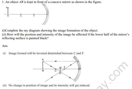
Question 1. An object AB is kept in front of a concave mirror as shown in the figure.
(i) Complete the ray diagram showing the image formation of the object.
(ii) How will the position and intensity of the image be affected if the lower half of the mirror's reflecting surface is painted black?
Answer:
(i) As shown in the completed ray diagram below, the real image is formed in an inverted and diminished state, positioned between the focal point \( F \) and the center of curvature \( C \):
(ii) If the lower half of the mirror's reflecting surface is blackened, the overall position of the image remains completely unchanged. However, because only half of the reflecting area is available to bounce the light rays, the brightness or intensity of the resulting image will be halved.
In simple words: The position of the image does not change even if part of the mirror is covered, but the image becomes dimmer because less light is reflected.
Exam Tip: Remember that covering or painting a portion of a lens or mirror never changes the image's location or completeness - it only decreases its brightness because fewer light rays contribute to its formation.
Question 2. How does focal length of a lens change when red light incident on it is replaced by violet light? Give reason for your answer.
Answer:
According to the Lens Maker's Formula: \[ \frac{1}{f} = (\mu - 1) \left( \frac{1}{R_1} - \frac{1}{R_2} \right) \] This shows that the focal length of a lens is inversely proportional to its refractive index minus one: \[ f \propto \frac{1}{\mu - 1} \] Since the refractive index of glass for violet light is greater than that for red light (\( \mu_V > \mu_R \)), the lens bends violet light more sharply than red light. Consequently, replacing red light with violet light leads to a reduction in the focal length of the lens.
In simple words: Violet light bends more than red light because glass has a higher refractive index for violet. This extra bending brings the focus closer, decreasing the focal length.
Exam Tip: Use Cauchy's formula \( \mu = A + \frac{B}{\lambda^2} \) to show that refractive index increases as wavelength decreases, which directly connects violet's shorter wavelength to its smaller focal length.
Question 3. Define power of a lens. Write its units. Deduce the relation 1/f = 1/f1 +1/f 2 =+ for two thin lenses kept in contact coaxially.
Answer:
Power of a lens measures its ability to converge or diverge light rays. Mathematically, it is the reciprocal of the focal length of the lens (measured in meters): \[ P = \frac{1}{f\text{ (in meters)}} \] The SI unit of lens power is Diopter (\text{D}).
Derivation:
Consider two thin lenses, \( A \) and \( B \), with focal lengths \( f_1 \) and \( f_2 \), respectively, placed coaxially in contact.
An object is positioned at a point \( O \) on the principal axis. The first lens \( A \) alone would form an image at \( I_1 \), which serves as a virtual object for the second lens \( B \). The second lens then produces the final image at \( I \).
Applying the thin lens formula for lens \( A \) (assuming image distance is \( v_1 \) and object distance is \( u \)): \[ \frac{1}{v_1} - \frac{1}{u} = \frac{1}{f_1} \quad \text{---(i)} \] For lens \( B \), treating \( I_1 \) as a virtual object (at distance \( v_1 \)) and forming the final image at \( v \): \[ \frac{1}{v} - \frac{1}{v_1} = \frac{1}{f_2} \quad \text{---(ii)} \] Adding equations (i) and (ii): \[ \left(\frac{1}{v_1} - \frac{1}{u}\right) + \left(\frac{1}{v} - \frac{1}{v_1}\right) = \frac{1}{f_1} + \frac{1}{f_2} \] \[ \frac{1}{v} - \frac{1}{u} = \frac{1}{f_1} + \frac{1}{f_2} \quad \text{---(iii)} \] If this combination is replaced by a single equivalent lens of focal length \( f \), we have: \[ \frac{1}{v} - \frac{1}{u} = \frac{1}{f} \quad \text{---(iv)} \] Comparing equations (iii) and (iv): \[ \frac{1}{f} = \frac{1}{f_1} + \frac{1}{f_2} \]
In simple words: The power of a lens is how strongly it bends light, which is 1 divided by its focal length in meters. When you put two lenses together, their combined focal power is just the sum of their individual powers.
Exam Tip: When deriving this, clearly state the assumption that the lenses are extremely thin so that the optical centers can be assumed to be at the same point.
Question 4. A convex lens of focal length 25 cm is placed coaxially in contact with a concave lens of focal length 20 cm. Determine the power of the combination. Will the system be converging or diverging in nature?
Answer:
Given:
• Focal length of the convex lens, \( f_1 = +25\text{ cm} = +0.25\text{ m} \)
• Focal length of the concave lens, \( f_2 = -20\text{ cm} = -0.20\text{ m} \)
The power of the convex lens (\( P_1 \)) is: \[ P_1 = \frac{100}{f_1\text{ (in cm)}} = \frac{100}{+25} = +4\text{ D} \] The power of the concave lens (\( P_2 \)) is: \[ P_2 = \frac{100}{f_2\text{ (in cm)}} = \frac{100}{-20} = -5\text{ D} \] The total power of the combination (\( P \)) is: \[ P = P_1 + P_2 = +4\text{ D} + (-5\text{ D}) = -1\text{ D} \] Since the combined power of the lens system is negative, the combination acts as a diverging system (like a concave lens).
In simple words: The convex lens has a power of +4 D, and the concave lens has a power of -5 D. Together, they have a power of -1 D, meaning the system behaves like a net diverging lens.
Exam Tip: Always use proper sign conventions for focal length (positive for convex, negative for concave) before adding their powers.
Question 6. A thin convex lens having two surfaces of radii of curvature R1 and R2 is made of a material of refractive index \(\mu_2\). It is kept in a medium of refractive index \(\mu_1\). Derive, with the help of a ray diagram, the lens maker formula when a point object placed on the principal axis in front of the radius of curvature R1 produces an image I on the other side of the lens.
Answer:
Consider a thin convex lens of refractive index \( \mu_2 \) placed in a surrounding medium of refractive index \( \mu_1 \). Let \( R_1 \) and \( R_2 \) be the radii of curvature of the two spherical surfaces \( ABC \) and \( ADC \), respectively. A point object \( O \) is placed on the principal axis in the medium of refractive index \( \mu_1 \). A ray of light from \( O \) incident on the first surface \( ABC \) undergoes refraction from medium 1 to medium 2. If the second surface were absent, this surface would form a real image at \( I_1 \). Applying the refraction formula at a spherical interface for the first surface \( ABC \): \[ \frac{\mu_2}{v_1} - \frac{\mu_1}{OB} = \frac{\mu_2 - \mu_1}{BC_1} \quad \text{---(1)} \] Since the lens is thin, we can approximate the distances from the poles \( B \) and \( D \) to be measured from the center, so \( OB \approx u \), \( DI_1 \approx v_1 \), and \( BC_1 = R_1 \). For refraction at the second surface \( ADC \), the light ray travels from medium 2 back into medium 1. The image \( I_1 \) acts as a virtual object for this surface, forming the final image at \( I \). Applying the refraction formula for the second interface (with object distance \( v_1 \) and final image distance \( v \)): \[ \frac{\mu_1}{v} - \frac{\mu_2}{v_1} = \frac{\mu_1 - \mu_2}{DC_2} \quad \text{---(2)} \] Adding equations (1) and (2): \[ \left( \frac{\mu_2}{v_1} - \frac{\mu_1}{u} \right) + \left( \frac{\mu_1}{v} - \frac{\mu_2}{v_1} \right) = \frac{\mu_2 - \mu_1}{R_1} + \frac{\mu_1 - \mu_2}{R_2} \] Simplifying this yields: \[ \mu_1 \left( \frac{1}{v} - \frac{1}{u} \right) = (\mu_2 - \mu_1) \left( \frac{1}{R_1} - \frac{1}{R_2} \right) \] Dividing both sides by \( \mu_1 \): \[ \frac{1}{v} - \frac{1}{u} = \left( \frac{\mu_2}{\mu_1} - 1 \right) \left( \frac{1}{R_1} - \frac{1}{R_2} \right) \] If the object is at infinity (\( u = \infty \)), the image is formed at the focal point (\( v = f \line \)): \[ \frac{1}{f} = \left( \frac{\mu_2}{\mu_1} - 1 \right) \left( \frac{1}{R_1} - \frac{1}{R_2} \right) \] Using sign conventions where \( BC_1 = +R_1 \) and \( DC_2 = -R_2 \): \[ \frac{1}{f} = (\mu_{21} - 1) \left( \frac{1}{R_1} - \frac{1}{R_2} \right) \] where \( \mu_{21} = \frac{\mu_2}{\mu_1} \) is the relative refractive index of the lens material with respect to the medium.
In simple words: The lens maker's formula calculates the focal length based on how much the lens material bends light (its refractive index) and the curvature of both of its surfaces.
Exam Tip: Do not forget to state that \( I_1 \) acts as a virtual object for the second refracting surface; this is a critical conceptual step that examiners specifically check for.
Question 8. A biconvex lens made of a transparent material of refractive index 1.25 is immersed in water of refractive index 1.33. Will the lens behave as a converging lens? Give reason.
Answer:
Given:
• Refractive index of the lens, \( \mu_g = 1.25 \)
• Refractive index of the medium (water), \( \mu_w = 1.33 \)
Since the refractive index of the lens material is less than that of the surrounding medium (\( \mu_g < \mu_w \)), the relative refractive index \( \mu_{21} = \frac{\mu_g}{\mu_w} = \frac{1.25}{1.33} < 1 \). According to the Lens Maker's Formula: \[ \frac{1}{f} = (\mu_{21} - 1) \left( \frac{1}{R_1} - \frac{1}{R_2} \right) \] For a biconvex lens, \( \left( \frac{1}{R_1} - \frac{1}{R_2} \right) \) is positive. However, since \( \mu_{21} - 1 < 0 \), the focal length \( f \) becomes negative. Consequently, the biconvex lens (which is normally converging in air) will behave as a diverging lens when immersed in water.
In simple words: Since water bends light more than the lens material, the light rays diverge instead of converging. The lens swaps its behavior and acts like a diverging lens.
Exam Tip: When a lens is placed in a medium with a higher refractive index than its own, its nature always reverses (converging becomes diverging, and vice-versa).
Question 10. A converging lens of refractive index 1.5 is kept in a liquid medium having same refractive index. What would be the focal length of the lens in this medium?
Draw a plot showing the variation of power of a lens with the wavelength of the incident light. A diverging lens of refractive index 1.5 and of focal length 20 cm in air has the same radii of curvature for both sides. If it is immersed in a liquid of refractive index 1.7, calculate the focal length of the lens in the liquid.
Answer:
1. Lens in medium of same refractive index:
Given: \( \mu_l = \mu_g = 1.5 \). The relative refractive index is \( \mu_{21} = \frac{\mu_g}{\mu_l} = 1 \). Applying Lens Maker's Formula: \[ \frac{1}{f_l} = (\mu_{21} - 1) \left( \frac{1}{R_1} - \frac{1}{R_2} \right) = (1 - 1) \left( \frac{1}{R_1} - \frac{1}{R_2} \right) = 0 \] \[ f_l = \infty \] Thus, the focal length of the lens becomes infinite, and it behaves like a simple flat glass sheet.
2. Plot showing variation of power with wavelength:
Since the refractive index \( n \) decreases with an increase in wavelength (\( \lambda \)) according to Cauchy's relation: \[ n \approx A + \frac{B}{\lambda^2} \] Since power is \( P = \frac{1}{f} = (n - 1)\left(\frac{1}{R_1} - \frac{1}{R_2}\right) \), the power of the lens is proportional to \( (n - 1) \). Thus, power \( P \) decreases as the wavelength \( \lambda \) increases: \[ P \propto \frac{1}{\lambda^2} \text{ (approximately)} \]
3. Diverging lens in liquid:
Given:
• Refractive index of lens in air, \( \mu_g = 1.5 \)
• Focal length in air, \( f_a = -20\text{ cm} \) (since it is a diverging lens)
• Refractive index of liquid, \( \mu_l = 1.7 \)
The formula relating focal length in a liquid (\( f_l \)) to focal length in air (\( f_a \)) is: \[ f_l = \frac{\mu_g - 1}{\frac{\mu_g}{\mu_l} - 1} \times f_a \] Substitute the values: \[ f_l = \frac{1.5 - 1}{\frac{1.5}{1.7} - 1} \times (-20\text{ cm}) \] \[ f_l = \frac{0.5}{\frac{1.5 - 1.7}{1.7}} \times (-20) \] \[ f_l = \frac{0.5 \times 1.7}{-0.2} \times (-20) \] \[ f_l = \frac{0.85}{-0.2} \times (-20) = -4.25 \times (-20) = +85\text{ cm} \]
In simple words: When a lens is kept in a liquid of the same refractive index, light doesn't bend at all, so its focal length becomes infinite. Also, since longer wavelengths bend less, lens power decreases as wavelength increases. For the diverging lens in a denser liquid, its focal length changes to +85 cm, meaning it now behaves like a converging lens.
Exam Tip: Pay careful attention to the sign of \( f_a \) (negative for a diverging lens). Since the liquid is optically denser than the lens material, the focal length changes sign from negative to positive.
Question 12. With the help of a suitable ray diagram, derive the mirror formula for a concave mirror.
Answer:
Consider a concave mirror \( M_1M_2 \) with pole \( P \), focus \( F \), and center of curvature \( C \). An object \( AB \) is placed on the principal axis beyond the center of curvature \( C \). A real, inverted, and diminished image \( A'B' \) is formed between \( C \) and \( F \). Draw a perpendicular \( DN \) from the point of incidence \( D \) to the principal axis. In similar triangles \( \Delta ABC \) and \( \Delta A'B'C \): \[ \frac{AB}{A'B'} = \frac{BC}{B'C} \quad \text{---(1)} \] Similarly, in similar triangles \( \Delta DNF \) and \( \Delta A'B'F \): \[ \frac{DN}{A'B'} = \frac{NF}{B'F} \] Since \( DN = AB \) (as \( AD \) is parallel to the principal axis): \[ \frac{AB}{A'B'} = \frac{NF}{B'F} \quad \text{---(2)} \] Comparing equations (1) and (2): \[ \frac{BC}{B'C} = \frac{NF}{B'F} \] If the aperture of the mirror is very small, the point \( N \) lies very close to \( P \line \), so we can approximate \( NF \approx PF \): \[ \frac{BC}{B'C} = \frac{PF}{B'F} \] Using the sign conventions:
• Object distance, \( PB = -u \)
• Image distance, \( PB' = -v \)
• Focal length, \( PF = -f \)
• Radius of curvature, \( PC = -R = -2f \)
Expressing the distances in terms of distances from the pole \( P \): \[ BC = PB - PC = -u - (-2f) = -u + 2f \] \[ B'C = PC - PB' = -2f - (-v) = -2f + v \] \[ B'F = PB' - PF = -v - (-f) = -v + f \] Substituting these into the relation: \[ \frac{-u + 2f}{-2f + v} = \frac{-f}{-v + f} \] \[ (-u + 2f)(-v + f) = -f(-2f + v) \] \[ uv - uf - 2vf + 2f^2 = 2f^2 - vf \] \[ uv - uf - vf = 0 \] \[ uv = uf + vf \] Dividing both sides by \( uvf \): \[ \frac{1}{f} = \frac{1}{v} + \frac{1}{u} \]
In simple words: The mirror formula relates the object distance, image distance, and focal length using geometry. By using similar triangles formed by the light rays, we get the equation \( \frac{1}{v} + \frac{1}{u} = \frac{1}{f} \).
Exam Tip: When deriving this, always draw the perpendicular \( DN \) and state the small-aperture assumption clearly. Applying Cartesian sign conventions correctly is vital for getting full marks.
Question 1. (i) A ray of monochromatic light is incident on one of the faces of an equilateral triangular prismof refracting angle A. Trace the path of ray passing through the prism. Hence, derive anexpression for the refractive index of the material of the prism in terms of the angle minimumdeviation and its refracting angle.
(ii) Three light rays red (R), green (G) and blue (B) areincident on the right angled prism abc at face ab. The refractive indices of the material of the prism for red,green and blue wavelengths are respectively 1.39, 1.44 and 1.47. Trace the paths of these rays reasoning outthe difference in their behaviour.
Answer:
Part (i): Prism Formula Derivation
Let \( PQR \) be the principal section of a triangular prism with a refracting angle \( A \). A monochromatic ray of light \( EF \) is incident on face \( PQ \) at an angle \( i_1 \). Since it enters a denser medium (glass), it bends towards the normal \( N_1 \), traveling along \( FG \) with an angle of refraction \( r_1 \). This ray then hits the second face \( PR \) at an angle \( r_2 \) and emerges into the air along \( GH \) at an angle of emergence \( i_2 \), bending away from the normal \( N_2 \). The angle between the direction of the incident ray \( EF \) (produced forward) and the emergent ray \( GH \) (produced backward) is the angle of deviation \( \delta \). From geometry: In \( \Delta FOG \), the exterior angle is the angle of deviation: \[ \delta = \angle OFG + \angle OGF = (i_1 - r_1) + (i_2 - r_2) \] \[ \delta = (i_1 + i_2) - (r_1 + r_2) \quad \text{---(i)} \] In the quadrilateral \( FNGP \), the angles at \( F \) and \( G \) are right angles, so: \[ A + \angle FNG = 180^\circ \quad \text{---(ii)} \] In \( \Delta FNG \): \[ r_1 + r_2 + \angle FNG = 180^\circ \quad \text{---(iii)} \] Comparing (ii) and (iii): \[ r_1 + r_2 = A \quad \text{---(iv)} \] Substitute this into equation (i): \[ \delta = i_1 + i_2 - A \quad \text{---(v)} \] Under the condition of minimum deviation (\( \delta = \delta_m \)), the ray passes symmetrically through the prism, meaning: \[ i_1 = i_2 = i \quad \text{and} \quad r_1 = r_2 = r \] From equation (iv): \[ 2r = A \implies r = \frac{A}{2} \] From equation (v): \[ \delta_m = 2i - A \implies i = \frac{A + \delta_m}{2} \] According to Snell's law, the refractive index \( n \) of the prism material is: \[ n = \frac{\sin i}{\sin r} = \frac{\sin \left( \frac{A + \delta_m}{2} \right)}{\sin \left( \frac{A}{2} \right)} \]
Part (ii): Three rays on a right-angled prism
The angle of incidence at face \( AC \) for all three colors is \( i = 45^\circ \). The critical angle \( \theta_c \) for any color is given by: \[ \sin \theta_c = \frac{1}{\mu} \implies \mu = \frac{1}{\sin 45^\circ} = \sqrt{2} \approx 1.414 \]
• If the refractive index of a color is greater than \( 1.414 \) (\( \mu > 1.414 \)), it will undergo Total Internal Reflection (TIR).
• If the refractive index is less than \( 1.414 \) (\( \mu < 1.414 \)), it will refract out of the prism.
Given:
• Red (\( \mu = 1.39 < 1.414 \)): Refracts out of face \( AC \).
• Green (\( \mu = 1.44 > 1.414 \Line \)): Undergoes TIR at face \( AC \).
• Blue (\( \mu = 1.47 > 1.414 \)): Undergoes TIR at face \( AC \).
Therefore, only the red ray emerges from the other side, while green and blue rays are reflected internally.
In simple words: Part (i) uses geometry to find the prism formula \( n = \frac{\sin[(A+\delta_m)/2]}{\sin(A/2)} \). Part (ii) shows that colors with a refractive index higher than 1.414 (green and blue) hit the glass-air boundary at an angle larger than their critical angle, causing them to reflect inward. Red, having a lower index, passes through.
Exam Tip: For TIR questions, always calculate the threshold value of refractive index (\( \mu = \frac{1}{\sin i} \)) first, then compare each given index to clearly justify which rays reflect and which refract.
Question Q2. A ray of light, incident on an equilateral glass prism (\(\mu_g = \sqrt{3}\)) moves parallel to the base line of the prism inside it. Find the angle of incidence for this ray.
Answer:
Since the ray inside the prism travels parallel to the base, it undergoes refraction symmetrically. Thus: \[ r_1 = r_2 = r \] For an equilateral prism, the angle of the prism is \( A = 60^\circ \). We know: \[ r_1 + r_2 = A \implies 2r = 60^\circ \implies r = 30^\circ \] According to Snell's law: \[ n = \frac{\sin i}{\sin r} \] Substitute the given values: \[ \sqrt{3} = \frac{\sin i}{\sin 30^\circ} \] \[ \sin i = \sqrt{3} \times \sin 30^\circ = \sqrt{3} \times \frac{1}{2} = \frac{\sqrt{3}}{2} \] Since \( \sin 60^\circ = \frac{\sqrt{3}}{2} \): \[ i = 60^\circ \]
In simple words: Because the light travels parallel to the bottom of the equilateral prism, the angle of refraction is exactly half of the prism's 60-degree angle, which is 30 degrees. Using Snell's law with a refractive index of \( \sqrt{3} \), we find the angle of incidence is 60 degrees.
Exam Tip: The phrase "moves parallel to the base line" is a direct trigger indicating symmetric refraction under the condition of minimum deviation where \( r = A/2 \).
Question 3. Define magnifying power of a telescope. Write its expression.
Answer:
The magnifying power of a telescope is defined as the ratio of the angle subtended at the eye by the final image to the angle subtended at the unaided eye by the object (when both are at infinity). \[ m = \frac{\beta}{\alpha} \]
• For Normal Adjustment (comfortable view, image at infinity): \[ m = -\frac{f_o}{f_e} \]
• For Near Point Focus (strained eye, image at least distance of distinct vision \( D \)): \[ m = -\frac{f_o}{f_e} \left( 1 + \frac{f_e}{D} \right) \] where \( f_o \) is the focal length of the objective lens and \( f_e \) is the focal length of the eyepiece.
In simple words: Magnifying power compares how big an object looks through the telescope versus looking at it with just your eyes.
Exam Tip: State both formulas (image at infinity and image at near point) and clearly define all variables to secure maximum marks.
Question 4. (a) How is the working of a telescope different from that of a microscope?
(b) The focal lengths of the objective and eyepiece of a microscope are 1.25 cm and 5 cmrespectively. Find the position of the object relative to the objective in order to obtain an angularmagnification of 30 in normal adjustment.
Answer:
(a) Differences in Working:
• A telescope is designed to view highly distant objects (like stars or planets), so its objective lens forms a real image of the distant object at or near its focus. A microscope is used to view very small, nearby objects, with the object placed just beyond the focus of the objective lens.
• For a telescope, the objective lens has a large focal length and a wide aperture to gather maximum light. In contrast, a microscope's objective has a very short focal length and a small aperture.
(b) Calculation:
Given:
• Focal length of objective lens, \( f_o = 1.25\text{ cm} \)
• Focal length of eyepiece, \( f_e = 5\text{ cm} \)
• Total magnification in normal adjustment, \( m = -30 \) (the negative sign indicates an inverted final image)
In normal adjustment, the magnification of the eyepiece (\( m_e \)) is: \[ m_e = \frac{D}{f_e} = \frac{25}{5} = 5 \] Since total magnification is \( m = m_o \times m_e \): \[ -30 = m_o \times 5 \implies m_o = -6 \] Using the formula for the linear magnification of the objective lens: \[ m_o = \frac{v_o}{u_o} \implies -6 = \frac{v_o}{u_o} \implies v_o = -6u_o \] Applying the lens formula to the objective lens: \[ \frac{1}{f_o} = \frac{1}{v_o} - \frac{1}{u_o} \] \[ \frac{1}{1.25} = \frac{1}{-6u_o} - \frac{1}{u_o} \] \[ \frac{1}{1.25} = \frac{-1 - 6}{6u_o} = \frac{-7}{6u_o} \] \[ 6u_o = -7 \times 1.25 \implies u_o = \frac{-8.75}{6} \approx -1.46\text{ cm} \] Therefore, the object should be placed at a distance of \( 1.46\text{ cm} \) in front of the objective lens.
In simple words: Part (a) explains that telescopes look at large, far-away things using big lenses, while microscopes look at tiny, close-up things using small lenses. Part (b) calculates that to get a 30x zoom, the object must be placed 1.46 cm away from the first microscope lens.
Exam Tip: Always remember that "normal adjustment" for a microscope means the final image is formed at the near point (\( D = 25\text{ cm} \)), which determines the eyepiece magnification formula \( m_e = \frac{D}{f_e} \).
Question 5. Draw a labelled ray diagram of a reflecting telescope. Mention its two advantages over therefracting telescope.
Answer:
Ray Diagram of Reflecting (Cassegrain) Telescope:
Advantages over Refracting Telescope:
• No Chromatic Aberration: Since mirrors reflect light rather than refracting it, reflecting telescopes are completely free of chromatic aberration (color distortion).
• High Resolving Power and Easier Support: Parabolic mirrors can easily be made with much wider apertures to collect more light, and since the mirror can be physically supported from its entire back surface, it is much easier to construct mechanically than a heavy glass lens.
In simple words: Reflecting telescopes use a curved mirror to collect light instead of a lens. This prevents color fringing (chromatic aberration) and allows us to build much larger telescopes.
Exam Tip: Always draw Cassegrain telescopes with a hole in the center of the primary mirror where the light exits to the eyepiece.
Question 7. Draw a ray diagram showing the image formation by a compound microscope. Hence obtainexpression for total magnification when the image is formed at infinity.
Answer:
For a compound microscope to form its final image at infinity, the intermediate real image \( A'B' \) formed by the objective lens must lie precisely at the principal focal point \( F_e \) of the eyepiece.
• Magnification by Objective Lens (\( m_o \)): \[ m_o = \frac{L}{f_o} \] where \( L \) represents the tube length (distance between the focus of the objective and the focus of the eyepiece) and \( f_o \) is the focal length of the objective lens.
• Magnification by Eyepiece (\( m_e \)): Since the final image is at infinity, the eyepiece acts as a simple magnifier with the object at its focus: \[ m_e = \frac{D}{f_e} \] where \( D \) is the least distance of distinct vision and \( f_e \) is the focal length of the eyepiece.
• Total Magnification (\( m \)): The total magnifying power is the product of both individual magnifications: \[ m = m_o \times m_e = -\left( \frac{L}{f_o} \right) \left( \frac{D}{f_e} \right) \]
In simple words: To see a relaxed image at infinity through a microscope, the first lens must place the intermediate image exactly at the focus of the second lens. The total magnification is the product of both lenses' individual magnifications.
Exam Tip: The formula with a negative sign indicates that the final image is inverted with respect to the original object. Make sure to define \( L \) as the tube length clearly.
Question 8. Draw a labelled ray diagram of a refracting telescope. Define its magnifying power and write the expression for it.
Write two important limitations of a refracting telescope over a reflecting type telescope.
Answer:
Ray Diagram of Refracting Telescope:
Magnifying Power Definition and Expression:
Magnifying power is the ratio of the angle subtended by the final image at the eye (\( \beta \)) to the angle subtended by the object at the lens (\( \alpha \)): \[ m = \frac{\beta}{\alpha} \]
• For comfortable normal view: \( m = -\frac{f_o}{f_e} \)
• For strained distinct vision view: \( m = -\frac{f_o}{f_e}\left(1 + \frac{f_e}{D}\right) \)
Limitations of Refracting Telescope:
• Chromatic Aberration: Glass lenses disperse light of different colors at different focal points, producing colored fringes around the image.
• Spherical Aberration: Heavy lenses with spherical surfaces fail to bring all rays to a single point focus, resulting in a slightly blurred image.
In simple words: Refracting telescopes use lenses to focus light, which leads to color blur (chromatic aberration) and distortion due to lens weight. Reflecting telescopes bypass these problems entirely.
Exam Tip: Always state the two aberrations (chromatic and spherical) as the primary limitations of refracting lenses when compared to mirrors.
Question 9. Three rays of light, red (R), green (G) and blue (B), are incident on the face AB of a right angledprism, as shown in the figure. The refractive indices of the material of the prism for red, green andblue are 1.39, 1.44 and 1.47 respectively. Which one of the three rays will emerge out of the prism?Give reason to support your answer.
Answer:
At the glass-air boundary (face \( AC \)), the angle of incidence for all three colored rays is \( i = 45^\circ \). The critical angle \( i_c \) for the boundary is defined by: \[ \sin i_c = \frac{1}{\mu} \implies \mu_c = \frac{1}{\sin 45^\circ} = \sqrt{2} \approx 1.414 \]
• If the refractive index of a ray's color is greater than \( 1.414 \), it undergoes Total Internal Reflection (TIR) and does not emerge.
• If the refractive index is less than \( 1.414 \), the ray refracts through the face and emerges.
Analyzing the given colors:
• Red: \( \mu_R = 1.39 < 1.414 \) (emerges through face \( AC \))
• Green: \( \mu_G = 1.44 > 1.414 \) (undergoes total internal reflection)
• Blue: \( \mu_B = 1.47 > 1.414 \) (undergoes total internal reflection)
Thus, only the red ray will emerge from the prism face \( AC \).
In simple words: Since green and blue light bend more in glass, they hit the boundary at an angle greater than their critical angle, reflecting back inside. Red light bends less, so it escapes.
Exam Tip: Show the calculation for the threshold index (\( \mu = 1.414 \)) explicitly, as it makes your argument mathematically solid.
Question 10. (i) Draw a schematic labelled ray diagram of a reflecting type telescope.
(ii) Write two important advantages justifying why reflecting type telescopes are preferred over refracting telescopes.
(iii) The objective of a telescope is of larger focal length and of larger aperture (compared to the eyepiece). Why? Give reasons.
Answer:
(i) Ray Diagram:
Refer to the schematic Cassegrain reflecting telescope diagram provided in Question 5 above.
(ii) Advantages:
• No Chromatic Aberration: Since mirrors are used instead of lenses, color dispersion is completely avoided.
• Parabolic Mirror Advantage: Using a parabolic mirror eliminates spherical aberration entirely.
(iii) Large Focal Length and Aperture of Objective:
• Larger Aperture: A wider objective gathers a massive amount of light from distant, faint celestial sources, which increases both the brightness and resolving power (\( \text{RP} \propto \text{aperture} \)) of the image.
• Larger Focal Length: Since the magnifying power is \( m = -\frac{f_o}{f_e} \), increasing the objective's focal length (\( f_o \)) directly boosts the telescope's magnification.
In simple words: (i) Mirrors reflect all colors equally, so we get crisp, clear pictures without color fringes. (ii) A larger front lens/mirror is needed to catch more light from faint stars, and a longer length makes the zoom stronger.
Exam Tip: Clearly link large aperture to resolving power (\( \frac{D}{1.22 \lambda} \)) and large focal length to magnifying power (\( \frac{f_o}{f_e} \)) to show a complete, rigorous understanding.
Question 11. (a) Draw a labelled ray diagram of a compound microscope.
(b) Derive an expression for its magnifying power.
(c) Why is objective of a microscope of short aperture and short focal length? Give reason.
Answer:
(a) Labelled Ray Diagram:
(b) Magnifying Power Derivation:
Total magnification \( m \) is given by the product of the magnifications of the objective (\( m_o \)) and eyepiece (\( m_e \)): \[ m = m_o \times m_e \] For a small object, objective magnification is: \[ m_o = \frac{v_o}{u_o} \approx -\frac{L}{f_o} \] If the final image is formed at the near point (\( D \)): \[ m_e = 1 + \frac{D}{f_e} \] Thus, total magnification is: \[ m = -\frac{L}{f_o} \left( 1 + \frac{D}{f_e} \right) \] If the final image is formed at infinity: \[ m_e = \frac{D}{f_e} \implies m = -\frac{L}{f_o} \times \frac{D}{f_e} \]
(c) Reason for Small Aperture and Short Focal Length:
A small focal length \( f_o \) and aperture are preferred for the objective lens because magnifying power is inversely proportional to \( f_o \) (\( m \propto \frac{1}{f_o} \)). Thus, a smaller focal length yields a much higher zoom. A smaller aperture also concentrates the light rays collected from close-up objects, improving clarity and brightness.
In simple words: (a) A compound microscope uses two lenses: a tiny objective lens to make a small real image, and a larger eyepiece lens to magnify it further. (b) The magnification is the product of both lenses. (c) The objective has a tiny focal length because smaller focal lengths produce much higher magnifying power.
Exam Tip: Clearly distinguish between the two final image conditions (at near point vs at infinity) as their eyepiece magnification expressions are different.
Wave Optics & Huygen's Principle
Question 1. How is a wavefront defined ? Using Huygen’s construction draw a figure showing the propagation of a plane wave refracting at a plane surface separating two media. Hence verify Snell’s law of refraction.
Answer:
Definition of Wavefront:
A wavefront is defined as the locus of all neighboring points or particles of a medium that are vibrating in the same phase of oscillation at any given instant.
Verification of Snell's Law:
Consider a plane wavefront \( AB \) incident obliquely on a plane boundary surface \( XY \) separating two transparent media of refractive indices \( n_1 \) and \( n_2 \), where the wave velocities are \( v_1 \) and \( v_2 \), respectively.
Let the wavefront touch the boundary at point \( A \) at time \( t = 0 \). The other end \( B \) travels a distance \( BB' = v_1 t \) in medium 1 to reach point \( B' \) on the boundary at time \( t \).
According to Huygen's principle, every point on the boundary becomes a source of secondary wavelets. The secondary wavelet starting from \( A \) travels into medium 2 with velocity \( v_2 \) and covers a distance \( AA' = v_2 t \) in time \( t \).
To find the new refracted wavefront, we draw a spherical arc of radius \( AA' = v_2 t \) centered at \( A \) and draw a tangent plane \( A'B' \) from \( B' \) to this arc. This tangent plane \( A'B' \) represents the refracted plane wavefront.
From the right-angled triangles \( \Delta AB'B \) and \( \Delta AB'A' \):
In \( \Delta AB'B \): \[ \sin i = \frac{BB'}{AB'} = \frac{v_1 t}{AB'} \quad \text{---(1)} \] In \( \Delta AB'A' \): \[ \sin r = \frac{AA'}{AB'} = \frac{v_2 t}{AB'} \quad \text{---(2)} \] Dividing equation (1) by (2): \[ \frac{\sin i}{\sin r} = \frac{v_1 t / AB'}{v_2 t / AB'} = \frac{v_1}{v_2} = \text{constant} \] Since the ratio of wave speeds is equal to the relative refractive index of medium 2 with respect to medium 1: \[ \frac{\sin i}{\sin r} = \frac{n_2}{n_1} = \text{constant} \] This verifies Snell's law of refraction.
In simple words: A wavefront is a line or surface where all parts of a light wave are at the exact same point in their wave cycle (vibrating in sync). By comparing the distance light travels in two different materials over the same time, we mathematically derive Snell's law (\( \frac{\sin i}{\sin r} = \text{constant} \)).
Exam Tip: Draw the triangles clearly and show the right angles (\( \angle ABB' = 90^\circ \) and \( \angle AA'B' = 90^\circ \)) to get full marks on the geometric proof.
Question 2. How is a wavefront defined ? Using Huygen’s construction draw a figure showing the Propagation of a plane wave reflecting at the interface of the two media. Show that the angle of incidence is equal to the angle of reflection.
Answer:
Definition of Wavefront:
A wavefront is the locus of all points in a medium vibrating in the same phase at a particular instant.
Proof of Law of Reflection:
Let \( XY \) be a plane reflecting surface. A plane wavefront \( AB \) is incident obliquely on this surface, touching it at point \( A \) at time \( t = 0 \).
The other end \( B \) of the wavefront takes a time \( t \) to reach point \( B' \) on the reflecting surface: \[ BB' = vt \] During this time interval \( t \), the secondary wavelet starting from \( A \) spreads out as a hemisphere in the same medium with speed \( v \), covering a distance \( AA' = vt \).
To locate the reflected wavefront, we draw a spherical arc of radius \( AA' = vt \) centered at \( A \) and draw a tangent line \( A'B' \) from \( B' \). The surface \( A'B' \) represents the reflected plane wavefront.
Now, comparing the right-angled triangles \( \Delta ABB' \) and \( \Delta A'B'A \):
1. \( \angle ABB' = \angle AA'B' = 90^\circ \) (since rays are perpendicular to wavefronts)
2. Hypotenuse \( AB' = AB' \) (common side)
3. Side \( BB' = AA' = vt \)
By RHS congruence: \[ \Delta ABB' \cong \Delta A'B'A \] Therefore, the corresponding angles must be equal: \[ \angle BAB' = \angle A'B'A \] Since \( \angle BAB' \) is the angle of incidence \( i \) and \( \angle A'B'A \) is the angle of reflection \( r \): \[ i = r \] This proves that the angle of incidence is equal to the angle of reflection.
In simple words: By showing that the triangles for the incoming and outgoing wavefronts are congruent (identical in shape and size), we prove that the angle at which the light hits the mirror is exactly equal to the angle at which it bounces off.
Exam Tip: Make sure to state that both triangles share the same hypotenuse (\( AB' \)) and have equal-length sides (\( vt \)) due to constant wave speed in the same medium.
Question 3. Describe Young’s double slit experiment to produce interference pattern due to a monochromatic source of light. Deduce the expression for the fringe width.
Answer:
Description of Young's Double Slit Experiment (YDSE):
In YDSE, light from a monochromatic source passes through a single narrow slit \( S \) and then through two closely spaced parallel slits \( S_1 \) and \( S_2 \). Since \( S_1 \) and \( S_2 \) are derived from the same wavefront, they behave as coherent light sources, producing a stable interference pattern of alternating bright and dark bands (fringes) on a screen placed at a distance \( D \).
Derivation of Fringe Width (\( \beta \)):
Let \( d \) be the separation between slits \( S_1 \) and \( S_2 \), and \( D \) be the distance of the screen from the slits.
Let \( O \) be the central point on the screen, equidistant from \( S_1 \) and \( S_2 \). Consider a point \( P \) on the screen at a distance \( y \) from \( O \).
The path difference \( \Delta \) between the two waves arriving at \( P \) from \( S_1 \) and \( S_2 \) is: \[ \Delta = S_2P - S_1P \] For \( D \gg d \), the path difference is approximated geometrically as: \[ \Delta \approx d \sin \theta \approx d \tan \theta \] Since \( \tan \theta = \frac{y}{D} \): \[ \Delta = \frac{yd}{D} \]
• Positions of Bright Fringes (Maxima): For constructive interference, the path difference must be an integral multiple of the wavelength (\( \lambda \)): \[ \frac{yd}{D} = n\lambda \implies y_n = \frac{n\lambda D}{d} \quad \text{where } n = 0, 1, 2, 3, \dots \]
• Positions of Dark Fringes (Minima): For destructive interference, the path difference must be an odd multiple of half-wavelengths: \[ \frac{yd}{D} = (2n - 1)\frac{\lambda}{2} \implies y_n' = (2n - 1)\frac{\lambda D}{2d} \quad \text{where } n = 1, 2, 3, \dots \]
• Fringe Width (\( \beta \)): The distance between any two consecutive bright or dark fringes is called the fringe width: \[ \beta = y_{n+1} - y_n = \frac{(n+1)\lambda D}{d} - \frac{n\lambda D}{d} = \frac{\lambda D}{d} \] Since this is independent of \( n \), all bright and dark fringes have the same width.
In simple words: In Young's double slit experiment, light from two tiny slits interferes to form bright and dark lines on a screen. The width of each line (fringe) depends on the light's wavelength, the screen's distance, and the slit separation: \( \beta = \frac{\lambda D}{d} \).
Exam Tip: Make sure to derive the path difference \( \Delta = \frac{yd}{D} \) clearly by showing the small-angle approximation \( \sin \theta \approx \tan \theta \).
Question 5. How does the fringe width of interference fringes change, when the whole apparatus of Young’s experiment is kept in a liquid of refractive index 1.3 ?
Answer:
The fringe width in air is given by: \[ \beta = \frac{\lambda D}{d} \] When the entire apparatus is immersed in a liquid of refractive index \( n = 1.3 \), the speed of light decreases, causing the wavelength of light to shrink to: \[ \lambda' = \frac{\lambda}{n} \] Since fringe width is directly proportional to the wavelength (\( \beta \propto \lambda \)), the new fringe width \( \beta' \) in the liquid becomes: \[ \beta' = \frac{\lambda' D}{d} = \frac{\beta}{n} = \frac{\beta}{1.3} \] Therefore, the fringe width decreases to \( \frac{1}{1.3} \) times (or roughly \( 77\% \)) of its original value in air.
In simple words: In a liquid, light slows down and its wavelength gets shorter. Since shorter wavelengths create narrower bands, the fringe width shrinks to 1/1.3 of its original size.
Exam Tip: Remember that both the wavelength and the fringe width scale down by the factor \( 1/n \) when immersed in a medium of refractive index \( n \).
Question 6. How will the angular separation and visibility of fringes in Young’s double slit experiment changewhen (i) screen is moved away from the plane of the slits, and (ii) width of the source slit isincreased?
Answer:
(i) Screen is moved away (\( D \) increases):
• Angular Separation (\( \theta = \frac{\lambda}{d} \)): The angular separation depends only on the wavelength and slit separation. Since it is independent of \( D \), it remains completely unchanged.
• Visibility: The actual fringe width is \( \beta = \frac{\lambda D}{d} \), so the bands become physically wider. Since they are larger and more spread out, the visibility of the fringes increases.
(ii) Width of the source slit is increased:
As the width of the source slit increases, different parts of the wider source act as independent, incoherent light sources. This causes multiple, slightly shifted interference patterns to overlap on the screen. As a result, the bright and dark bands blur together, making the fringes less sharp, until the interference pattern eventually disappears completely.
In simple words: (i) Moving the screen back makes the stripes wider and easier to see, but doesn't change their angular spacing. (ii) Widening the light source blurs the stripes together because too many overlapping patterns are created at once.
Exam Tip: Mention the condition for interference visibility: \( \frac{s}{d} < \frac{\lambda}{a} \), where \( s \) is source width and \( a \) is source-to-slit distance, to show advanced theoretical depth.
Question 7. How would the angular separation of interference fringes in Young’s double slit experiment change when the distance between the slits and screen is doubled?
Answer: The angular fringe spacing is defined as \( \beta_\theta = \frac{\lambda}{d} \), where \( \lambda \) represents the wavelength and \( d \) is the gap between the two slits. This quantity is entirely independent of the distance \( D \) separating the slits from the screen. Consequently, doubling the slit-to-screen distance will have no effect on the angular separation, leaving it completely unaltered.
In simple words: The angle at which the light bands spread out depends only on the color of the light and how close the two slits are. Doubling the distance to the screen changes the size of the projected image but does not change this angle.
Exam Tip: Always write the formula for angular separation first to show that the distance \( D \) is not a variable in it.
Question 8. In Young’s double slit experiment, monochromatic light of wavelength 630 nm illuminates the pair of slits and produces an interference pattern in which two consecutive bright fringes are separated by 8.1 mm. Another source of monochromatic light produces the interference pattern in which the two consecutive bright fringes are separated by 7.2 mm. Find the wavelength of light from the second source. What is the effect on the interference fringes if the monochromatic source is replaced by a source of white light?
Answer: The fringe width is expressed as \( \beta = \frac{\lambda D}{d} \). For a fixed experimental setup, both \( d \) and \( D \) are constant, meaning the fringe width is directly proportional to the wavelength:
\( \beta \propto \lambda \)
We can set up the ratio between the two states:
\( \frac{\beta_2}{\beta_1} = \frac{\lambda_2}{\lambda_1} \)
Solving for the unknown wavelength \( \lambda_2 \):
\( \lambda_2 = \left(\frac{\beta_2}{\beta_1}\right) \lambda_1 \)
Substituting the given parameters (\( \beta_1 = 8.1\text{ mm} \), \( \beta_2 = 7.2\text{ mm} \), and \( \lambda_1 = 630\text{ nm} \)):
\( \lambda_2 = \left(\frac{7.2\text{ mm}}{8.1\text{ mm}}\right) \times 630\text{ nm} \)
\( \implies \lambda_2 = 560\text{ nm} \)
When the monochromatic source is swapped for white light, a central white fringe forms because all wavelengths interfere constructively at the center. Moving away from the center, the different colors separate out because they have different wavelengths, producing a few symmetric colored bands before fading into a uniform, steady illumination.
In simple words: Since the width of the bands matches the wavelength of the light, we can use a simple ratio to find that the second wavelength is 560 nm. Using white light makes the very center look pure white, surrounded by a few rainbow-colored bands on each side before blending into general light.
Exam Tip: Make sure to keep the units consistent when using ratios. Note that the central fringe is always white because the path difference is zero for all wavelengths.
Question 9. In Young’s double slit experiment, the two slits 0.15 mm apart are illuminated by monochromatic light of wavelength 450 nm. The screen is 1.0 m away from the slits. (a) Find the distance of the second (i) bright fringe, (ii) dark fringe from the central maximum. (b) How will the fringe pattern change if the screen is moved away from the slits?
Answer: Given values:
Slit separation, \( d = 0.15\text{ mm} = 0.15 \times 10^{-3}\text{ m} \)
Wavelength, \( \lambda = 450\text{ nm} = 450 \times 10^{-9}\text{ m} \)
Slit-to-screen distance, \( D = 1.0\text{ m} \)
(a) (i) The position of the \( n \)-th bright fringe from the central maximum is given by:
\( y_n = \frac{n D \lambda}{d} \)
For the second bright fringe (\( n = 2 \)):
\( y_2 = \frac{2 \times 1.0\text{ m} \times 450 \times 10^{-9}\text{ m}}{0.15 \times 10^{-3}\text{ m}} \)
\( \implies y_2 = \frac{900 \times 10^{-9}}{0.15 \times 10^{-3}}\text{ m} \)
\( \implies y_2 = 6 \times 10^{-3}\text{ m} = 6\text{ mm} \)
(ii) The position of the \( n \)-th dark fringe is given by:
\( y'_n = \left(n - \frac{1}{2}\right)\frac{D \lambda}{d} \)
For the second dark fringe (\( n = 2 \)):
\( y'_2 = \left(2 - \frac{1}{2}\right) \frac{1.0\text{ m} \times 450 \times 10^{-9}\text{ m}}{0.15 \times 10^{-3}\text{ m}} \)
\( \implies y'_2 = 1.5 \times 3 \times 10^{-3}\text{ m} \)
\( \implies y'_2 = 4.5 \times 10^{-3}\text{ m} = 4.5\text{ mm} \)
(b) If the screen is shifted further away from the slit plane, the distance \( D \) increases. Since the fringe width is defined as \( \beta = \frac{D\lambda}{d} \), an increase in \( D \) will cause the fringe spacing to widen.
In simple words: The second bright stripe is located 6 mm from the center, and the second dark stripe is at 4.5 mm. Moving the screen further back stretches out the pattern, making the individual stripes wider.
Exam Tip: Double-check that you are using \( \left(n - \frac{1}{2}\right) \) for dark fringes and not \( (2n-1)\frac{\lambda D}{2d} \) unless you adjust the value of \( n \) accordingly. Stick to one standard formula to avoid confusion under exam pressure.
DIFFRACTION
Question 10. (a) Describe briefly how a diffraction pattern is obtained on a screen due to a single narrow slit illuminated by a monochromatic source of light. Hence obtain the conditions for the angular width of secondary maxima and secondary minima.
Answer: When a parallel beam of monochromatic light falls normally on a narrow single slit of width \( a \), light waves bend around the edges of the slit. This bending leads to interference between wavelets originating from different parts of the same wavefront, creating a diffraction pattern on a viewing screen placed behind the slit. The resulting pattern features a highly intense central maximum, surrounded by alternating darker and lighter bands (secondary minima and secondary maxima) whose intensities rapidly decrease on either side.
Let \( AB \) be the slit of width \( a \). Consider a plane wavefront incident on this slit. According to Huygens' principle, every point on the wavefront inside the slit acts as a source of secondary wavelets. Let these wavelets propagate at an angle \( \theta \) with the original direction and focus at a point \( P \) on the screen.
The path difference \( \Delta \) between the rays coming from the extreme edges \( A \) and \( B \) of the slit is:
\( \Delta = BP - AP = BN \)
From the right-angled triangle \( ANB \), where \( \angle ANB = 90^\circ \) and \( \angle BAN = \theta \):
\( \sin\theta = \frac{BN}{AB} \implies BN = AB \sin\theta \)
Since the slit width \( AB = a \):
\( \Delta = a \sin\theta \) [Equation 1]
Condition for Minima:
To find the positions of the secondary minima, let us divide the slit into \( 2n \) equal zones. The path difference between wavelets from corresponding points in any two adjacent zones will be \( \frac{\lambda}{2} \). These wavelets interfere destructively, completely canceling each other's effect at point \( P \).
Thus, the general condition for the formation of minima is:
\( a \sin\theta = n\lambda \) for \( n = 1, 2, 3, \dots \) [Equation 2]
For small angles, \( \sin\theta \approx \theta \), so the angular positions of the minima are:
\( \theta_n = \frac{n\lambda}{a} \)
Condition for Secondary Maxima:
To find the locations of the secondary maxima, we consider directions where the slit can be divided into an odd number of equal parts, such as \( 3, 5, 7, \dots \), which is \( (2n+1) \) parts.
If the path difference between the edges is \( a \sin\theta = \frac{3\lambda}{2} \), we can divide the slit into three equal sections. The wavelets from the first two sections will have a path difference of \( \frac{\lambda}{2} \) and cancel each other out. However, the wavelets from the remaining third section will still contribute to the light intensity at \( P \), creating a weak first secondary maximum.
In general, the condition for secondary maxima is:
\( a \sin\theta = \left(n + \frac{1}{2}\right)\lambda \) for \( n = 1, 2, 3, \dots \) [Equation 3]
For small angles, the angular positions of these secondary maxima are:
\( \theta_n' = \left(n + \frac{1}{2}\right)\frac{\lambda}{a} \)
Angular Width:
The angular width of a secondary maximum is the angular distance between two consecutive minima, which is:
\( \Delta \theta = \theta_{n+1} - \theta_n = \frac{(n+1)\lambda}{a} - \frac{n\lambda}{a} = \frac{\lambda}{a} \)
In simple words: When light passes through a very narrow slit, it bends and interferes with itself. This creates a bright, wide band in the center and alternating faint light and dark bands on the sides.
Exam Tip: Be sure to write the exact equations for both minima \( a \sin\theta = n\lambda \) and secondary maxima \( a \sin\theta = (n + \frac{1}{2})\lambda \). Draw the intensity curve showing how the peak intensity drops sharply for higher-order maxima.
Question 11. (a) In a single slit diffraction experiment, a slit of which ‘d’ is illuminated by red light of wavelength 650 nm. For what value of ‘d’ will:
(i) the first minimum fall at an angle of diffraction of 30°, and
(ii) the first maximum fall at an angle of diffraction of 30°?
(b) Why does the intensity of the secondary maximum become less as compared to the central maximum?
Answer: (a) (i) For the formation of the \( n \)-th minimum in single slit diffraction, the path difference condition is given by:
\( d \sin\theta = n\lambda \)
For the first minimum (\( n = 1 \)) at an angle of \( \theta = 30^\circ \) and wavelength \( \lambda = 650\text{ nm} = 650 \times 10^{-9}\text{ m} \):
\( d = \frac{\lambda}{\sin 30^\circ} \)
\( \implies d = \frac{650 \times 10^{-9}\text{ m}}{0.5} \)
\( \implies d = 1.3 \times 10^{-6}\text{ m} = 1.3\,\mu\text{m} \)
(ii) For the first secondary maximum (\( n = 1 \)), the condition is:
\( d \sin\theta = (2n+1)\frac{\lambda}{2} = \frac{3\lambda}{2} \)
Substituting \( \theta = 30^\circ \) and \( \lambda = 650 \times 10^{-9}\text{ m} \):
\( d = \frac{3\lambda}{2 \sin 30^\circ} \)
\( \implies d = \frac{3 \times 650 \times 10^{-9}\text{ m}}{2 \times 0.5} \)
\( \implies d = 1.95 \times 10^{-6}\text{ m} = 1.95\,\mu\text{m} \)
(b) At the central maximum, secondary wavelets from the entire width of the slit arrive in the same phase and interfere constructively, yielding maximum intensity. For the first secondary maximum, however, the slit can be imagined as split into three equal parts. The wavelets from two of these parts interfere destructively and cancel each other out, leaving only the remaining one-third of the slit to contribute to the intensity. For the second secondary maximum, only one-fifth of the slit contributes. As a result, the intensity of successive secondary maxima drops drastically.
In simple words: For a minimum at 30 degrees, the slit width needs to be 1.3 micrometers, and for a maximum, it needs to be 1.95 micrometers. The side bright bands are much dimmer because only a small fraction of the slit's light (like 1/3rd or 1/5th) actually adds up to make them, while the rest cancels out.
Exam Tip: Remember that for diffraction, the condition for minima uses integer multiples of \( \lambda \), which is opposite to the condition for maxima in double-slit interference. Clearly write down the value of \( \sin 30^\circ = 0.5 \) to show your step-by-step math.
Question 12. (a) Why do we not encounter diffraction effects of light in everyday observations?
(b) In the observed diffraction pattern due to a single slit, how will the width of central maximum be affected if (i) the width of the slit is doubled; (ii) the wavelength of the light used is increased? Justify your answer in each case.
Answer: (a) For diffraction of a wave to be noticeable, the size of the obstacle or slit must be comparable to the wave's wavelength. Since the wavelength of visible light is incredibly tiny (ranging from roughly \( 400\text{ nm} \) to \( 700\text{ nm} \)), and the obstacles or openings we encounter in daily life (like doors or windows) are on the scale of meters, light does not diffract noticeably. Sound waves, on the other hand, have wavelengths in the range of centimeters to meters, which is why we easily hear sound bending around corners but do not see light doing so.
(b) The linear width of the central maximum is expressed by the formula:
\( w = \frac{2\lambda D}{a} \)
where \( \lambda \) is the wavelength, \( D \) is the distance to the screen, and \( a \) is the slit width.
(i) If the slit width \( a \) is doubled, the width of the central maximum is halved because \( w \propto \frac{1}{a} \). Hence, the central maximum becomes narrower and more sharp.
(ii) If the wavelength \( \lambda \) is increased, the width of the central maximum increases because \( w \propto \lambda \). Thus, the central maximum spreads out and becomes wider.
In simple words: We don't see light bending in daily life because its waves are too tiny compared to ordinary objects. In a diffraction setup, making the slit twice as wide squeezes the central bright band to half its size, while using light with a longer wavelength spreads the band out wider.
Exam Tip: Clearly cite the formula for the width of the central maximum \( w = \frac{2\lambda D}{a} \) (or angular width \( 2\theta = \frac{2\lambda}{a} \)) to justify both parts of your answer.
POLARISATION
Question 14. (a) How does an unpolarised light incident on a polaroid get polarised? Describe briefly, with the help of a necessary diagram, the polarisation of light by reflection from a transparent medium.
(b) Two polaroids ‘A’ and ‘B’ are kept in crossed position. How should a third polaroid ‘C’ be placed between them so that the intensity of polarised light transmitted by polaroid B reduces to 1/8th of the intensity of unpolarised light incident on A?
Answer: (a) A polaroid is made of long chain polymer molecules that are oriented in a specific direction. When unpolarized light hits a polaroid, the electric field component vibrating parallel to these chains gets absorbed, whereas the component oscillating perpendicular to them is allowed to pass through. This causes the transmitted light to become linearly polarized along the pass axis of the polaroid.
For polarization by reflection: When unpolarized light falls on a boundary between two media, the reflected light becomes fully plane-polarized at a specific angle of incidence known as the polarizing angle or Brewster's angle (\( i_p \)). This occurs when the angle between the reflected ray and the refracted ray is exactly \( 90^\circ \). The electric vector vibrations of the reflected ray are restricted to a single direction perpendicular to the plane of incidence.
(b) Let the initial unpolarized light intensity incident on A be \( I_0 \).
After passing through polaroid A, the light becomes linearly polarized with intensity:
\( I_A = \frac{I_0}{2} \)
Let the pass axis of the third polaroid C make an angle \( \theta \) with the pass axis of A. Since A and B are crossed (at \( 90^\circ \) to each other), the angle between the pass axes of C and B will be \( (90^\circ - \theta) \).
Using Malus's Law, the intensity of light transmitted through C is:
\( I_C = I_A \cos^2\theta = \frac{I_0}{2} \cos^2\theta \)
Similarly, the light intensity passing through B is:
\( I_B = I_C \cos^2(90^\circ - \theta) = I_C \sin^2\theta \)
Substituting \( I_C \):
\( I_B = \frac{I_0}{2} \cos^2\theta \sin^2\theta \)
We can simplify this by multiplying and dividing by 4:
\( I_B = \frac{I_0}{8} (2 \sin\theta \cos\theta)^2 = \frac{I_0}{8} \sin^2 2\theta \)
We are given that the final transmitted intensity is \( \frac{I_0}{8} \):
\( \frac{I_0}{8} \sin^2 2\theta = \frac{I_0}{8} \)
\( \implies \sin^2 2\theta = 1 \)
\( \implies \sin 2\theta = 1 \)
\( \implies 2\theta = 90^\circ \)
\( \implies \theta = 45^\circ \)
Therefore, the third polaroid C should be aligned at an angle of \( 45^\circ \) relative to the axis of polaroid A.
In simple words: A polaroid blocks light waves vibrating in one direction while letting waves vibrating in the perpendicular direction pass through. To get 1/8th of the original light through three sheets when the outer two are crossed, the middle sheet must be rotated to exactly 45 degrees relative to the first sheet.
Exam Tip: Always state Malus's Law \( I = I_0 \cos^2\theta \) explicitly. Keep in mind that passing unpolarized light through a single polarizing filter always cuts the intensity exactly in half, regardless of the filter's angle.
Question 15. (a) Describe briefly, with the help of suitable diagram, how the transverse nature of light can be demonstrated by the phenomenon of polarization.
(b) When unpolarized light passes from air to a transparent medium, under what condition does the reflected light get polarized?
Answer: (a) To demonstrate the transverse nature of light, we can use two tourmaline crystals (or polaroids) A and B. When unpolarized light from a source S is passed through crystal A, the light becomes plane-polarized. If crystal B is placed parallel to A, the polarized light is completely transmitted. However, if we keep A fixed and rotate B, the intensity of the light emerging from B gradually decreases. When the axis of B is perpendicular (crossed) to A, the intensity drops to zero. As B is rotated further, the intensity increases again and reaches a maximum when they are parallel. Since rotating the crystal changes the intensity of the light, the light waves must have vibrations perpendicular to the direction of propagation (transverse). If light were a longitudinal wave, rotation of the crystal would not cause any change in intensity.
(b) The reflected light is completely plane-polarized when the angle of incidence equals Brewster's angle, which occurs when the reflected and refracted rays are exactly perpendicular (\( 90^\circ \)) to each other.
In simple words: We can prove light travels in up-and-down transverse waves by trying to pass it through two slotted grates. When the slots are lined up, light gets through, but when we turn one grate sideways, the light is completely blocked.
Exam Tip: Always draw a clear schematic showing parallel polaroids letting light pass and crossed polaroids blocking light. Mention the term 'crossed polaroids' and explain that longitudinal waves wouldn't show any change upon rotation.
Question 15. What is plane polarised light? Two polaroids are placed at 90° to each other and the transmitted intensity is zero. What happens when one more polaroid is placed between these two, bisecting the angle between them ? How will the intensity of transmitted light vary on further rotating the third polaroid? (b) If a light beam shows no intensity variation when transmitted through a polaroid which is rotated, does it mean that the light is unpolarised ? Explain briefly.
Answer: (a) **Plane Polarised Light:** A light wave in which the electric field vibrations are restricted to a single direction perpendicular to the direction of wave propagation is known as plane-polarized (or linearly polarized) light.
When two polaroids, A and B, are crossed (at \( 90^\circ \) to each other), the light transmitted through B is zero. If a third polaroid C is inserted between them such that its pass axis bisects the angle (i.e., at \( 45^\circ \) to both), light is transmitted.
If the initial unpolarized light intensity is \( I_0 \), the intensity after A is \( I_A = \frac{I_0}{2} \).
The intensity after C is:
\( I_C = I_A \cos^2 45^\circ = \frac{I_0}{2} \left(\frac{1}{\sqrt{2}}\right)^2 = \frac{I_0}{4} \)
The intensity transmitted by the final polaroid B is:
\( I_B = I_C \cos^2 45^\circ = \frac{I_0}{4} \left(\frac{1}{\sqrt{2}}\right)^2 = \frac{I_0}{8} \)
Thus, the intensity of light coming out of B becomes \( \frac{1}{8} \)-th of the original unpolarized light intensity (or \( \frac{1}{4} \)-th of the intensity after the first polaroid A).
If we rotate the middle polaroid C further, the final transmitted intensity varies according to \( I_B = \frac{I_0}{8} \sin^2 2\theta \), where \( \theta \) is the angle between the pass axes of A and C. This intensity will reach a maximum of \( \frac{I_0}{8} \) when \( \theta = 45^\circ \) and \( 135^\circ \), and will drop to zero when \( \theta = 0^\circ \), \( 90^\circ \), or \( 180^\circ \).
(b) Yes, the incident beam is unpolarized. In unpolarized light, the electric field vector vibrates symmetrically in all possible planes perpendicular to the direction of travel. As a result, when a polaroid is rotated in front of an unpolarized beam, it always transmits exactly half of the incident light intensity (\( I = I_0/2 \)) at every angle, resulting in a constant, unchanging output intensity.
In simple words: Plane-polarized light only vibrates in one direction. If you put a third sheet at 45 degrees between two crossed sheets, light will pass through at 1/8th of the original strength. Rotating this middle sheet further will make the light brighten and fade, hitting zero whenever it aligns perfectly with either of the other two sheets. Also, if rotating a polaroid doesn't change the light's brightness at all, the light is unpolarized.
Exam Tip: Make sure to explain both parts of the Malus's law calculations clearly. Remember to mention that rotating a polaroid in front of polarized light causes intensity variation, while rotating it in front of unpolarized light shows no variation.
Question 16. Define the term ‘linearly polarised light.’ When does the intensity of transmitted light become maximum, when a polaroid sheet is rotated between two crossed polaroids?
Answer: **Linearly Polarised Light:** A light wave is said to be linearly polarized if its electric field vectors oscillate restrictedly along a single straight line perpendicular to the direction of wave propagation.
When a third polaroid sheet is placed and rotated between two crossed polaroids, the intensity of the transmitted light is given by \( I = \frac{I_0}{8} \sin^2 2\theta \), where \( \theta \) is the angle between the pass axis of the rotating polaroid and the first crossed polaroid. The intensity is maximum when:
\( \sin 2\theta = 1 \)
\( \implies 2\theta = 90^\circ \)
\( \implies \theta = 45^\circ \)
Thus, the transmitted intensity becomes maximum when the intermediate polaroid's pass axis is oriented at an angle of \( 45^\circ \) relative to the pass axis of either of the crossed polaroids.
In simple words: Linearly polarized light is light that vibrates in just one single line. When you rotate a third sheet between two crossed sheets, the light shines brightest when the middle sheet is turned exactly halfway between them at 45 degrees.
Exam Tip: To answer the maximum intensity condition, write down the formula \( I \propto \sin^2 2\theta \) and show that it reaches its maximum value of 1 when \( 2\theta = 90^\circ \).
Question 17. (a) What is linearly polarized light? Describe briefly using a diagram how sunlight is polarised.
Answer: **Linearly Polarized Light:** Light in which the electric field oscillations are confined to a single plane along the direction of propagation is called linearly polarized light.
**Polarization of Sunlight by Scattering:**
When unpolarized sunlight passes through the Earth's atmosphere, it strikes air molecules (like nitrogen and oxygen). These molecules act as dipole resonators. The electric field of the incident light forces the electrons in the molecules to vibrate. Since these vibrating electrons cannot emit electromagnetic waves along their own line of motion (their dipole axis), they only scatter waves in directions perpendicular to their vibration axis.
If we observe the scattered light in a direction perpendicular to the path of the incident sunlight, we find that the scattered light is completely plane-polarized. For example, if unpolarized sunlight travels along the x-axis and strikes a molecule, the light scattered along the y-axis or z-axis will be linearly polarized because the vibrations along the direction of scattering are absent.
In simple words: Linearly polarized light is light that vibrates in just one direction. Sunlight becomes polarized when it hits air molecules; the molecules absorb the light and scatter it sideways, but they can only scatter light waves that vibrate perpendicular to the direction they are traveling.
Exam Tip: Clearly mention that the scattered light viewed at right angles (\( 90^\circ \)) to the direction of incident sunlight is completely plane-polarized. Use a simple labeled schematic showing the incident unpolarized light and the perpendicular scattered polarized light.
Question 18. When unpolarised light is incident on the boundary separating the two transparent media, explain, with the help of a suitable diagram, the conditions under which the reflected light gets polarised. Hence define Brewster’s angle and write its relationship in terms of the relative refractive index of the two media.
Answer: When unpolarized light strikes the interface between two transparent media, the electric field of the incident wave causes electrons in the second medium to oscillate. These vibrating electrons emit light, which forms the reflected and refracted waves.
The oscillations of the electrons occur in all directions perpendicular to the direction of propagation of the refracted wave. Since light waves are transverse, the reflected light cannot contain any vibrations parallel to its own direction of travel. Thus, when the angle of incidence is adjusted such that the reflected and refracted rays are perpendicular to each other, the reflected light will only contain vibrations perpendicular to the plane of incidence (represented by dots). This makes the reflected light completely plane-polarized.
Brewster's Angle:
Brewster's angle (or polarizing angle, \( i_p \)) is defined as the specific angle of incidence at which the reflected light becomes completely plane-polarized.
Relationship with Refractive Index:
At Brewster's angle, the angle between the reflected ray and the refracted ray is \( 90^\circ \).
Let \( i_p \) be the angle of incidence and \( r \) be the angle of refraction.
Since the normal is perpendicular to the interface:
\( i_p + 90^\circ + r = 180^\circ \implies i_p + r = 90^\circ \implies r = 90^\circ - i_p \)
According to Snell's Law, the refractive index \( \mu \) of the second medium relative to the first is:
\( \mu = \frac{\sin i_p}{\sin r} \)
Substituting \( r = 90^\circ - i_p \):
\( \mu = \frac{\sin i_p}{\sin(90^\circ - i_p)} = \frac{\sin i_p}{\cos i_p} \)
\( \implies \mu = \tan i_p \)
This is known as Brewster's Law.
In simple words: When light reflects off a transparent surface, it becomes totally polarized only at one specific angle where the reflected ray and refracted ray are exactly at 90 degrees to each other. The tangent of this special angle is equal to the refractive index of the medium.
Exam Tip: Derive \( \mu = \tan i_p \) from Snell's law by clearly substituting \( r = 90^\circ - i_p \). Showing this 3-step proof is essential for scoring full marks in exams.
Question 19. Two polaroids P1 and P2 are placed with their pass axes perpendicular to each other. Unpolarised light of intensity Io is indident on P1. A third polaroid P3 is kept in between P1 and P2 such that its pass axis makes an angle of 30° with that of P1. Determine the intensity of light transmitted through P1, P2 and P3 .
Answer: Let the intensity of the incoming unpolarized light be \( I_0 \).
1. **Transmission through polaroid \( P_1 \):**
When unpolarized light passes through the first polaroid \( P_1 \), its intensity is halved because only one plane of vibration is transmitted:
\( I_1 = \frac{I_0}{2} \)
2. **Transmission through polaroid \( P_3 \):**
The pass axis of \( P_3 \) is oriented at an angle of \( 30^\circ \) with respect to \( P_1 \). By Malus's Law, the transmitted intensity \( I_3 \) is:
\( I_3 = I_1 \cos^2 30^\circ \)
\( \implies I_3 = \frac{I_0}{2} \left(\frac{\sqrt{3}}{2}\right)^2 \)
\( \implies I_3 = \frac{3I_0}{8} \)
3. **Transmission through polaroid \( P_2 \):**
Since \( P_1 \) and \( P_2 \) are crossed (perpendicular to each other), the angle between the pass axes of \( P_3 \) and \( P_2 \) is:
\( \theta = 90^\circ - 30^\circ = 60^\circ \)
Using Malus's Law again, the final intensity \( I_2 \) emerging from \( P_2 \) is:
\( I_2 = I_3 \cos^2 60^\circ \)
\( \implies I_2 = \frac{3I_0}{8} \left(\frac{1}{2}\right)^2 \)
\( \implies I_2 = \frac{3I_0}{32} \)
Thus, the intensities of light transmitted through \( P_1 \), \( P_3 \), and \( P_2 \) are \( \frac{I_0}{2} \), \( \frac{3I_0}{8} \), and \( \frac{3I_0}{32} \) respectively.
In simple words: After passing through the first sheet, the light intensity drops to half. After the middle sheet (turned at 30 degrees), the intensity becomes 3/8ths of the original light. Finally, passing through the last sheet (which is at 60 degrees to the middle sheet), the intensity drops to 3/32nds of the original.
Exam Tip: Be careful with the angle used for the final polaroid. Since \( P_1 \) and \( P_2 \) are crossed, the angle for the final step is \( 90^\circ - 30^\circ = 60^\circ \), not \( 30^\circ \). Showing this subtraction explicitly is crucial for getting full steps marks.
Free study material for Physics
Download Class 12 Physics Optics Practice Worksheets
Daily Practice Questions for Class 12 Physics
Review targeted practice exercises for Class 12 Physics Optics. Curated to match official CBSE guidelines, these printable problem sets support daily revision and improve overall test readiness.
Detailed Answers for Class 12 Physics Optics
Built using official NCERT guidelines for Class 12 Physics, these practice sheets provide reliable academic support. Cross-reference your completed work with our detailed solutions to learn standard answer-writing formats for CBSE exams.
Complete Your Chapter Revision
Follow up your worksheet practice by attempting the interactive online MCQ tests for Optics to evaluate your execution speed. All printable assignments and revision sheets on our platform are updated for the 2026 session and available free of charge.
FAQs
You can download the latest chapter-wise printable worksheets for Class 12 Physics Optics for free from StudiesToday.com. These have been made as per the latest CBSE curriculum for this academic year.
Yes, Class 12 Physics worksheets for Optics focus on activity-based learning and also competency-style questions. This helps students to apply theoretical knowledge to practical scenarios.
Yes, we have provided solved worksheets for Class 12 Physics Optics to help students verify their answers instantly.
Yes, our Class 12 Physics test sheets are mobile-friendly PDFs and can be printed by teachers for classroom.
For Optics, regular practice with our worksheets will improve question-handling speed and help students understand all technical terms and diagrams.