

Chapter-wise Worksheets for Class 12 Physics: Long Answer Question Bank
Access comprehensive chapter-wise worksheets for Long Answer Question Bank using the CBSE Class 12 Physics Long Answer Question Bank Worksheet. Designed to align with the 2026-27 academic syllabus for Class 12 Physics, these printable practice sets help students reinforce key concepts and improve their overall exam readiness.
Practice Class 12 Physics Worksheets: Long Answer Question Bank
View or download the dedicated CBSE Class 12 Physics Long Answer Question Bank Worksheet resource below. Engaging with these practice papers under focused study conditions ensures continuous academic progress and mastery of the 2026-27 curriculum for Long Answer Question Bank.
Q1) (a) State the working of a.c. generator with the help of a labelled diagram.
(b) The coil of an a.c. generator having N turns, each of area A, is rotated with a constant angular velocity ω. Deduce the expression for the alternating emf generated in the coil.
(c) What is the source of energy generation in this device?
Ans)Principle - Based on the phenomenon of electromagnetic induction
Construction:
Main parts of an ac generator:
• Armature - Rectangular coil ABCD
• Filed Magnets - Two pole pieces of a strong electromagnet
• Slip Rings - The ends of coil ABCD are connected to two hollow metallic rings R1 and R2.
• Brushes - B1 and B2 are two flexible metal plates or carbon rods. They are fixed and are kept in tight contact with R1 and R2 respectively.
Theory and Working - As the armature coil is rotated in the magnetic field, angle θ, between the field and normal to the coil changes continuously. Therefore, magnetic flux linked with the coil changes. An emf is induced in the coil. According to Fleming’s right hand rule, current induced in AB is from A to B and it is from C to D in CD. In the external circuit, current flows from B2 to B1.
1. Define electric field intensity and electric dipole moment. Derive expression for electric field intensity at any point along the equatorial line of an electric dipole and at a point on the axial line of a dipole.
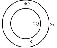
2. (a) Deduce the expression for the torque acting on a dipole of dipole moment p¯ in the presence of a uniform electric field E¯ . (b) Consider two hollow concentric spheres, S1 and S2, enclosing charges 2Q and 4Q respectively as shown in the figure.
(i) Find out the ratio of the electric flux through them.
(ii) How will the electric flux through the sphere S1 change if a medium of dielectric constant 'εr' is introduced in the space inside S1 in place of air ? Deduce the necessary expression.
3. (a) Define electric dipole moment. Is it a scalar or a vector? Derive the expression for the electric field of a dipole at a point on the equatorial plane of the dipole.
(b) Draw the equipotential surfaces due to an electric dipole. Locate the points where the potential due to the dipole is zero.
4. Using Gauss”s law deduce the expression for the electric field due to a uniformly charged spherical conducting shell of radius R at a point (i) outside and (ii) inside the shell.
Plot a graph showing variation of electric field as a function of r > R and r< R. (r being the distance from the centre of the shell)
5. (a) Using Gauss law, derive an expression for the electric field intensity at any point outside a uniformly charged thin spherical shell of radius R and charge density s C/m 2 . Draw the field lines when the charge density of the sphere is (i) positive, (ii) negative.
(b) A uniformly charged conducting sphere of 2×5 m in diameter has a surface charge density of 100 mC/m 2 . Calculate the charge on the sphere (ii) total electric flux passing through the sphere.
6. State Gauss’s theorem in electrostatics. Using this theorem, derive an expression for the electric field intensity to infinity long straight wire of liner charge density 𝜆𝐶𝑚−1 Derive an expression for the electric field intensity to infinity at a point near a thin infinite plane sheet of charge density 𝛼𝐶𝑚−2
7. (a) State Kirchhoff's rules and explain on what basis they are justified.
(b) Two cells of emfs E1 and E2 and internal resistances r1 and r2 are connected in parallel. Derive the expression for the (i) emf and (ii) internal resistance of a single equivalent cell which can replace this combination.
8. State the underlying principal of potentiometer.
Describe briefly, giving the necessary circuit diagram, how a potentiometer is used to measure the internal resistance of a given cell.
Explain how potentiometer can be used to compare the emfs of two primary cells.
9. (a) State Ampere's circuital law. Use this law to obtain the expression for the magnetic field inside an air cored toroid of average radius 'r', having 'n' turns per unit length and carrying a steady current I.
(b) An observer to the left of a solenoid of N turns each of cross section area 'A' observes that a steady current I in it flows in the clockwise direction. Depict the magnetic field lines due to the solenoid specifying its polarity and show that it acts as a bar magnet of magnetic momentum = NIA.
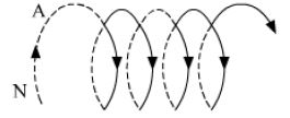
10. (a) Deduce an expression for the frequency of revolution of a charged particle in a magnetic field and show that it is independent of velocity or energy of the particle.
(b) Draw a schematic sketch of a cyclotron. Explain, giving the essential details of its construction, how it is used to accelerate the charged particles.
11. (a) Draw a labelled diagram of a moving coil galvanometer. Describe briefly its principle and working.
(b) Answer the following:
(i) Why is it necessary to introduce a cylindrical soft iron core inside the coil of a galvanometer?
(ii) Increasing the current sensitivity of a galvanometer may not necessarily increase its voltage sensitivity. Explain, giving reason.
12. (a) Draw a schematic sketch of a cyclotron. Explain clearly the role of crossed electric and magnetic field in accelerating the charge. Hence derive the expression for the kinetic energy acquired by the particles.
(b) An 𝛼-particle and a proton are released from the centre of the cyclotron and made to accelerate.
(i) Can both be accelerated at the same cyclotron frequency? Give reason to justify your answer.
(ii) When they are accelerated in turn, which of the two will have higher velocity at the exit slit of the does?
13. (a) Using Biot − Savart”s law, derive the expression for the magnetic field in the vector form at a point on the axis of a circular current loop.
(b) What does a toroid consist of? Find out the expression for the magnetic field inside a toroid for N turns of the coil having the average radius r and carrying a current I. Show that the magnetic field in the open space inside and exterior to the toroid is zero.
14. (a) Write the expression for the force,, acting on a charged particle of charge ‘q’, moving with a velocity v in the presence of both electric field F and magnetic field B. Obtain the condition under which the particle moves undeflected through the fields.
(b) A rectangular loop of size l x b carrying a steady current I is placed in a uniform magnetic field B. Prove that the torque r acting on the loop is give by where m is the magnetic moment of the loop.
15. (a) Explain, giving reasons, the basic difference in converting a galvanometer into (i) a voltmeter and (ii) an ammeter.
(b) Two long straight parallel conductors carrying steady currents I1 and I2 are separated by a distance 'd'. Explain briefly, with the help of a suitable diagram, how the magnetic field due to one conductor acts on the other. Hence deduce the expression for the force acting between the two conductors. Mention the nature of this force.
16. (a) Draw a labelled diagram of a moving coil galvanometer. Describe briefly its principle and working. (b) Answer the following:
(i) Why is it necessary to introduce a cylindrical soft iron core inside the coil of a galvanometer?
(ii) Increasing the current sensitivity of a galvanometer may not necessarily increase its voltage sensitivity. Explain, giving reason.
17. A long straight wire of a circular cross-section of radius ‘a’ carries a steady current ‘I’. The current is uniformly distributed across the cross-section. Apply Ampere’s circuital law to calculate the magnetic field at a point ‘r’ in the region for (i) r <a and (ii) r >a. Two infinitely long straight parallel wires, '1' and '2', carrying steady currents I1 and I2 in the same direction are separated by a distance d. Obtain the expression for the magnetic field B due to the wire '1' acting on wire '2'. Hence find out, with the help of a suitable diagram, the magnitude and direction of this force per unit length on wire '2' due to wire '1'. How does the nature of this force changes if the currents are in opposite direction? Use this expression to define the S.I. unit of current.
18. (a) Show that a planar loop carrying a current I, having N closely wound turns and area of cross-section A, possesses a magnetic moment M=N I A
(b) When this loop is placed in a magnetic field B, find out the expression for the torque acting on it.
(c) A galvanometer coil of 50 W resistance shows full scale deflection for a corrent of 5 mA. How will you convert this galvanometer into a voltmeter of range 0 to 15 V?
19. (a) State Lenz’s law. Give one example to illustrate this law. “The Lenz’s law is a consequence of the principle of conservation of energy.” Justify this statement.
(b) Deduce an expression for the mutual inductance of two long co-axial solenoids but having different radii and different number of turns.
20. (a) Define mutual inductance and write its S.I. units.
(b) Derive an expression for the mutual inductance of two long co-axial solenoids of same length wound one over the other,
(c) In an experiment, two coils c1 and c2 are placed close to each other. Find out the expression for the emf induced in the coil c1 due to a change in the current through the coil c2.
21. (a) What are eddy currents? How are these currents reduced in the metallic cores of transformers?
(b) A step down transformer operates on a 2×5 KV line. It supplies a load with 20 A. The ratio of the primary winding to the secondary is 10: 1. If the transformer is 90% efficient, calculate:
(i) the power output,
(ii) the voltage, and (iii) the current in the secondary.
22. State the working principle of an AC generator with the help of a labelled diagram.
Derive an expression for the instantaneous value of the emf induced in coil.
Why is the emf maximum when the plane of the armature is parallel to the magetic field?
23. A series LCR circuit is connected to an ac source having voltage v = vmsin wt. Derive the expression for the instantaneous current J and its phase relationship to the applied voltage.
Obtain the condition for resonance to occur. Define ‘power factor’. State the conditions under which it is (i) maximum and (ii) minimum.
24. Draw a necessary arrangement for winding of primary and secondary coils in a step-up transformer. State its underlying principle and derive the relation between the primary and secondary voltages in terms of number of primary and secondary turns. Mention the two basic assumptions used in obtaining the above relation. State any two causes of energy loss in actual transformers.
25. Draw a labelled diagram of a step-up transformer and explain briefly its working.
Deduce the expressions for the secondary voltage and secondary current in terms of the number of turns of primary and secondary windings.
How is the power transmission and distribution over long distances done with the use of transformers?
26. (a) A point object 'O' is kept in a medium of refractive index n1 in front of a convex spherical surface of radius of curvature R which separates the second medium of refractive index n2from the first one, as shown in the figure. Draw the ray diagram showing the image formation and deduce the relationship between the object distance and the image distance in terms of n1, n2 and R.
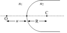
(b) When the image formed above acts as a virtual object for a concave spherical surface separating the medium n2 from n1 (n2 > n1), draw this ray and write the similar relation. Hence obtain lens maker’s formula.
27. Draw a labelled ray diagram of a refracting telescope. Define its magnifying power and write the expression for it. Write two important limitations of a refracting telescope over a reflecting type telescope.
28. Derive an expression for the magnifying power of a compound microscope when the image is formed at the near point.
(a) A ray of light is incident in glass on a glass-water boundary. The angle of incidence is 50°.
Calculate the angle of refraction. Refractive index of glass = 1.50; refractive index of water = 1.33.
29. Derive an expression for the refractive index of prism material in terms of angle of the prism and the angle of minimum deviation.
(a) The refractive index of the material of a prism of 60° angle for yellow light is (2)1/2. Determine the angle of minimum deviation
30. Trace the rays of light showing the formation of an image due to a point object placed on the axis of a spherical surface separating the two media of refractive indices n1 and n2 . Establish the relation between the distances of the object, the image and the radius of curvature from the central point of the spherical surface.
Hence, derive the expression of the lens maker’s formula.
31. (a) For a ray of light travelling from a denser medium of refractive index n1 to a rarer medium ofrefractive index n2 , prove that 𝑛1/𝑛2 = sin𝑖𝑐 , where icis the critical angle of incidence for the media.
(b) Explain with the help of a diagram, how the above principle is used for transmission of video signals using optical fibres.
32. Draw a labelled ray diagram of an astronomical telescope, in the normal adjustment position and write the expression for its magnifying power. An astronomical telescope uses an objective lens of focal length 15 m and eye-lens of focal length 1 cm. What is the angular magnification of the telescope?
If this telescope is used to view moon, what is the diameter of the image of moon formed by the objective lens? (Diameter of moon =3×5 ´106 m and radius of lunar orbit =3×8 ´108 m).
33. (a) With the help of a suitable ray diagram, derive the mirror formula for a concave mirror.
(b) The near point of a hypermetropic person is 50 cm from the eye. What is the power of the lens required to enable the person to read clearly a book held at 25 cm from the eye?
34. (a) Draw a ray diagram for formation of image of a point object by a thin double convex lens having radii of curvatures R1 and R2 and hence derive lens maker’s formula.
(b) Define power of a lens and give its S.I. units. If a convex lens of focal length 50 cm is placed in contact coaxially with a concave lens of focal length 20 cm, what is the power of the combination?
35. (a) Using Huygens's construction of secondary wavelets explain how a diffraction pattern is obtained on a screen due to a narrow slit on which a monochromatic beam of light is incident normally.
(b) Show that the angular width of the first diffraction fringe is half that of the central fringe.
(c) Explain why the maxima at 𝜃 = (𝑛+1/2) 𝜆/𝑎 become weaker and weaker with increasing n.
36. (a) In Young's double slit experiment, describe briefly how bright and dark fringes are obtained on the screen kept in front of a double slit. Hence obtain the expression for the fringe width.
(b) The ratio of the intensities at minima to the maxima in the Young's double slit experiment is 9 : 25. Find the ratio of the widths of the two slits.
37. (a) Describe briefly how a diffraction pattern is obtained on a screen due to a single narrow slit illuminated by a monochromatic source of light. Hence obtain the conditions for the angular width of secondary maxima and secondary minima.
(b) Two wavelengths of sodium light of 590 nm and 596 nm are used in turn to study the diffraction taking place at a single slit of aperture 2 × 10⁻⁶ m. The distance between the slit and the screen is 1·5 m. Calculate the separation between the positions of first maxima of the diffraction pattern obtained in the two cases.
38. (a) In Young's double slit experiment, derive the condition for
(i) constructive interference and
(ii) destructive interference at a point on the screen.
(b) A beam of light consisting of two wavelengths, 800 nm and 600 nm is used to obtain the interference fringes in a Young's double slit experiment on a screen placed 1 · 4 m away. If the two slits are separated by 0·28 mm, calculate the least distance from the central bright maximum where the bright fringes of the two wavelengths coincide.
39. (a) Use Huygens' principle to show the propagation of a plane wavefront from a denser medium to a rarer medium. Hence find the ratio of the speeds of wave fronts in the two media.
(b) (i) Why does an unpolarised light incident on a Polaroid get linearly polarised ?
(ii) Derive the expression of Brewster's law when unpolarised light passing from a rarer to a denser medium gets polarised on reflection at the inteface.
40. (a) How does an unpolarized light incident on a polaroid get polarized? Describe briefly, with the help of a necessary diagram, the polarization of light by reflection from a transparent medium.
(b) Two polaroids “A”and “B” are kept in crossed position. How should a third polaroid “C” be placed between them so that the intensity of polarized light transmitted by polaroid B reduces to 1/8th of the intensity of unpolarized light incident on A?
41. (a) What is plane polarised light? Two polaroids are placed at 90° to each other and the transmitted intensity is zero. What happens when one more polaroid is placed between these two, bisecting the angle between them ? How will the intensity of transmitted light vary on further rotating the third polaroid?
(b) If a light beam shows no intensity variation when transmitted through a polaroid which is rotated, does it mean that the light is unpolarised ? Explain briefly.
42. Using Bohr”s postulates, derive the expression for the frequency of radiation emitted when electron in hydrogen atom undergoes transition from higher energy state (quantum number ni) to the lower state, (nf). When electron in hydrogen atom jumps from energy state ni = 4 to nf = 3, 2, 1, identify the spectral series to which the emission lines belong.
43. (a) Draw the plot of binding energy per nucleon (BE/A) as a function of mass number A. Write two important conclusions that can be drawn regarding the nature of nuclear force.
(b) Use this graph to explain the release of energy in both the processes of nuclear fusion and fission.
(c) Write the basic nuclear process of neutron undergoing 𝛼-decay. Why is the detection of neutrinos found very difficult?
44. Write Einstein”s photoelectric equation and point out any two characteristic properties of photons on which this equation is based. Briefly explain the three observed features which can be explained by this equation. The ground state energy of hydrogen atom is −13.6 eV. If and electron make a transition from the energy level −0.85 eV to −3.4 eV, calculate spectrum does his wavelength belong?
45. (a) Explain the formation of ‘depletion layer' and ‘barrier potential’ in a p-n junction.
(b) With the help of a labelled circuit diagram explain the use of a p-n junction diode as a full wave rectifier. Draw the input and output waveforms.
46. (a) Describe briefly, with the help of a diagram, the role of the two important processes involved in the formation of a p-n junction.
(b) Name the device which is used as a voltage regulator. Draw the necessary circuit diagram and explain its working.
47. a) Give a circuit diagram of a common emitter amplifier using an n-p-n transistor. Draw the input and output waveforms of the signal. Write the expression for its voltage gain.
(b) Identify the equivalent gate for the following circuit and write its truth table.

48. (i) With the help of circuit diagrams distinguish between forward biasing and reverse biasing of a p-n junction diode.
(ii) Draw V-I characteristics of a p-n junction diode in (a) forward bias, (b) reverse bias
49. (a) Draw I-V characteristics of a Zener diode.
(b) Explain with the help of a circuit diagram, the use of a Zener diode as a voltage-regulator.
(c) A photodiode is operated under reverse bias although in the forward bias the current is known to be more than the current in the reverse bias. Explain giving reason.
50. Explain how a transistor in active state exhibits a low resistance at its emitter base junction and high resistance at its base collector junction. Draw a circuit diagram and explain the operation of a transistor as a switch.
Question Q1) (a) State the working of a.c. generator with the help of a labelled diagram.
(b) The coil of an a.c. generator having N turns, each of area A, is rotated with a constant angular velocity . Deduce the expression for the alternating emf generated in the coil.
(c) What is the source of energy generation in this device?
Answer:
(a) **Working and Principle:** An AC generator operates on the principle of electromagnetic induction. When a closed armature coil is rotated in a uniform magnetic field, the magnetic flux linking the coil continuously changes, inducing an electromotive force (emf) and an alternating current inside the circuit.
**Main Parts of an AC Generator:**
- **Armature:** A rectangular coil ABCD consisting of many turns of insulated copper wire.
- **Field Magnets:** Strong electromagnet poles that produce a uniform magnetic field.
- **Slip Rings:** Two hollow metal rings \( R_1 \) and \( R_2 \) connected to the ends of the armature coil, which rotate along with it.
- **Brushes:** Two stationary flexible carbon or metal brushes \( B_1 \) and \( B_2 \) in sliding contact with the slip rings to transfer current to the load.
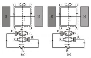
Let \( N \) be the number of turns in the coil, \( A \) be the area of each turn, and \( B \) be the strength of the magnetic field.
When the coil rotates with a constant angular velocity \( \omega \), the angle \( \theta \) between the magnetic field vector and the area vector at any instant \( t \) is:
\( \theta = \omega t \)
The magnetic flux \( \Phi \) linked with the coil at this instant is:
\( \Phi = N B A \cos\theta = N B A \cos(\omega t) \)
According to Faraday's law of electromagnetic induction, the induced emf \( e \) is:
\( e = -\frac{d\Phi}{dt} = -\frac{d}{dt} [N B A \cos(\omega t)] \)
\( e = -N B A (-\omega \sin(\omega t)) = N B A \omega \sin(\omega t) \)
Let \( e_0 = N B A \omega \) represent the peak value of the induced emf. Then:
\( e = e_0 \sin(\omega t) \).
(c) **Source of Energy:** The source of energy is the external **mechanical energy** used to rotate the armature coil inside the magnetic field, which is converted into electrical energy.
In simple words: An AC generator converts mechanical rotational work into electricity. As the coil spins, the changing angle constantly alters the magnetic lines passing through it, generating an alternating voltage.
Exam Tip: Be sure to write the final formula \( e = e_0 \sin(\omega t) \) clearly and identify that the mechanical work done to rotate the coil is the primary energy input.
Question Q2) Draw the plot of binding energy per nucleon (BE/A) as a function of mass number A. Write two important conclusions that can be drawn regarding the nature of nuclear force.
(b) Use this graph to explain the release of energy in both the processes of nuclear fusion and fission.
(c) Write the basic nuclear process of neutron undergoing --decay. Why is the detection of neutrinos found very difficult?
Answer:
(a) **Binding Energy Curve:**
**Conclusions on Nuclear Force:**
1. **Strong Attraction:** The nuclear force is highly attractive and strong enough to yield a high binding energy of several MeV per nucleon, overcoming electrostatic repulsion.
2. **Short-range saturation:** The constant value of binding energy in the range \( A = 30 \) to \( 170 \) indicates that the nuclear force is saturated and only acts on immediate neighbors.
(b) **Energy Release Explanation:**
- **Nuclear Fission:** Heavy nuclei (\( A > 170 \), e.g., \( A = 240 \)) have lower binding energy per nucleon compared to intermediate-mass nuclei. If a heavy nucleus splits into two lighter fragments (near \( A \approx 120 \)), the nucleons in the products become more tightly bound, releasing the difference in potential energy.
- **Nuclear Fusion:** Extremely light nuclei (\( A < 10 \)) have low binding energy per nucleon. When they merge to form a heavier, more stable nucleus, the binding energy per nucleon increases significantly, releasing massive energy.
(c) **Neutron Decay Process:**
\( n \rightarrow p + e^- + \bar{\nu} \)
**Neutrino Detection:** Neutrinos are uncharged, almost massless particles that interact extremely weakly with matter, allowing them to pass through solid objects easily, making detection difficult.
In simple words: The graph shows how tightly packed a nucleus is. Splitting huge atoms (fission) or merging tiny ones (fusion) both move the products toward the highly stable peak near Iron-56, releasing energy in the process.
Exam Tip: Be sure to include the antineutrino symbol (\( \bar{\nu} \)) in the neutron decay equation to receive full marks.
Question Q3)(a) Draw a schematic sketch of a cyclotron. Explain clearly the role of crossed electric and magnetic field in accelerating the charge. Hence derive the expression for the kinetic energy acquired by the particles.
(b) An Alpha particle and a proton are released from the centre of the cyclotron and made to accelerate.
(i) Can both be accelerated at the same cyclotron frequency? Give reason to justify your answer.
(ii) When they are accelerated in turn, which of the two will have higher velocity at the exit slit of the does?
Answer:
(a) **Cyclotron Working and Diagram:*
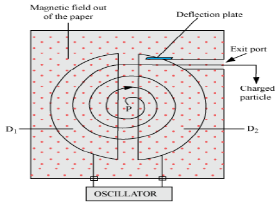
- **Magnetic Field:** Keeps the particle moving in a circular orbit within the metallic Dees.
- **Electric Field:** Exists only in the gap between the two Dees and accelerates the particle when crossing, shifting it to larger circular orbits.
**Kinetic Energy Derivation:**
\( q v B = \frac{m v^2}{R} \implies v = \frac{q B R}{m} \)
\( K.E. = \frac{1}{2} m v^2 = \frac{q^2 B^2 R^2}{2m} \).
(b) (i) **Cyclotron Frequency Comparison:** No, they cannot. The frequency is \( \nu_c = \frac{q B}{2\pi m} \). Since the mass-to-charge ratio of a proton is \( \frac{m}{q} \) and that of an alpha particle is \( \frac{4m}{2q} = \frac{2m}{q} \), the cyclotron frequency for the proton is twice that of the alpha particle.
(ii) **Exit Velocity Comparison:** The velocity at the exit is \( v = \frac{q B R}{m} \).
For the proton: \( v_p \propto \frac{q}{m} \)
For the alpha particle: \( v_{\alpha} \propto \frac{2q}{4m} = \frac{q}{2m} \)
Thus, the **proton** will exit with a higher velocity.
In simple words: The magnetic field steers the charge in circles inside the metal shells, while the electric field kicks it forward in the gap. Because the proton is lighter, it responds faster to these kicks, exiting with a higher velocity than the heavier alpha particle.
Exam Tip: State clearly that the time period of rotation inside a Dee is independent of the speed and radius of the orbit.
Question Q4) (a) State the importance of coherent sources in the phenomenon of interference.
(b) In Young’s double slit experiment to produce interference pattern, obtain the conditions for constructive and destructive interference. Hence deduce the expression for the fringe width.
(c) How does the fringe width get affected, if the entire experimental apparatus of Young is immersed in water?
Answer:
(a) **Coherent Sources:** Coherent sources are essential for producing a stable and observable interference pattern. They emit light waves of the same frequency with a constant or zero phase difference over time. Independent sources cannot maintain a constant phase relationship due to rapid, random phase changes within atoms.
(b) **Derivation:**
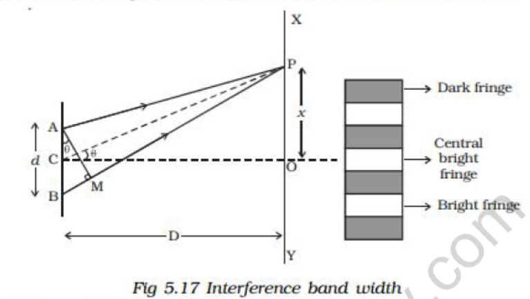
Let \( d \) be the separation between the slits and \( D \) be the distance to the screen. For any point \( P \) at a distance \( x \) from the center of the screen, the path difference is:
\( \delta = \frac{x d}{D} \)
- **Constructive Interference (Bright Fringes):** \( \frac{x d}{D} = n \lambda \implies x_n = n \frac{D \lambda}{d} \)
- **Destructive Interference (Dark Fringes):** \( \frac{x d}{D} = (2n - 1)\frac{\lambda}{2} \implies x_n = (2n - 1)\frac{D \lambda}{2d} \)
The distance between two consecutive bright fringes is:
\( \beta = x_{n+1} - x_n = \frac{D \lambda}{d} \).
(c) **Effect of Water:** When immersed in water of refractive index \( n \), the wavelength decreases to \( \lambda' = \frac{\lambda}{n} \). Consequently, the fringe width decreases by the same factor: \( \beta' = \frac{\beta}{n} \).
In simple words: Coherent light sources make sure the waves stay in step. When placed in water, light waves compress, which squeezes the bright and dark stripes closer together on the screen.
Exam Tip: Be sure to write the formula \( \beta' = \frac{\beta}{n} \) to show that the fringe pattern will contract in a medium with a higher refractive index.
Question Q5)(a) Write briefly any two factors which demonstrate the need for modulating a signal. Draw a suitable diagram to show amplitude modulation using a sinusoidal signal as the modulating signal.
(b) A transmitting antenna at the top of a tower has a height of 20 m and the height of the receiving antenna is 45 m. Calculate the maximum distance between them for satisfactory communication in LOS mode. (Radius of the Earth = 6.4 X 10⁶ m)
Answer:
(a) **Need for Modulation:**
1. **Size of Antenna:** To transmit a wave effectively, the antenna size must be comparable to \( \lambda/4 \). Low-frequency audio signals have extremely long wavelengths, requiring impossibly large antennas unless modulated to high frequencies.
2. **Power Radiation:** The power radiated by an antenna increases with frequency (\( P \propto \nu^2 \)), so modulation ensures a strong, high-power transmission.
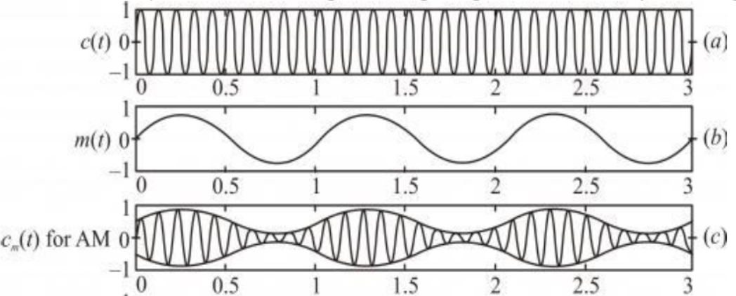
(b) **Numerical Calculation:**
Given \( h_T = 20\text{ m} \), \( h_R = 45\text{ m} \), and \( R = 6.4 \times 10^6\text{ m} \):
\( d_m = \sqrt{2 R h_T} + \sqrt{2 R h_R} \)
\( d_m = \sqrt{2 \times 6.4 \times 10^6 \times 20} + \sqrt{2 \times 6.4 \times 10^6 \times 45} \)
\( d_m = \sqrt{256 \times 10^6} + \sqrt{576 \times 10^6} \)
\( d_m = 16000\text{ m} + 24000\text{ m} = 40000\text{ m} = 40\text{ km} \).
Therefore, the maximum distance is \( 40\text{ km} \).
In simple words: Low-frequency sounds can't travel far and would require giant antennas. By riding on a high-frequency carrier wave (modulation), the signal can be sent efficiently. For the given antenna heights, line-of-sight signal reach is 40 kilometers.
Exam Tip: Be careful during square-root evaluations. Always convert final distance results to kilometers to keep your answers professional.
Question Q6)(a) Draw a labelled ray diagram of a refracting telescope. Define its magnifying power and write the expression for it.
(b) Write two important limitations of a refracting telescope over a reflecting type telescope.
(c) A giant refracting telescope at an observatory has an objective lens of focal length 15 m. If an eyepiece lens of focal length 1.0 cm is used, find the angular magnification of the telescope.
Answer:
(a) **Ray Diagram:**
**Magnifying Power Definition:** It is the ratio of the angle subtended by the final image at the eye to the angle subtended by the object at the objective lens.
\( m = -\frac{f_o}{f_e} \).
(b) **Limitations:**
1. It suffers from **chromatic aberration** due to dispersion of light through the large objective lens.
2. Large lenses are heavy, making them difficult and expensive to manufacture and support by their edges without distortion.
(c) **Calculation:**
Given \( f_o = 15\text{ m} = 1500\text{ cm} \), \( f_e = 1.0\text{ cm} \):
\( m = -\frac{f_o}{f_e} = -\frac{1500}{1} = -1500 \).
(The negative sign indicates an inverted image).
In simple words: Magnifying power is how much larger an object looks through the telescope. Heavy lenses in refracting telescopes cause color blur and mechanical sagging. A 15-meter objective with a 1 cm eyepiece yields an angular magnification of 1500 times.
Exam Tip: Be sure to keep the focal lengths in the same units (either both in meters or both in centimeters) before division.
Question Q7)(a) Draw a plot showing the variation of photoelectric current with collector plate potential for two different frequencies, v1>v2, of incident radiation having the same intensity. In which case will the stopping potential be higher? Justify your answer.
(b) The graph shows the variation of stopping potential with frequency of incident radiation for two photosensitive metals A and B. Which one of the two has higher value of work-function? Justify your answer.
Answer:
(a) **Photoelectric Current vs Potential Graph:**
The stopping potential is higher (more negative) for the higher frequency \( \nu_1 \) (i.e., \( V_{o1} > V_{o2} \)). Since the kinetic energy of emitted electrons depends linearly on frequency (\( K = e V_o = h\nu - \phi \)), higher frequency photons eject faster electrons, requiring a stronger opposing voltage to stop them.
(b) **Work Function Analysis:**
According to the graph, the threshold frequency of metal A (\( \nu_0 \)) is greater than that of metal B (\( \nu'_0 \)). Since the work function is directly proportional to the threshold frequency (\( \phi = h \nu_0 \)), **metal A** has a higher work-function.
In simple words: Higher frequency light carries more energetic photons, which launch faster electrons, requiring a higher stopping voltage. A higher threshold frequency on the graph means a metal needs more energy just to start releasing electrons, indicating a higher work-function.
Exam Tip: Relate the intercept of the stopping potential versus frequency graph directly to the threshold frequency to justify your choice of the higher work-function metal.
Question Q8) Describe briefly, with the help of a circuit diagram, how a potentiometer is used to determine the internal resistance of a cell.
Answer:
**Potentiometer Setup and Working:**
A steady current is passed through the primary potentiometer wire AB from a driver cell. The cell of interest (emf \( E \) and internal resistance \( r \)) is connected in the secondary circuit, with a parallel resistance box \( R \) controlled by key \( K_2 \).
1. **Key \( K_2 \) Open:** The cell is on open circuit. We find the balancing length \( l_1 \). Since no current is drawn:
\( E = k l_1 \) --- (1)
2. **Key \( K_2 \) Closed:** The cell discharges through the resistance \( R \). We find the new balancing length \( l_2 \) corresponding to the terminal voltage \( V \):
\( V = k l_2 \) --- (2)
Dividing equation (1) by (2):
\( \frac{E}{V} = \frac{l_1}{l_2} \) --- (3)
Using the cell relationship \( E = I(R + r) \) and \( V = IR \):
\( \frac{E}{V} = \frac{R + r}{R} = 1 + \frac{r}{R} \) --- (4)
Equating (3) and (4):
\( 1 + \frac{r}{R} = \frac{l_1}{l_2} \implies r = R \left( \frac{l_1}{l_2} - 1 \right) \).
Using this relation, the internal resistance is calculated.
In simple words: First, we measure the potential drop on open circuit (no current), giving length 1. Then we connect an external resistor and measure the potential drop while current is flowing, giving a smaller length 2. The difference between these measurements lets us compute the cell's internal resistance.
Exam Tip: State the final equation \( r = R \left( \frac{l_1}{l_2} - 1 \right) \) clearly. Remember that \( l_1 \) must always be larger than \( l_2 \) because \( E > V \).
Question Q9)(a) Derive the expression for the radius of the nth orbit of hydrogen atom using Bohr’s postulates. Show graphically the (nature of) variation of the radius of orbit with the principal quantum number, n.
(b) The ground state energy of hydrogen atom is – 13.6 eV. What are the potential and kinetic energy of an electron in the 3rd excited state?
Answer:
(a) **Radius Derivation:**
For an electron revolving in the \( n^{\text{th}} \) orbit of radius \( r_n \) around a nucleus of charge \( Ze \):
\( \frac{m v^2}{r_n} = \frac{1}{4\pi\varepsilon_0} \frac{Z e^2}{r_n^2} \implies m v^2 r_n = \frac{Z e^2}{4\pi\varepsilon_0} \) --- (1)
According to Bohr's quantization postulate:
\( m v r_n = \frac{n h}{2\pi} \implies v = \frac{n h}{2\pi m r_n} \) --- (2)
Substituting (2) into (1):
\( m \left( \frac{n h}{2\pi m r_n} \right)^2 r_n = \frac{Z e^2}{4\pi\varepsilon_0} \implies \frac{n^2 h^2}{4\pi^2 m r_n} = \frac{Z e^2}{4\pi\varepsilon_0} \)
\( \implies r_n = \frac{n^2 h^2 \varepsilon_0}{\pi m Z e^2} \).
For Hydrogen (\( Z = 1 \)), \( r_n \propto n^2 \). This quadratic variation forms an upward-curving parabola.
(b) **Calculation:**
The 3rd excited state corresponds to the \( n = 4 \) energy level.
The total energy in this state is:
\( E_4 = -\frac{13.6}{n^2} = -\frac{13.6}{16} = -0.85\text{ eV} \).
The kinetic energy is:
\( K.E. = -E_4 = +0.85\text{ eV} \).
The potential energy is:
\( P.E. = 2 E_4 = 2 \times (-0.85) = -1.70\text{ eV} \).
In simple words: Equating electrostatic pull to centripetal force and applying Bohr's angular momentum rule shows that orbit radius grows with the square of the orbit number. At the 4th level (3rd excited state), the total energy is -0.85 eV, making the kinetic energy +0.85 eV and the potential energy -1.70 eV.
Exam Tip: Be careful with terminology: '3rd excited state' means the fourth energy level (\( n = 4 \)), not \( n = 3 \).
Question Q10)(a) Two wires of equal length, one of copper and the other of manganin have the same resistance. Which wire is thicker?
(b) Define mobility of electron in a conductor. How does electron mobility change when (i) temperature of conductor is decreased (ii) Applied potential difference is doubled at constant temperature?
Answer:
(a) **Thickness Comparison:**
Since resistance is \( R = \rho \frac{l}{A} \), for identical length \( l \) and resistance \( R \), the area of cross-section is directly proportional to resistivity (\( A \propto \rho \)). Because manganin has a higher resistivity than copper (\( \rho_{\text{manganin}} > \rho_{\text{copper}} \)), the cross-sectional area of the manganin wire must be larger. Thus, the **manganin wire** is thicker.
(b) **Electron Mobility:**
Mobility (\( \mu \)) is defined as the magnitude of drift velocity acquired by an electron per unit applied electric field:
\( \mu = \frac{v_d}{E} = \frac{e \tau}{m} \).
- **(i) Temperature Decreased:** Cooling the conductor reduces lattice vibrations, which increases the relaxation time (\( \tau \)). Consequently, the electron mobility **increases**.
- **(ii) Potential Difference Doubled:** Mobility depends only on temperature-dependent relaxation time and electron constants. Therefore, changing the voltage at a constant temperature has **no effect** on mobility.
In simple words: Manganin resists electricity much more than copper, so a manganin wire must be made thicker to have the same resistance. Electron mobility is how easily electrons flow. Cooling the wire lets them flow more easily, but changing the voltage has no effect on this native ease of movement.
Exam Tip: Use the formula \( \mu = \frac{e\tau}{m} \) to justify why mobility changes only with temperature-dependent relaxation time \( \tau \).
Question Q11) Draw V I characteristics of a p-n junction diode. Answer the following questions, giving reasons:
(i) Why is the current under reverse bias almost independent of the applied potential up to a critical voltage?
(ii) Why does the reverse current show a sudden increase at the critical voltage?
(iii) Name any semiconductor device which operates under the reverse bias in the breakdownregion.
Answer:
**V-I Characteristics Graph:**
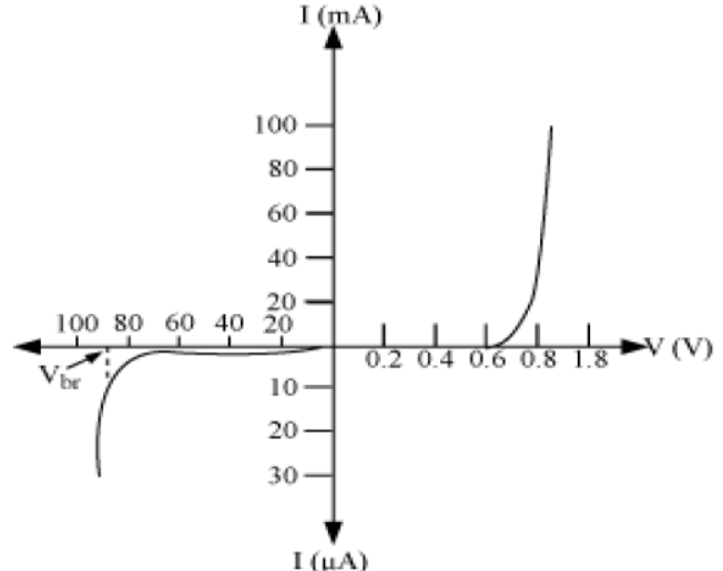
(i) Under reverse bias, the major charge carriers are pulled away from the junction, leaving only the minority carriers to drift across. Since the number of minority charge carriers is extremely small and depends only on temperature, the reverse current remains constant and independent of the applied voltage.
(ii) At the critical breakdown voltage, the strong electric field accelerates the minority carriers to high speeds, causing them to collide with and break covalent bonds (avalanche breakdown). This leads to a sudden, massive generation of electron-hole pairs, resulting in a sharp current spike.
(iii) The **Zener diode** is a semiconductor device designed specifically to operate in this reverse breakdown region.
In simple words: In reverse bias, the current is blocked except for a tiny leakage of minority charges. If the reverse voltage gets too high, it triggers a chain-reaction breakdown that allows a massive surge of current to flow.
Exam Tip: Be sure to name 'Zener diode' as the standard device operating in the reverse breakdown region for regulating voltage.
Question Q12) The magnetic field in a plane electromagnetic wave is given by tesla.
B_y = 2 \times 10^{-7} \sin(0.5 \times 10^3 x + 1.5 \times 10^{11} t) tesla.
(a) What is the wavelength and frequency of the wave?
(b) Write an expression for the electric field.
(c) A parallel plate capacitor is being charged. Show that the displacement current across an area in the region between the plates and parallel to it is equal to the conduction current in the connecting wires.
Answer:
(a) Comparing the wave equation with the standard form:
\( B_y = B_0 \sin(k x + \omega t) \)
We find:
\( k = \frac{2\pi}{\lambda} = 0.5 \times 10^3 \implies \lambda = \frac{2 \times 3.14}{0.5 \times 10^3} \approx 1.26 \times 10^{-2}\text{ m} \).
\( \omega = 2\pi\nu = 1.5 \times 10^{11} \implies \nu = \frac{1.5 \times 10^{11}}{2 \times 3.14} \approx 2.39 \times 10^{10}\text{ Hz} = 23.9\text{ GHz} \).
(b) The peak electric field is:
\( E_0 = c B_0 = (3 \times 10^8) \times (2 \times 10^{-7}) = 60\text{ V/m} \).
Since the magnetic field is along the y-axis and the wave propagates along the x-axis, the electric field must be along the z-axis:
\( E_z = 60 \sin(0.5 \times 10^3 x + 1.5 \times 10^{11} t)\text{ V/m} \).
(c) The electric field between the capacitor plates of area \( A \) and charge \( q \) is \( E = \frac{q}{\varepsilon_0 A} \). The electric flux is:
\( \Phi_E = E A = \frac{q}{\varepsilon_0} \).
The displacement current \( I_d \) is defined as:
\( I_d = \varepsilon_0 \frac{d\Phi_E}{dt} = \varepsilon_0 \frac{d}{dt} \left( \frac{q}{\varepsilon_0} \right) = \frac{dq}{dt} \).
Since the conduction current in the wires is \( I_c = \frac{dq}{dt} \), this proves:
\( I_d = I_c \).
In simple words: Comparing the wave to standard formulas gives a wavelength of 1.26 cm and a frequency of 23.9 GHz. Inside a charging capacitor, the changing electric field creates a displacement current that is identical to the current in the wires.
Exam Tip: Remember that the wave direction (x) is perpendicular to both \( \vec{E} \) and \( \vec{B} \), ensuring the electric field is along the z-axis.
Question Q13)(i) With the help of a circuit diagram and input and output waveform explain working of half wave Rectifier.
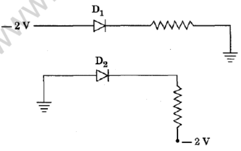
(ii) From the diagram shown below identify whether the diode D1 and D2 is forward or reverse biased and why?
Answer:
(i) **Working of Half-Wave Rectifier:**
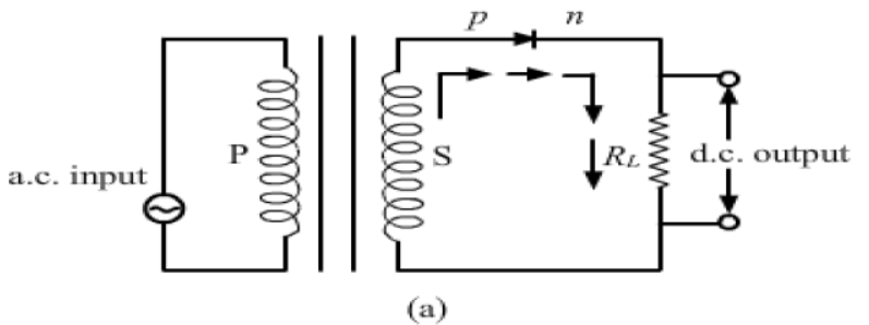
During the positive half-cycle of the input AC voltage, the diode is forward-biased, offering low resistance and allowing current to pass to the load. During the negative half-cycle, the diode is reverse-biased, offering extremely high resistance and blocking current.(ii) **Bias Identification:**
- **Diode \( D_1 \):** The p-side of the diode is connected to a lower potential (\( -2\text{ V} \)) relative to the n-side. Hence, \( D_1 \) is **reverse-biased**.
- **Diode \( D_2 \):** The p-side of the diode is connected to a higher potential (\( 0\text{ V} \) ground) compared to the n-side (\( -2\text{ V} \)). Hence, \( D_2 \) is **forward-biased**.
In simple words: A half-wave rectifier only lets the positive parts of an AC wave pass through, blocking the negative halves. In the second circuit, the diode connected to the negative voltage is reverse-biased, while the one connected to the ground is forward-biased.
Exam Tip: Clearly draw both the input AC wave and the output pulsating DC wave to show the full rectifying action.
Question Q14) (a)With the help of the diagram explain the principle and working of a moving coil galvanometer.
(b) What is the importance of the radial magnetic field and how is it produced?
(c) Why is it that while using a moving coil galvanometer as a voltmeter a high resistance in series is required in series whereas in an ammeter a shunt is used.
Answer:
(a) **Principle and Working:** When a current-carrying coil is placed in a magnetic field, it experiences a deflecting magnetic torque: \( \tau = N I A B \sin\theta \). In a radial magnetic field (\( \theta = 90^\circ \)):
\( \tau_{\text{deflecting}} = N I A B \).
This is balanced by the restoring torque of the spring \( \tau_{\text{restoring}} = k \phi \):
\( N I A B = k \phi \implies \phi = \left( \frac{N A B}{k} \right) I \).
Thus, the deflection is directly proportional to the current.
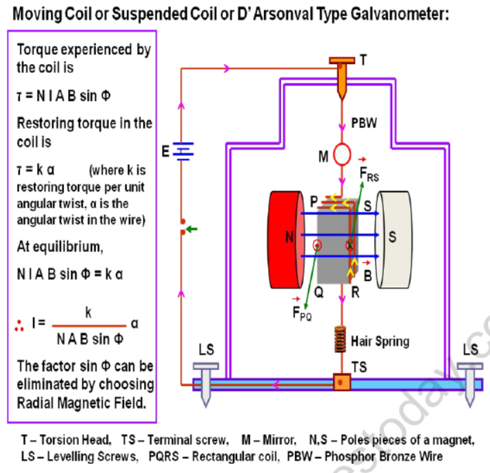
(b) **Radial Magnetic Field:** A radial field ensures that the plane of the coil remains parallel to the magnetic field lines at all angles, keeping the torque maximum and independent of the rotation angle. This makes the deflection scale completely linear. It is produced by using curved magnetic pole pieces and a soft iron core.
(c) **Reasoning:**
- **Voltmeter:** A high series resistance is required to ensure that the voltmeter has a very high resistance, drawing negligible current from the circuit so as not to alter the potential difference being measured.
- **Ammeter:** A low shunt resistance in parallel is used to minimize the overall resistance of the ammeter, ensuring it does not decrease the main current when connected in series.
In simple words: The galvanometer turns when current flows through its coil inside a radial magnetic field. We use a high series resistor for a voltmeter to block excess current, and a low parallel shunt for an ammeter to let the current pass freely.
Exam Tip: Be sure to list both purposes of the soft iron core: producing a radial field and concentrating the magnetic flux.
Question Q15) (a)Drive an expression for the force between two long parallel current carrying conductors.
(b) Use this expression to define S.I. unit of current.
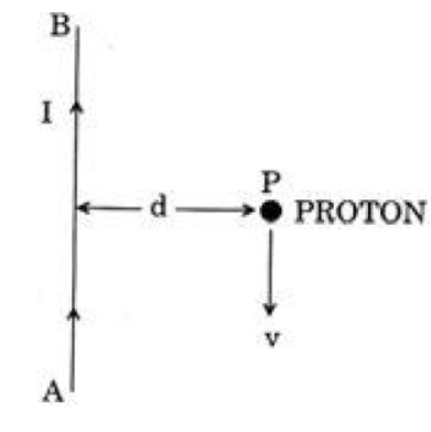
(c)A long straight wire AB carries a current I. A proton P travels with a speed v, parallel to the wire, at a distance d from it in a direction opposite to the current as shown in the figure. What is the force experienced by the proton and what is its direction?
Answer:
(a) **Force Derivation:**
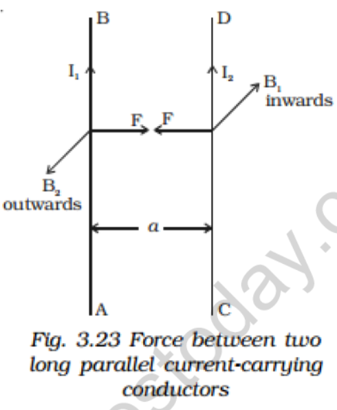
Consider two long parallel conductors carrying currents \( I_1 \) and \( I_2 \) separated by a distance \( a \). The magnetic field \( B_1 \) produced by \( I_1 \) at the second conductor is:
\( B_1 = \frac{\mu_0 I_1}{2\pi a} \).
The magnetic force \( F \) acting on a length \( l \) of the second conductor carrying current \( I_2 \) is:
\( F = I_2 l B_1 = \frac{\mu_0 I_1 I_2}{2\pi a} l \).
The force per unit length is \( \frac{F}{l} = \frac{\mu_0 I_1 I_2}{2\pi a} \). Parallel currents attract, while antiparallel currents repel.
(b) **Definition of Ampere:** One Ampere is that steady current which, when flowing through two parallel, infinitely long straight wires of negligible cross-section placed one meter apart in vacuum, produces a mutual force of \( 2 \times 10^{-7}\text{ N/m} \) of length.
(c) **Force on Proton:**
The magnetic field produced by wire AB at distance \( d \) is \( B = \frac{\mu_0 I}{2\pi d} \) (pointing into the page on the right side). Since the proton moves in the opposite direction (downward):
\( F = e v B = \frac{\mu_0 e v I}{2\pi d} \).
By applying Fleming's Left-Hand Rule, the force experienced by the proton is directed **towards the right** (away from the wire).
In simple words: Parallel currents attract each other magnetically. For the moving proton, the magnetic field of the wire deflects it with a force directed straight to the right, pushing it away from the wire AB.
Exam Tip: Keep the direction rules straight: parallel currents attract, antiparallel currents repel. Always verify the direction of \( \vec{v} \times \vec{B} \) for a positive charge.
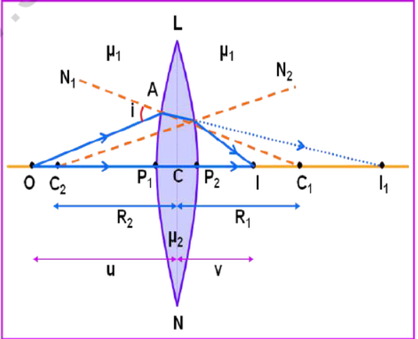
Question Q16) A point object is placed in front of a double convex lens(of refractive in n=n2/n1 with respect to air) with its spherical faces of radii of curvature R1 and R2. Show the path of rays due to refraction at first and subsequently at the second surface to obtain the formation of the real image of the object. Hence obtain the lens- maker’s formula for a thin lens. Write the assumptions and sign convention used.
Answer:
**Refraction at first surface:**
For refraction from a rarer medium \( n_1 \) to a denser medium \( n_2 \) at the first spherical surface of radius \( R_1 \), forming a virtual image at distance \( v_1 \):
\( \frac{n_2}{v_1} - \frac{n_1}{u} = \frac{n_2 - n_1}{R_1} \) --- (1)
**Refraction at second surface:**
The intermediate image at \( v_1 \) acts as a virtual object for the second surface of radius \( R_2 \), refracting back into medium \( n_1 \) to form the final real image at \( v \):
\( \frac{n_1}{v} - \frac{n_2}{v_1} = \frac{n_1 - n_2}{R_2} \) --- (2)
**Combining both surfaces:**
Adding equations (1) and (2):
\( \frac{n_1}{v} - \frac{n_1}{u} = (n_2 - n_1) \left( \frac{1}{R_1} - \frac{1}{R_2} \right) \)
\( \implies \frac{1}{v} - \frac{1}{u} = \left( \frac{n_2}{n_1} - 1 \right) \left( \frac{1}{R_1} - \frac{1}{R_2} \right) \)
If the object is at infinity (\( u = -\infty \)), the image is formed at the focus (\( v = f \)):
\( \frac{1}{f} = (n - 1) \left( \frac{1}{R_1} - \frac{1}{R_2} \right) \).
This is the lens-maker's formula
In simple words: Light bends twice when passing through a lens: first when entering the glass and second when exiting back into the air. Combining the mathematical equations for both surface refractions yields the lens-maker's formula.
Exam Tip: Be sure to write the assumptions: a thin lens with a small aperture and a point object placed on the principal axis.
Question Q17)(a)Draw a circuit diagram of n-p-n transistor amplifier in CE configuration. Under what condition does the transistor act as an amplifier?
(b) Draw input, output wave form.
(c) Define Trans-conductance.
Answer:
(a) **Amplification Condition:** A transistor acts as an amplifier when its input emitter-base junction is forward-biased with a small DC voltage, and its output collector-base junction is reverse-biased with a higher voltage, maintaining active state operation.
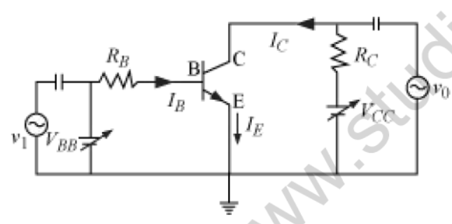
(b) **Waveform:** In a Common-Emitter (CE) amplifier, there is a \( 180^\circ \) phase difference between the input AC voltage wave and the output amplified AC voltage wave.
(c) **Trans-conductance (\( g_m \)):** It is the ratio of the change in collector current \( \Delta I_c \) to the corresponding change in emitter-base voltage \( \Delta V_{be} \) at a constant collector-emitter voltage:
\( g_m = \frac{\Delta I_c}{\Delta V_{be}} \).
In simple words: A transistor amplifies weak electrical signals by boosting current. The output signal is inverted by 180 degrees, and its trans-conductance measures how much the output current changes in response to input voltage changes.
Exam Tip: Clearly show the \( 180^\circ \) phase inversion between the input and output waveforms in your diagram to secure full marks.
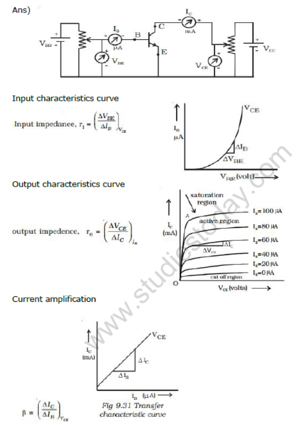
Question Q18) Draw the circuit arrangement for studying the input and output characteristics of anpn transistor in CE configuration. Draw the input and output curves.With the help of these characteristic curves define
(a) nput resistance
(b)Output resistance
(c)Current amplification factor.
Answer:
**CE Transistor Characteristics Definitions:**
(a) **Input Resistance (\( r_i \)):** It is the ratio of a small change in the base-emitter voltage \( \Delta V_{be} \) to the corresponding change in the base current \( \Delta I_b \) at a constant collector-emitter voltage:
\( r_i = \left( \frac{\Delta V_{be}}{\Delta I_b} \right)_{V_{ce}} \).
(b) **Output Resistance (\( r_o \)):** It is the ratio of a small change in the collector-emitter voltage \( \Delta V_{ce} \) to the corresponding change in the collector current \( \Delta I_c \) at a constant base current:
\( r_o = \left( \frac{\Delta V_{ce}}{\Delta I_c} \right)_{I_b} \).
(c) **Current Amplification Factor (\( \beta \)):** It is the ratio of the change in the collector current \( \Delta I_c \) to the change in the base current \( \Delta I_b \) at a constant collector-emitter voltage:
\( \beta = \left( \frac{\Delta I_c}{\Delta I_b} \right)_{V_{ce}} \).
In simple words: Input resistance is the opposition the input circuit offers to current, output resistance is the opposition from the output side, and the amplification factor (beta) represents the transistor's magnifying ratio of output to input current.
Exam Tip: State that the input curves show \( I_b \) vs \( V_{be} \) at constant \( V_{ce} \), while the output curves show \( I_c \) vs \( V_{ce} \) at constant \( I_b \).
Question Q19)Draw a graph to show the variation of the angle of deviation ‘𝛿’ with that of angle ofincidence ‘i’ for a monochromatic ray of light passing through a glass prism of refractingangle A. hence deduce the expression for the refractive index of the material of the prismin terms of the angle of prism and the angle of minimum deviation.
Answer:
**Angle of Deviation vs Angle of Incidence Curve:**
At the position of minimum deviation (\( \delta = \delta_m \)), the angle of incidence \( i \) is equal to the angle of emergence \( e \), and \( r_1 = r_2 = r \).
We know:
\( r_1 + r_2 = A \implies 2r = A \implies r = \frac{A}{2} \) --- (1)
Also:
\( A + \delta = i + e \implies A + \delta_m = 2i \implies i = \frac{A + \delta_m}{2} \) --- (2)
Applying Snell's Law:
\( n = \frac{\sin i}{\sin r} = \frac{\sin\left(\frac{A + \delta_m}{2}\right)}{\sin\left(\frac{A}{2}\right)} \).
This is the required expression for the refractive index.
In simple words: As the angle of light hitting the prism changes, the deviation bends to a minimum point where the light travels perfectly parallel to the base. At this sweet spot, Snell's Law yields the refractive index.
Exam Tip: State clearly that at minimum deviation, the refracted ray inside the prism is perfectly parallel to the base of the prism.
Question Q20) With the help of a ray diagram, show the formation of image of a point object by refraction of light at a convex spherical (convex) surface separating two media of refractive indices n1 and n2(n2> n1) respectively. Using this diagram, derive the relation.
𝑛2/𝑣 − 𝑛1/𝑢 = (𝑛2−𝑛1)/𝑅.
Also write the sign conventions used and assumptions
Answer:
**Ray Diagram:*
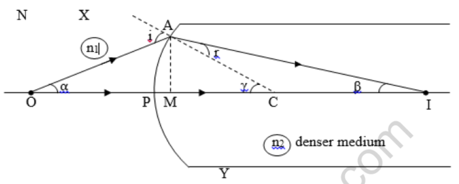
From the triangles in the ray diagram, using the exterior angle theorem, the angle of incidence \( i \) and angle of refraction \( r \) are:
\( i = \alpha + \gamma \)
\( \gamma = r + \beta \implies r = \gamma - \beta \)
According to Snell's Law:
\( n_1 \sin i = n_2 \sin r \)
For small angles:
\( n_1 i \approx n_2 r \implies n_1 (\alpha + \gamma) = n_2 (\gamma - \beta) \) --- (1)
Since the angles are small, we can write:
\( \alpha \approx \tan\alpha = \frac{AM}{PO} \)
\( \beta \approx \tan\beta = \frac{AM}{PI} \)
\( \gamma \approx \tan\gamma = \frac{AM}{PC} \)
Substituting these into (1):
\( n_1 \left( \frac{AM}{-u} + \frac{AM}{R} \right) = n_2 \left( \frac{AM}{R} - \frac{AM}{v} \right) \)
\( \implies \frac{n_2}{v} - \frac{n_1}{u} = \frac{n_2 - n_1}{R} \).
This is the required relationship.
In simple words: By tracing light rays across a curved surface and using small-angle approximations, the angles of incidence and refraction are linked directly to the object distance \( u \), image distance \( v \), and radius \( R \).
Exam Tip: Apply sign conventions correctly: object distance \( u \) is negative, while image distance \( v \) and radius of curvature \( R \) are positive.
Question Q21) StateBiot Savart’s law .Using it, derive the expression for the magnetic field in the vector form at a point on the axis of a circular current loop.
Answer:
**Biot-Savart Law:** The magnetic field \( d\vec{B} \) due to a current-carrying element \( d\vec{l} \) at a point at a distance \( r \) is:
\( d B = \frac{\mu_0}{4\pi} \frac{I \cdot dl \sin\theta}{r^2} \).
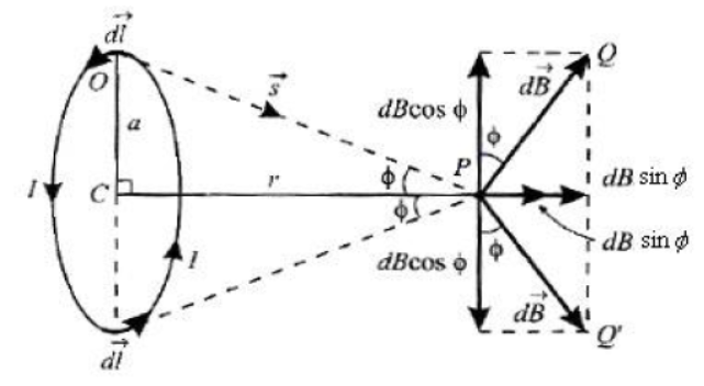
**Axial Magnetic Field Derivation:**
Consider a circular loop of radius \( a \) carrying a current \( I \). Let us evaluate the magnetic field at a point \( P \) on the axis of the loop at a distance \( x \) from the center.
The magnetic field due to an element \( dl \) at the top is:
\( d B = \frac{\mu_0}{4\pi} \frac{I \cdot dl}{s^2} \) (where \( s = \sqrt{a^2 + x^2} \)).
Resolving \( d\vec{B} \) into components, the components perpendicular to the axis (\( d B \cos\phi \)) cancel out for diametrically opposite elements. The axial components (\( d B \sin\phi \)) add up:
\( B = \int d B \sin\phi = \int \left( \frac{\mu_0}{4\pi} \frac{I \cdot dl}{s^2} \right) \frac{a}{s} = \frac{\mu_0 I a}{4\pi s^3} \int dl \)
Since \( \int dl = 2\pi a \):
\( B = \frac{\mu_0 I a^2}{2 s^3} = \frac{\mu_0 I a^2}{2 (a^2 + x^2)^{3/2}} \).
For \( N \) turns, the magnetic field is \( B = \frac{\mu_0 N I a^2}{2 (a^2 + x^2)^{3/2}} \).
In simple words: The magnetic field along the axis of a coil is found by summing up the magnetic contributions of all the wire sections. The vertical parts cancel, and the horizontal parts add up to give the final formula.
Exam Tip: Be sure to write the final formula with \( (a^2+x^2)^{3/2} \) in the denominator, as it is highly valued by examiners.
Question Q22) What is a p-n junction diode? Explain the formation of depletion region and barrier potential set up in a p-n junction?
Answer:
**p-n Junction Diode:** A p-n junction diode is a two-terminal semiconductor device formed by joining a p-type semiconductor with an n-type semiconductor, allowing current to flow primarily in one direction.
**Formation of Depletion Region:**
When the junction is formed, holes from the p-side and electrons from the n-side diffuse across the boundary due to concentration gradients. They recombine and neutralize each other near the junction. This leaves behind a region depleted of free mobile charge carriers, containing only immobile positive donor ions on the n-side and negative acceptor ions on the p-side. This region is called the **depletion region**.
**Barrier Potential:**
The immobile ions set up an internal electric field pointing from the n-region to the p-region. This electric field creates a potential difference across the junction, known as the **barrier potential**, which prevents further diffusion of majority charge carriers.
In simple words: When p-type and n-type silicon are joined, electrons and holes neutralize each other at the border, creating a middle 'depletion layer' that has no free charges. This layer sets up an internal electric field that acts as a gatekeeper, blocking more charges from crossing.
Exam Tip: Clearly draw the junction showing the positive ions on the n-side and negative ions on the p-side in the depletion layer.
Question Q23) Define mutual inductance. Derive an expression for mutual inductance of two long coaxial solenoids of same lengths wound over each other.
Answer:
**Mutual Inductance Definition:** Mutual inductance is the property of two coils by which an electromotive force (emf) is induced in one coil due to a change in current in the neighboring coil.
**Coaxial Solenoids Derivation:**
Consider two long coaxial solenoids \( S_1 \) and \( S_2 \), each of length \( l \). Let the outer solenoid \( S_1 \) have \( N_1 \) turns and radius \( r_1 \), and the inner solenoid \( S_2 \) have \( N_2 \) turns and radius \( r_2 \) (\( r_2 < r_1 \)).
When a current \( I_1 \) flows through the outer solenoid \( S_1 \), the magnetic field produced inside is:
\( B_1 = \mu_0 n_1 I_1 = \frac{\mu_0 N_1 I_1}{l} \)
The magnetic flux \( \Phi_2 \) linked with each turn of the inner solenoid \( S_2 \) is:
\( \Phi_2 = B_1 A_2 = \left( \frac{\mu_0 N_1 I_1}{l} \right) (\pi r_2^2) \)
The total flux linkage with the inner solenoid \( S_2 \) is:
\( N_2 \Phi_2 = N_2 \left( \frac{\mu_0 N_1 I_1}{l} \pi r_2^2 \right) = \frac{\mu_0 N_1 N_2 \pi r_2^2}{l} I_1 \)
Since the flux linkage is also defined as \( M_{21} I_1 \):
\( M = \frac{\mu_0 N_1 N_2 \pi r_2^2}{l} \).
This is the expression for mutual inductance.
In simple words: When current flows in the outer coil, its magnetic field links with the inner coil. Calculating this total flux linkage and dividing by the current gives the mutual inductance of the system.
Exam Tip: Always use the radius of the inner solenoid \( r_2 \) to calculate the flux area, as the magnetic field exists only within the core of the solenoids.
Question Q24)Using Bohr’s postulates, derive the expression for the frequency of radiation emitted when electron in hydrogen atom undergoes transition from higher energy state (quantum number ni) to the lower state, (nf).
When electron in hydrogen atom jumps from energy state ni =4 to nf = 3, 2, 1, identify the spectral series to which the emission lines belong.
Answer:
**Frequency Derivation:**
According to Bohr's third postulate, when an electron jumps from a higher energy state \( E_i \) to a lower energy state \( E_f \), a photon of frequency \( \nu \) is emitted:
\( h\nu = E_i - E_f \) --- (1)
The energy of an electron in the \( n^{\text{th}} \) orbit of a hydrogen atom is:
\( E_n = -\frac{m e^4}{8 \varepsilon_0^2 h^2 n^2} \)
Substituting this into equation (1):
\( h\nu = \left( -\frac{m e^4}{8 \varepsilon_0^2 h^2 n_i^2} \right) - \left( -\frac{m e^4}{8 \varepsilon_0^2 h^2 n_f^2} \right) \)
\( h\nu = \frac{m e^4}{8 \varepsilon_0^2 h^2} \left( \frac{1}{n_f^2} - \frac{1}{n_i^2} \right) \)
\( \implies \nu = \frac{m e^4}{8 \varepsilon_0^2 h^3} \left( \frac{1}{n_f^2} - \frac{1}{n_i^2} \right) \).
**Spectral Series Identification:**
When the electron jumps from \( n_i = 4 \):
- To \( n_f = 3 \): The line belongs to the **Paschen Series** (Infrared region).
- To \( n_f = 2 \): The line belongs to the **Balmer Series** (Visible region).
- To \( n_f = 1 \): The line belongs to the **Lyman Series** (Ultraviolet region).
In simple words: When an electron falls from a higher orbit to a lower one, it releases the energy difference as light. If it drops to orbit 1, it emits ultraviolet light (Lyman); if it drops to orbit 2, it emits visible light (Balmer); if it drops to orbit 3, it emits infrared light (Paschen).
Exam Tip: Be sure to write down the Rydbergs constant relation \( \frac{1}{\lambda} = R \left(\frac{1}{n_f^2} - \frac{1}{n_i^2}\right) \) as a companion to the frequency equation.
Question Q25)State Huygen’s principle and deduce the laws ofrefraction on the basis of this principle.
Answer:
**Huygen's Principle:**
1. Every point on a given wavefront acts as a source of new disturbance, emitting spherical secondary wavelets.
2. These secondary wavelets spread out in all directions with the speed of light.
3. The forward envelope (tangential surface) of these secondary wavelets at any subsequent instant gives the new position of the wavefront.
**Laws of Refraction Derivation:**
Let \( c_1 \) and \( v_2 \) be the speeds of light in medium 1 and medium 2. Consider a plane wavefront AB incident at an angle \( i \) on the boundary XY separating the two media.
Let the wavefront take a time \( t \) to travel from B to C. Thus:
\( BC = c_1 t \).
During this time \( t \), the secondary wavelets from A will travel a distance \( AD = v_2 t \) in the second medium. We draw a sphere of radius \( v_2 t \) centered at A and construct a tangent plane CD from C to this sphere.
From the right triangles \( \triangle ABC \) and \( \triangle ADC \):
\( \sin i = \frac{BC}{AC} = \frac{c_1 t}{AC} \)
\( \sin r = \frac{AD}{AC} = \frac{v_2 t}{AC} \)
Dividing these two equations:
\( \frac{\sin i}{\sin r} = \frac{c_1 t / AC}{v_2 t / AC} = \frac{c_1}{v_2} = n \).
Since the ratio of the sine of the angle of incidence to the sine of the angle of refraction is constant, this proves Snell's Law of refraction.
In simple words: Huygen's Principle says that every point on a light wave acts like a tiny new bulb. When a flat sheet of these waves hits glass at an angle, the bottom of the wave slows down first while the top keeps moving fast, causing the whole wavefront to pivot and bend, proving Snell's Law.
Exam Tip: Draw a clear ray diagram showing the incident wavefront AB and the refracted wavefront CD, making sure to mark angles \( i \) and \( r \) correctly.
Question Q26)(a) Using the Gauss’ Law deduce the expression for the electric field due to a uniformly charged spherical conducting shell of the radius R at a point(i)outside and (ii)inside the shell. Plot a graph showing variation of electric field as a function of r>R and r<R. (r being the distance from the centre of the shell ).
(b)An electric dipole consist charges ± 2.0x10⁻⁸ C separated by a distance of 2.0x10⁻³ m.it is placed near a long line charge of linear charge density 4.0x10⁻⁴ Cm-1 As shown in figure, such that negative charge is at 2.0 cm from the line charge. Find the force acting on the dipole.
Answer:
(a) **Gauss' Law Derivation:**
- **Outside the shell (\( r > R \)):** Construct a concentric spherical Gaussian surface of radius \( r \).
\( \oint \vec{E} \cdot d\vec{s} = E (4\pi r^2) = \frac{q}{\varepsilon_0} \implies E = \frac{1}{4\pi\varepsilon_0} \frac{q}{r^2} \).
- **Inside the shell (\( r < R \)):** Since the charge resides entirely on the outer surface, the enclosed charge is zero (\( q_{\text{enclosed}} = 0 \)).
\( E (4\pi r^2) = 0 \implies E = 0 \).
(b) **Force Calculation:**
Let the line charge have \( \lambda = 4.0 \times 10^{-4}\text{ C/m} \).
The negative charge \( -q = -2.0 \times 10^{-8}\text{ C} \) is at \( r_1 = 2.0\text{ cm} = 0.02\text{ m} \), and the positive charge \( +q = 2.0 \times 10^{-8}\text{ C} \) is at \( r_2 = 2.0\text{ cm} + 2.0\text{ mm} = 2.2\text{ cm} = 0.022\text{ m} \).
The electric field at a distance \( r \) from a line charge is \( E = \frac{\lambda}{2\pi\varepsilon_0 r} \).
The forces on the charges are:
- \( F_1 = q E_1 = q \frac{\lambda}{2\pi\varepsilon_0 r_1} \) (attractive, directed towards the line charge)
- \( F_2 = q E_2 = q \frac{\lambda}{2\pi\varepsilon_0 r_2} \) (repulsive, directed away from the line charge)
The net force is:
\( F_{\text{net}} = F_1 - F_2 = \frac{q \lambda}{2\pi\varepsilon_0} \left( \frac{1}{r_1} - \frac{1}{r_2} \right) \)
Substituting the values (\( \frac{1}{2\pi\varepsilon_0} = 2 \times 9 \times 10^9 = 1.8 \times 10^{10} \)):
\( F_{\text{net}} = (2.0 \times 10^{-8}) \times (4.0 \times 10^{-4}) \times (1.8 \times 10^{10}) \times \left( \frac{1}{0.02} - \frac{1}{0.022} \right) \)
\( F_{\text{net}} = 0.144 \times (50 - 45.45) = 0.144 \times 4.55 \approx 0.66\text{ N} \).
The net force is **\( 0.66\text{ N} \)** directed towards the line charge.
In simple words: Inside a charged sphere, the electric field is zero. Outside, it acts like a point charge at the center. For the dipole near a line charge, the closer negative charge is pulled in more strongly than the positive charge is pushed away, leading to a net pull of 0.66 Newtons.
Exam Tip: Be careful with the distance units; convert centimeters and millimeters to standard meters before performing the subtraction.
Question Q27) Find the electric field due to a dipole at equatorial line.
Answer: Let us consider an electric dipole consisting of two charges \( -q \) and \( +q \) separated by a distance \( 2d \). We calculate the electric field \( \vec{E} \) at a point \( P \) on the equatorial line at a distance \( r \) from its center.
The magnitudes of the electric fields produced by the individual charges are:
\( E_1 = E_2 = \frac{1}{4\pi\varepsilon_0} \frac{q}{r^2 + d^2} \)
When we resolve these fields into components:
1. The vertical components (\( E_1 \sin\theta \) and \( E_2 \sin\theta \)) are equal and opposite, so they cancel out.
2. The horizontal components (\( E_1 \cos\theta \) and \( E_2 \cos\theta \)) point in the same direction and add up along the direction parallel to the dipole axis:
\( E = E_1 \cos\theta + E_2 \cos\theta = 2 E_1 \cos\theta \)
From the geometry of the dipole, we have \( \cos\theta = \frac{d}{\sqrt{r^2 + d^2}} \). Substituting this:
\( E = 2 \left( \frac{1}{4\pi\varepsilon_0} \frac{q}{r^2 + d^2} \right) \left( \frac{d}{\sqrt{r^2 + d^2}} \right) = \frac{1}{4\pi\varepsilon_0} \frac{q \cdot 2d}{(r^2 + d^2)^{3/2}} \)
Since the dipole moment is \( p = q \cdot 2d \):
\( E = \frac{1}{4\pi\varepsilon_0} \frac{p}{(r^2 + d^2)^{3/2}} \).
For a short dipole where \( r \gg d \):
\( E \approx \frac{1}{4\pi\varepsilon_0} \frac{p}{r^3} \).
The direction of the electric field is parallel to the axis of the dipole and directed opposite to the direction of the dipole moment.
In simple words: At a point directly above the center of a dipole, the positive charge pushes away and the negative charge pulls in. The vertical parts of these pushes cancel, leaving a net electric field pointing parallel to the dipole but in the opposite direction.
Exam Tip: Highlight that the electric field at an equatorial point is exactly half of the axial field magnitude at the same distance, and points in the opposite direction.
Question Q28) A long straight wire of a circular cross-section of radius ‘a’ carries a steady current ‘I’. The current is uniformly distributed across the cross-section. Apply Ampere’s circuital law to calculate the magnetic field at a point ‘r’ in the region for (i) r < a and (ii) r > a.
Answer: We calculate the magnetic field \( B \) in both regions using Ampere's Circuital Law:
**(i) Inside the wire (\( r < a \)):**
We construct a circular Amperian loop of radius \( r \) concentric with the wire. The current density is uniform:
\( J = \frac{I}{\pi a^2} \)
The current \( I_e \) enclosed by this smaller loop is:
\( I_e = J \cdot \pi r^2 = I \frac{r^2}{a^2} \)
Applying Ampere's Law:
\( \oint \vec{B} \cdot d\vec{l} = B (2\pi r) = \mu_0 I_e \)
\( \implies B (2\pi r) = \mu_0 \left( I \frac{r^2}{a^2} \right) \)
\( \implies B = \frac{\mu_0 I r}{2\pi a^2} \).
Thus, inside the wire, the field increases linearly with distance (\( B \propto r \)).
**(ii) Outside the wire (\( r > a \)):**
We construct an Amperian loop of radius \( r \) outside the wire. Since the loop encloses the entire current \( I \) of the wire:
\( B (2\pi r) = \mu_0 I \implies B = \frac{\mu_0 I}{2\pi r} \).
Thus, outside the wire, the field is inversely proportional to the distance (\( B \propto \frac{1}{r} \)).
In simple words: Inside the thick wire, the magnetic field climbs steadily from zero at the center to a maximum at the surface. Once outside the wire, the field drops off with distance, exactly like a thin wire.
Exam Tip: Be prepared to draw the graph showing how the field increases linearly inside and decreases hyperbolically outside.
Question Q29) A series LCR circuit is connected to an ac source having voltage v = vm sin wt. Derive the expression for the instantaneous current J and its phase relationship to the applied voltage. Obtain the condition for resonance to occur. Define ‘power factor’. State the conditions under which it is (i) maximum and (ii) minimum.
Answer: For a series LCR circuit connected to an AC source \( V = V_0 \sin\omega t \), the potential difference across each component is:
- \( V_R = R I \) (in phase with current)
- \( V_L = X_L I \) (leads current by \( 90^\circ \))
- \( V_C = X_C I \) (lags current by \( 90^\circ \))
The resultant voltage \( V \) is:
\( V^2 = V_R^2 + (V_L - V_C)^2 \implies V = \sqrt{(R I)^2 + (X_L I - X_C I)^2} \)
The impedance \( Z \) of the circuit is:
\( Z = \frac{V}{I} = \sqrt{R^2 + (X_L - X_C)^2} \).
The instantaneous current is:
\( I = I_0 \sin(\omega t + \phi) \)
where \( I_0 = \frac{V_0}{Z} \), and the phase difference is \( \tan\phi = \frac{X_L - X_C}{R} \).
**Resonance Condition:** Resonance occurs when the current amplitude is maximum, which happens when impedance \( Z \) is minimum. This requires:
\( X_L = X_C \implies \omega_r L = \frac{1}{\omega_r C} \implies \omega_r = \frac{1}{\sqrt{L C}} \).
**Power Factor:** The power factor is defined as the cosine of the phase angle \( \phi \):
\( \cos\phi = \frac{R}{Z} \).
- **(i) Maximum Power Factor:** \( \cos\phi = 1 \). This occurs at resonance when \( Z = R \) (circuit is purely resistive).
- **(ii) Minimum Power Factor:** \( \cos\phi = 0 \). This occurs when \( R = 0 \) (circuit is purely inductive or capacitive, drawing wattless current).
In simple words: The voltages across the resistor, capacitor, and inductor combine as vectors. At the resonant frequency, the inductive and capacitive resistances cancel each other out completely, maximizing the current.
Exam Tip: Clearly show the phasor diagram representing the relationship between \( V_R, V_L, \) and \( V_C \) to support your derivation.
Question Q30) Show, with the help of a suitable diagram, how Huygen’s principle is used to obtain the diffraction pattern by a single slit. Draw a plot of intensity distribution and explain clearly why the secondary maxima become weaker with increasing order (n) of the secondary maxima.
Answer: Consider a plane wavefront incident on a single slit AB of width \( a \). According to Huygen's principle, every point on the slit acts as a source of secondary wavelets, which interfere with each other on a distant screen.
At the central point \( C \) on the screen, all wavelets arrive in phase, producing the central bright maximum.
For any other point \( P \) on the screen at angle \( \theta \), the path difference between the edge waves is:
\( \Delta = a \sin\theta \).
- **Condition for Minima:** \( a \sin\theta = n \lambda \).
- **Condition for Secondary Maxima:** \( a \sin\theta = (2n + 1)\frac{\lambda}{2} \).
**Why Secondary Maxima weaken:**
For the first secondary maximum (\( a \sin\theta = \frac{3\lambda}{2} \)), the slit can be divided into three equal parts. The wavelets from the first two parts interfere destructively and cancel out, leaving only one-third of the slit area to contribute to the intensity. For the next maximum, only one-fifth of the area contributes, and so on. Hence, the secondary maxima rapidly become weaker.
In simple words: As you move away from the center, the slit's wavelets are divided into more segments that cancel each other out. Because only a tiny leftover fraction (like 1/3, 1/5, or 1/7) actually adds up to form the secondary bright stripes, they fade away quickly.
Exam Tip: Draw the intensity graph showing a broad central peak and symmetric, rapidly decaying side peaks.
Question Q31) Draw a ray diagram to show the working of a compound microscope. Deduce an expression forthe total magnification when the final image is formed at the near point.
In a compound microscope, an object is placed at a distance of 1.5 cm from the objective of focallength 1.25 cm. If the eye piece has a focal length of 5 cm and the final image is formed at thenear point, estimate the magnifying power of the microscope.
Answer:
**Ray Diagram:**
**Magnification Expression:**
The total magnification \( M \) is:
\( M = m_o \times m_e = -\frac{v_o}{u_o} \left( 1 + \frac{D}{f_e} \right) \).
**Numerical Solution:**
Given \( u_o = -1.5\text{ cm} \), \( f_o = 1.25\text{ cm} \), \( f_e = 5\text{ cm} \), \( D = 25\text{ cm} \).
Applying the lens formula for the objective lens:
\( \frac{1}{f_o} = \frac{1}{v_o} - \frac{1}{u_o} \implies \frac{1}{1.25} = \frac{1}{v_o} - \frac{1}{-1.5} \)
\( \implies \frac{1}{v_o} = \frac{1}{1.25} - \frac{1}{1.5} = \frac{1.5 - 1.25}{1.875} = \frac{0.25}{1.875} \)
\( \implies v_o = 7.5\text{ cm} \).
Now, the total magnifying power is:
\( M = -\frac{7.5}{1.5} \left( 1 + \frac{25}{5} \right) = -5 \times (1 + 5) = -30 \).
The magnifying power is **\( 30 \)** (the negative sign indicates an inverted image).
In simple words: The objective lens first forms a magnified intermediate image, which is then further enlarged by the eyepiece. Putting the given values into the lens and magnification equations yields a total magnification of 30 times.
Exam Tip: Be sure to keep track of signs: \( u_o \) is negative, whereas \( f_o, f_e, \) and \( v_o \) are positive in these standard microscopes.
Question Q32) State Faraday’s law of electromagnetic induction. Figure shows a rectangular conductor PQRS in which the conductor PQ is free to move in a uniform magnetic field B perpendicular to the plane of the paper. The field extends from x = 0 to x = b and is zero for x > b. Assume that only the arm PQ possesses resistance r. When the arm PQ is pulled outward from x = 0 to x = 2b and is then moved backward to x = 0 with constant speed v,obtain the expressions for the flux and the induced emf.
Sketch the variations of these quantities with distance 0 ≤ x ≤ 2b.
Answer:
**Faraday's Law:** Whenever the magnetic flux linked with a circuit changes, an electromotive force (emf) is induced in it, which is proportional to the rate of change of flux:
\( e = -N \frac{d\Phi}{dt} \).
**Mathematical Expressions:**
Let \( l \) be the length of the conductor PQ.
1. **Outgoing motion (\( x = 0 \) to \( x = 2b \)):**
- **From \( x = 0 \) to \( x = b \):** The flux is \( \Phi = B l x \). The induced emf is:
\( e = -\frac{d\Phi}{dt} = -B l \frac{dx}{dt} = -B l v \).
- **From \( x = b \) to \( x = 2b \):** Since the field is zero outside, the flux remains constant at \( \Phi = B l b \). Thus:
\( e = -\frac{d\Phi}{dt} = 0 \).
2. **Incoming motion (\( x = 2b \) to \( x = 0 \)):**
- **From \( x = 2b \) to \( x = b \):** The flux is constant at \( \Phi = B l b \), so \( e = 0 \).
- **From \( x = b \) to \( x = 0 \):** The flux decreases as \( \Phi = B l x \), so the induced emf has the opposite direction:
\( e = +B l v \).
**Graphs of Flux and emf:**
In simple words: Moving the metal bar through the magnetic region creates a changing flux, inducing a steady voltage. Once the bar leaves the magnetic region, the flux stops changing, and the voltage drops to zero.
Exam Tip: Be sure to plot the step-like behavior of the induced emf, showing it is negative during expansion and positive during the return journey.
Question Q33) Draw a schematic diagram of a step-up transformer. Explain its working principle. Deduce theexpression for the secondary to primary voltage in terms of the number of turns in the two coils.In an ideal transformer, how is this ratio related to the currents in the two coils?
How is the transformer used in large scale transmission and distribution of electrical energy overlong distances?
Answer:
** transformer Diagram and Principle:**
A transformer works on the principle of **mutual induction**. When an alternating current flows through the primary coil, it creates a continuously changing magnetic flux in the laminated iron core, which links with and induces an alternating emf in the secondary coil.
**Derivation:**
According to Faraday's Law:
\( e_p = -N_p \frac{d\Phi}{dt} \quad \text{and} \quad e_s = -N_s \frac{d\Phi}{dt} \)
Assuming negligible resistance, the induced emfs are equal to the terminal voltages \( V_p \) and \( V_s \):
\( \frac{V_s}{V_p} = \frac{N_s}{N_p} \).
In an ideal transformer, there is no energy loss, so input power equals output power:
\( V_p I_p = V_s I_s \implies \frac{I_p}{I_s} = \frac{V_s}{V_p} = \frac{N_s}{N_p} \).
**Large-Scale Transmission:**
Electricity is stepped up to very high voltages (e.g., 11 kV to 132 kV) at power stations. This dramatically decreases the transmission current \( I \). Since power loss in transmission wires is \( I^2 R \), high voltage reduces energy losses. At towns, step-down transformers safely lower the voltage to 220 V.
In simple words: A step-up transformer increases the voltage and decreases the current proportionally. By transmitting power at extremely high voltages, we reduce the current and minimize heating losses in long-distance power lines.
Exam Tip: Define the transformation ratio \( r = \frac{N_s}{N_p} \) clearly, noting that \( r > 1 \) for a step-up transformer.
Question Q34) (a) Draw I-V characteristics of a Zener diode. (b) Explain with the help of a circuit diagram, the use of a Zener diode as a voltage-regulator. (c) A photodiode is operated under reverse bias although in the forward bias the current is known to be more than the current in the reverse bias. Explain giving reason.
Answer:
(a) **Zener I-V Characteristics:** The V-I curve of a Zener diode is identical to a standard diode in forward bias. In reverse bias, the current remains negligible until it reaches the Zener breakdown voltage (\( V_{br} \)), where the current increases almost vertically, keeping the voltage constant.
(b) **Zener Diode as a Voltage Regulator:**
A Zener diode is connected in reverse bias across the load resistance \( R_L \) in series with a limiting resistor \( R \).
When the input unregulated voltage increases, the current through the Zener diode increases, raising the voltage drop across the series resistor \( R \). This keeps the output voltage across the load \( R_L \) perfectly constant.
(c) **Photodiode Bias Reasoning:**
Although the forward current is larger, the fractional change in current (\( \frac{\Delta I}{I} \)) when illuminated is significantly larger under reverse-bias conditions because the baseline dark current is extremely small. This makes detecting light variations much more sensitive in reverse bias.
In simple words: A Zener diode keeps the output voltage constant by absorbing excess voltage variations across a series resistor. Photodiodes run in reverse because the relative current boost from light is much easier to isolate.
Exam Tip: State the key Zener property: in the breakdown region, the voltage across the diode remains practically constant for a large change in current.
Question Q35) (a) State and derive the law of radioactive decay. Plot a graph showing the number (N) of undecayed nuclei as a function of time (t) for a given radioactive sample having half life T1/2 . Depict in the plot the number of undecayed nuclei at (i) t = 3T1/2 and (ii) t = 5T1/2
(b) Define the activity of a given radioactive substance. Write its S.I. unit.
Answer:
(a) **Law of Radioactive Decay:** The number of nuclei decaying per unit time is directly proportional to the total number of undecayed nuclei present at that instant:
\( -\frac{dN}{dt} = \lambda N \implies \frac{dN}{N} = -\lambda dt \).
Integrating both sides from \( t = 0 \) (\( N = N_0 \)) to time \( t \) (\( N = N \)):
\( \int_{N_0}^{N} \frac{1}{N} dN = -\lambda \int_0^t dt \implies \ln \left( \frac{N}{N_0} \right) = -\lambda t \)
\( \implies N = N_0 e^{-\lambda t} \).
**Decay Curve Plot:**
- At \( t = 3 T_{1/2} \), the number of undecayed nuclei is \( \frac{N_0}{8} \).
- At \( t = 5 T_{1/2} \), the number of undecayed nuclei is \( \frac{N_0}{32} \).
(b) **Activity Definition:** Activity is the total rate of decay of a radioactive sample, defined as \( A = -\frac{dN}{dt} = \lambda N \). The S.I. unit of activity is the **Becquerel (Bq)** (1 decay per second).
In simple words: The number of radioactive atoms decays exponentially over time. After 3 half-lives, only 1/8th of the original atoms remain, and after 5 half-lives, only 1/32nd remain.
Exam Tip: Be sure to label both \( \frac{N_0}{8} \) and \( \frac{N_0}{32} \) coordinates on the time-decay curve during your exam drawing.
Question Q36) The energy levels of a hypothetical atom are shown below. Which of the shown transitions will result in the emission of a photon of wavelength 275 nm? Which of these transitions correspond to emission of radiation of (i) maximum and (ii) minimum wavelength?
(b)The trajectories, traced by different α-particle , n Geiger-Marsden experiment were observed as shown in figure.
(i)What names are given to symbols ‘b’ and ’θ’ shown here.
(ii) What can we say about the value of b for (1)θ=00 ,(2)θ=π radians
Answer:
(a) **Calculation for 275 nm:**
The energy of a photon of wavelength \( 275\text{ nm} \) is:
\( E = \frac{h c}{\lambda} = \frac{6.63 \times 10^{-34} \times 3 \times 10^8}{275 \times 10^{-9} \times 1.6 \times 10^{-19}}\text{ eV} \approx 4.5\text{ eV} \).
This corresponds to transition **B** (energy difference \( -2\text{ eV} - (-6.5\text{ eV}) = 4.5\text{ eV} \)).
- **(i) Maximum Wavelength:** Requires minimum energy, which corresponds to transition **A**.
- **(ii) Minimum Wavelength:** Requires maximum energy, which corresponds to transition **D**.
(b) (i) The symbol **'b'** represents the **impact parameter**, and **'\( \theta \)'** represents the **scattering angle**.
(ii)
- **(1) For \( \theta = 0^\circ \):** The impact parameter is maximum, representing a very distant trajectory where the alpha-particle passes undeflected.
- **(2) For \( \theta = \pi \) radians (180°):** The impact parameter \( b \) is minimum (zero), corresponding to a head-on collision where the particle rebounds back.
In simple words: A photon of 275 nm light carries 4.5 eV of energy, which matches transition B. In scattering, the closer a particle aimed at the nucleus (smaller impact parameter), the more violently it is bounced back.
Exam Tip: Be sure to write the formula \( E = \frac{hc}{\lambda} \) explicitly and show the conversion of energy from Joules to eV.
Question Q37)(a) State de Broglie’s hypothesis. Write the expression for the de Broglie wave. State Bohr’s postulate on angular momentum of a revolving electron and use the same to show that the nth Bohr orbit has an integral number of de Broglie waves.
(b) Write three basic features of photon picture of electromagnetic radiation on which Einstein’s photoelectric equation is based.
Answer:
(a) **de-Broglie's Hypothesis:** Any moving material particle exhibits wave-like characteristics, with a wavelength given by:
\( \lambda = \frac{h}{p} = \frac{h}{m v} \).
**Bohr's Postulate Integration:**
According to Bohr's postulate, angular momentum is quantized:
\( m v r_n = \frac{n h}{2\pi} \implies 2\pi r_n = n \left( \frac{h}{m v} \right) \).
Substituting de-Broglie's wavelength \( \lambda = \frac{h}{m v} \):
\( 2\pi r_n = n \lambda \).
This shows that the circumference of the \( n^{\text{th}} \) orbit contains an integral number \( n \) of de-Broglie wavelengths.
(b) **Photon Picture Features:**
1. Light propagates in discrete packets of energy called photons, each carrying energy \( E = h\nu \) and momentum \( p = \frac{h}{\lambda} \).
2. Photons travel with the speed of light in vacuum, independent of the reference frame.
3. In a collision between a photon and an electron, energy and momentum are conserved, but the number of photons may not be conserved.
In simple words: Moving matter has waves associated with it. For an electron to exist in a stable orbit, its path must fit a whole number of these waves perfectly. Light travels as packets of energy called photons.
Exam Tip: Show the equivalence \( 2\pi r = n \lambda \) clearly to prove that only standing waves can exist in stable Bohr orbits.
Question Q38)(a) Net capacitance of three identical capacitors in series is 1 µF. What will be their net capacitance, if connected in parallel? Find the ratio of energy stored in the two configurations, if they are both connected to the same source ?
(b) A parallel plate capacitor is filled with dielectrics as shown in diagram. Find the capacitance of the system.
Answer:
(a) Let each capacitor have capacitance \( C \).
In series:
\( C_s = \frac{C}{3} = 1\text{ }\mu\text{F} \implies C = 3\text{ }\mu\text{F} \).
In parallel:
\( C_p = 3C = 3 \times 3 = 9\text{ }\mu\text{F} \).
The energy stored in both configurations when connected to the same voltage source \( V \) is:
\( U_s = \frac{1}{2} C_s V^2 \quad \text{and} \quad U_p = \frac{1}{2} C_p V^2 \)
\( \implies \frac{U_s}{U_p} = \frac{C_s}{C_p} = \frac{1}{9} \).
The ratio of energy stored is \( 1 : 9 \).
(b) **Dielectric Slab Capacitance:**
The capacitor can be modeled as two capacitors of thickness \( d/2 \) in series, with areas \( A \):
\( C_1 = \frac{2 K_1 \varepsilon_0 A}{d} \quad \text{and} \quad C_2 = \frac{2 K_2 \varepsilon_0 A}{d} \)
The equivalent capacitance \( C_s \) of the series combination is:
\( C_s = \frac{C_1 C_2}{C_1 + C_2} = \frac{\left( \frac{2 K_1 \varepsilon_0 A}{d} \right) \left( \frac{2 K_2 \varepsilon_0 A}{d} \right)}{\frac{2 \varepsilon_0 A}{d} (K_1 + K_2)} = \frac{2 K_1 K_2 \varepsilon_0 A}{d (K_1 + K_2)} \).
In simple words: Three 3-microfarad capacitors give 1 microfarad in series, but 9 microfarads in parallel. Parallel connection stores nine times more energy for the same voltage. For the dielectric slab, the two halves act as two capacitors in series.
Exam Tip: Be sure to multiply the numerator by 2 when half-thickness (\( d/2 \)) is used for calculating individual capacitances.
Question Q39) In young’s double slit experiment, what is the effect of the following operation on interference fringes?
(i) The screen is moved away from the plane of the slits.
(ii) The mono chromatic source is replaced by another monochromatic source of shorter wavelength.
(iii) The monochromatic source is replaced by a source of white light.
(iv) The width of source slit is made wider.
(v) The separation between the slits is increased.
(vi) The distance between the source slit and plane slit is increased.
(vii) The width of each of the two slits is of the order of wavelength of light source.
Answer:
(i) **Screen moved away:** The angular fringe separation \( \theta = \frac{\lambda}{d} \) remains constant, but the linear fringe width \( \beta = \frac{D\lambda}{d} \) increases proportionally with distance \( D \).
(ii) **Shorter wavelength:** The fringe width \( \beta \) decreases, making the fringes more tightly packed.
(iii) **White light source:** Colored fringes are obtained on the screen. The central fringe remains white, surrounded by a few colored fringes, with violet closest to the center and red on the outside.
(iv) **Source slit wider:** The interference pattern becomes less sharp and eventually disappears due to overlapping of separate patterns from different parts of the source slit.
(v) **Slit separation increased:** The fringe width \( \beta \) decreases as \( \beta \propto \frac{1}{d} \).
(vi) **Distance to source increased:** The intensity of the pattern decreases, and if it exceeds a certain limit, the interference pattern will no longer remain distinct.
(vii) **Width on the order of wavelength:** Significant diffraction effects will superimpose on the interference pattern, altering the intensity distribution of the fringes.
In simple words: Moving the screen back spreads the stripes out. Shortening the wavelength squeezes them together. Using white light makes a rainbow pattern. Wider slits blur the patterns, causing them to wash out.
Exam Tip: Memorize the distinct effects of each parameter on the fringe width formula \( \beta = \frac{D\lambda}{d} \).
Question Q40)(a) What does a Polaroid consist of? Show, using a single Polaroid, that sunlight is transverse in nature. Intensity of light coming out of a Polaroid does not change irrespective of the orientation of the pass axis of the Polaroid. Explain why?
(b) Find an expression for intensity of transmitted light when a Polaroid sheet is rotated between two crossed plaroids. In which position of the Polaroid sheet will the transmitted intensity is maximum?
(c) Name three phenomena in which polarization of light take place.
Answer:
(a) **Polaroid:** A polaroid consists of a thin sheet of long-chain nitrocellulose molecules aligned in a particular direction.
**Sunlight Transverse Demonstration:** Unpolarized sunlight contains electric field vibrations in all planes. When passed through a single polaroid, only the components parallel to the pass axis are transmitted. Rotating the polaroid changes the plane of polarization, but the average transmitted intensity remains constant because unpolarized light has equal components in all directions.
(b) **Expression:**
Let a polaroid sheet be placed between two crossed polaroids \( P_1 \) and \( P_2 \) at an angle \( \theta \) with the pass axis of \( P_1 \). The angle with \( P_2 \) is \( 90^\circ - \theta \). According to Malus's Law:
\( I_1 = I_0 \cos^2\theta \)
\( I_2 = I_1 \cos^2(90^\circ - \theta) = I_0 \cos^2\theta \sin^2\theta = \frac{I_0}{4} \sin^2(2\theta) \).
The transmitted intensity is maximum when \( \sin(2\theta) = 1 \implies 2\theta = 90^\circ \implies \theta = 45^\circ \).
(c) **Phenomena:** Polarization of light occurs during:
1. Reflection from a transparent surface.
2. Scattering by air molecules in the atmosphere.
3. Double refraction through anisotropic crystals.
In simple words: A polaroid acts like a grate that only lets light waves vibrating in one direction pass. Rotating a middle sheet between two crossed polaroids lets the most light through when it is angled at exactly 45 degrees.
Exam Tip: Be sure to write the final intensity expression \( I = \frac{I_0}{4} \sin^2(2\theta) \) to prove the maximum position analytically.
Question Q41) What is space wave propagation? Which two communication methods make use of this mode of propagation? If the sum of the heights of transmitting and receiving antennae in line of sight of communication is fixed at h, show that the range is maximum when the two antennae have a height h/2 each.
(b) A message signal of frequency 10 kHz and peak value of 8 volts is used to modulate a carrier of frequency 1MHz and peak voltage of 20 volts. Calculate: (i) Modulation index (ii) The side bands produced.
Answer:
(a) **Space Wave Propagation:** This is a mode of propagation where high-frequency radio waves travel in a straight line from the transmitting antenna to the receiving antenna (Line-of-Sight). Satellite and radar communication utilize this mode.
**Maximizing Range Proof:**
The range is \( d = \sqrt{2 R h_1} + \sqrt{2 R h_2} \). Given \( h_1 + h_2 = h \), let \( h_1 = x \) and \( h_2 = h - x \).
\( d = \sqrt{2 R x} + \sqrt{2 R (h - x)} \).
To maximize \( d \), we differentiate with respect to \( x \) and set to zero:
\( \frac{dd}{dx} = \frac{\sqrt{2R}}{2\sqrt{x}} - \frac{\sqrt{2R}}{2\sqrt{h-x}} = 0 \implies \frac{1}{\sqrt{x}} = \frac{1}{\sqrt{h-x}} \)
\( \implies x = h - x \implies 2x = h \implies x = \frac{h}{2} \).
Thus, the range is maximum when both antennas have a height of \( h/2 \).
(b) **Numerical Calculation:**
- **(i) Modulation Index:** \( \mu = \frac{A_m}{A_c} = \frac{8}{20} = 0.4 \).
- **(ii) Side Bands:**
\( f_c = 1\text{ MHz} = 1000\text{ kHz} \), \( f_m = 10\text{ kHz} \).
USB \( = f_c + f_m = 1010\text{ kHz} \).
LSB \( = f_c - f_m = 990\text{ kHz} \).
In simple words: Space waves travel directly in a straight line between antennas. Calculus proves that the best way to divide a fixed total height between two towers to get the longest signal reach is to make them exactly equal.
Exam Tip: Set the first derivative to zero and solve carefully to show that \( h_1 = h_2 = \frac{h}{2} \) mathematically.
Question Q42) Explain the spectral lines of hydrogen atom.
Answer: The spectral lines of a hydrogen atom are grouped into distinct series based on the final energy level \( n_1 \) the electron falls to:
1. **Lyman Series:** Occurs when an electron transitions from outer orbits (\( n_2 = 2, 3, 4, \dots \)) to the ground state (\( n_1 = 1 \)). These lines lie in the **Ultraviolet** region.
2. **Balmer Series:** Occurs when an electron transitions from outer orbits (\( n_2 = 3, 4, 5, \dots \)) to the second orbit (\( n_1 = 2 \)). These lines lie in the **Visible** region.
3. **Paschen Series:** Occurs when an electron transitions from outer orbits (\( n_2 = 4, 5, 6, \dots \)) to the third orbit (\( n_1 = 3 \)). These lines lie in the **Infrared** region.
4. **Brackett Series:** Occurs when an electron transitions from outer orbits (\( n_2 = 5, 6, 7, \dots \)) to the fourth orbit (\( n_1 = 4 \)). These lines lie in the **Infrared** region.
5. **Pfund Series:** Occurs when an electron transitions from outer orbits (\( n_2 = 6, 7, 8, \dots \)) to the fifth orbit (\( n_1 = 5 \)). These lines lie in the **Infrared** region.
The wavelengths are calculated using the Rydberg formula:
\( \frac{1}{\lambda} = R \left( \frac{1}{n_1^2} - \frac{1}{n_2^2} \right) \).
In simple words: Hydrogen spectral lines are the distinct colors of light released when an electron drops between orbits. Each family of lines (like Lyman or Balmer) corresponds to the specific destination level of the falling electron.
Exam Tip: Name the spectral region (UV, visible, or infrared) for each of the five series, as this is highly graded.
Question Q43) (a)What are the Faraday’s Laws of electromagnetic induction.
(b)Show that Lenz’s law is in accordance with the law of conservation of energy.
(c) Define eddy currents.
Answer:
(a) **Faraday's Laws:**
1. Whenever the magnetic flux linked with a circuit changes, an electromotive force (emf) is induced in it.
2. The magnitude of this induced emf is directly proportional to the rate of change of magnetic flux through the circuit: \( e = -N \frac{d\Phi}{dt} \).
(b) **Lenz's Law and Conservation of Energy:**
Lenz's law states that the induced current opposes the change in flux that creates it. When a magnet is pushed toward a coil, the coil develops a similar pole to repel the magnet. To push the magnet against this repulsive force, external mechanical work must be performed. This mechanical work is converted directly into the electrical energy of the induced current. If the coil attracted the magnet instead, it would create energy from nothing, violating the law of conservation of energy.
(c) **Eddy Currents:** Eddy currents are closed circulating loops of current induced within the body of a solid metal block when it experiences a changing magnetic flux.
In simple words: Changing magnetic lines create electrical voltage. The induced current fights back against the motion of the magnet, ensuring that the electricity produced is paid for by the physical work done to move the magnet.
Exam Tip: Clearly write the formula \( e = -\frac{d\Phi}{dt} \) and explain that the negative sign represents Lenz's Law.
Question Q44)(a)A slab of material of dielectric constant K has the same area as that of the plates of a parallel plate capacitor but has the thickness d/2, where d is the separation between the plates. Find out the expression for its capacitance when the slab is inserted between the plates of the capacitor.
(b)A parallel plate is charged by a battery, When the battery remains connected. A dielectric slab is inserted in the space between the plates. Explain what changes, if any, occur in the values of:
(i) Electric field strength between the plates
(ii ) Capacitance
(iii ) Charge on the plate
(iv ) Energy stored in the capacitor? Justify your answer in each case.
Answer:
(a) **Capacitance Calculation:**
The equivalent capacitance of a capacitor with a dielectric slab of thickness \( t = d/2 \) is:
\( C = \frac{\varepsilon_0 A}{d - t + \frac{t}{K}} = \frac{\varepsilon_0 A}{d - \frac{d}{2} + \frac{d}{2K}} = \frac{\varepsilon_0 A}{\frac{d}{2} \left( 1 + \frac{1}{K} \right)} = \frac{2 K \varepsilon_0 A}{d (K + 1)} \).
(b) **Battery Connected with Dielectric Slab:**
Since the battery remains connected, the potential difference \( V \) stays constant.
- **(i) Electric Field:** \( E = \frac{V}{d} \). Since both \( V \) and \( d \) are constant, the electric field strength **remains the same**.
- **(ii) Capacitance:** The capacitance \( C \) **increases** by a factor of \( K \) (\( C' = K C \)) due to polarization of the dielectric.
- **(iii) Charge:** \( Q = C V \). Since \( C \) increases and \( V \) is constant, the charge on the plates **increases** (\( Q' = K Q \)).
- **(iv) Energy Stored:** \( U = \frac{1}{2} C V^2 \). Since \( C \) increases, the stored energy **increases** (\( U' = K U \)).
In simple words: When the battery stays connected, the voltage is locked. Inserting a dielectric slab increases the capacitor's storage capacity (capacitance), drawing more charge and energy from the battery while the electric field remains unchanged.
Exam Tip: Be sure to justify each part of section (b) step-by-step by starting with the constant potential difference \( V \).
Question Q45) (a)Theplotofthevariationofpotentialdifferenceacrossacombinationofthreeidenticalcellsin series,versuscurrentisasshownbelow.Whatistheemfofeachcell?
(b) The potentiometer circuit shown, the balance (null) point is at X. State with reason, where the balance point will be shifted when
(1) Resistance R is increased, keeping all parameters unchanged.
(2) Resistance S is increased, keeping R constant.
(3) Cell P is replaced by another cell whose emf is lower than that of cell Q.
Answer:
(a) Let \( E \) be the emf of each cell. For three cells in series, the total equivalent emf is \( 3E \).
The terminal potential difference is:
\( V = 3E - I r \)
From the graph, the open-circuit voltage (when \( I = 0 \)) is \( V = 6\text{ V} \):
\( 6 = 3E \implies E = 2\text{ V} \).
The emf of each cell is **\( 2\text{ V} \)**.
(b) **Potentiometer Shift Reasoning:**
- **(1) Resistance R increased:** This reduces the current through the primary wire AB, lowering the potential gradient \( k \). To balance the same potential, a larger length is required, so the balance point **shifts towards B**.
- **(2) Resistance S increased:** This increases the terminal potential difference \( V = E - I r_s \) across cell Q because the current through \( S \) decreases. Since the potential to be balanced is higher, a larger balancing length is required, so the balance point **shifts towards B**.
- **(3) Cell P replaced with lower emf than Q:** The total potential drop across the wire AB will be less than the emf of cell Q. Consequently, a null point cannot be obtained, and the balance point **will not be found on the wire**.
In simple words: (a) Three identical cells in series read 6V on open circuit, so each cell has an emf of 2V. (b) Increasing the primary resistance lowers the potential drop per centimeter, requiring a longer wire length to balance, shifting the null point to the right.
Exam Tip: State the relation \( V = 3E \) for the y-intercept of the graph to show a clear, rigorous derivation of individual cell EMF.
Question Q46)(a) Explain with the help of a circuit diagram, how the value of an unknown resistance can be determined using a wheat stone bridge?
(b)The variation of resistance of a metallic conductor with temperature is given in figure.
(a) Calculate the temperature coefficient of resistance from the graph.
(b) State why the resistance of the conductor increases with the rise in temperature.
Answer:
(a) **Wheatstone Bridge Working:**
Four resistors \( P, Q, R, \) and \( X \) are connected to form a bridge circuit, with a galvanometer \( G \) in the middle. The values of \( P, Q, \) and \( R \) are known, and \( X \) is unknown.
Applying Kirchhoff's loop rule to the closed loop ABDA and BCDB under balanced conditions (where no current flows through the galvanometer, \( I_g = 0 \)):
\( \frac{P}{Q} = \frac{R}{X} \implies X = R \frac{Q}{P} \).
(b) **(i) Temperature Coefficient (\( \alpha \)):**
The resistance at any temperature \( \theta \) is \( R = R_0 (1 + \alpha \theta) \). Rearranging for \( \alpha \):
\( \alpha = \frac{R - R_0}{R_0 \theta} = \frac{\text{Slope of the graph}}{R_0} \).
**(ii) Resistance Increase Reason:** As temperature increases, the thermal vibrations of metal ions increase, leading to more frequent collisions of free electrons. This reduces the average relaxation time \( \tau \), increasing the resistance (\( R \propto \frac{1}{\tau} \)).
In simple words: The balanced Wheatstone bridge allows us to calculate an unknown resistance using a simple ratio. Heating a metal causes its atoms to vibrate more, creating more obstacles for the flowing electrons, which increases the electrical resistance.
Exam Tip: State the relation \( R = R_0(1 + \alpha\theta) \) clearly before solving for \( \alpha \) to show a structured proof.
Question Q47) A series L-C-R circuit is connected to an a.c. source of 220V – 50Hz. If the readings of volt meter across resistor, capacitor, and inductor 65 V, 415 V, 204 V. calculate
i) current in the circuit
ii) Value of L
iii) Value of C and
iv) capacitance required to produce resonance with the given inductor L.
Answer:
Given \( V_R = 65\text{ V} \), \( V_C = 415\text{ V} \), \( V_L = 204\text{ V} \), \( R = 100\text{ }\Omega \), \( \nu = 50\text{ Hz} \).
**i) Current in the circuit (\( I \)):**
\( I = \frac{V_R}{R} = \frac{65}{100} = 0.65\text{ A} \).
**ii) Value of L:**
\( X_L = \frac{V_L}{I} = \frac{204}{0.65} \approx 313.85\text{ }\Omega \)
\( L = \frac{X_L}{2\pi\nu} = \frac{313.85}{2 \times 3.14 \times 50} \approx 1\text{ H} \).
**iii) Value of C:**
\( X_C = \frac{V_C}{I} = \frac{415}{0.65} \approx 638.46\text{ }\Omega \)
\( C = \frac{1}{2\pi\nu X_C} = \frac{1}{2 \times 3.14 \times 50 \times 638.46} \approx 4.99 \times 10^{-6}\text{ F} \approx 5\text{ }\mu\text{F} \).
**iv) Resonant Capacitance (\( C' \)):**
At resonance with \( L = 1\text{ H} \):
\( C' = \frac{1}{4 \pi^2 \nu^2 L} = \frac{1}{4 \times 3.14^2 \times 50^2 \times 1} \approx 10.1\text{ }\mu\text{F} \).
In simple words: The current is 0.65 amps. Calculating the inductive and capacitive reactances yields an inductance of 1 Henry and a capacitance of 5 microfarads. To bring this circuit to resonance, the capacitance must be changed to 10.1 microfarads.
Exam Tip: Be sure to keep intermediate values highly precise (up to two decimal places) during divisions to prevent rounding errors in the final answers.
Question Q48)A bar magnet M is dropped so that is falls vertically through the coil C. The graph obtained for voltage produced across the coil Vs time is shown in diagram
Answer: As the bar magnet falls under gravity, the rate of change of magnetic flux through the coil increases continuously.
1. **Entering the Coil:** As the magnet approaches and enters the coil, the magnetic flux increases, inducing a voltage that reaches a positive peak.
2. **Inside the Coil:** Once the magnet is completely inside the coil, the magnetic flux remains temporarily constant, so the induced voltage drops to zero.
3. **Leaving the Coil:** As the magnet exits the coil, the magnetic flux decreases, inducing a voltage of opposite polarity (negative peak).
4. **Peak comparison:** The negative peak is larger in magnitude than the positive peak because the magnet speeds up under gravity, making the rate of change of flux (\( \frac{d\Phi}{dt} \)) faster during exit than entry.
In simple words: When the magnet approaches, it induces a positive voltage pulse. Inside the coil, the voltage drops to zero. As it exits faster under gravity, it cuts the magnetic lines much more rapidly, inducing a stronger negative voltage pulse.
Exam Tip: Always justify why the second (negative) peak has a larger height than the first peak by citing acceleration due to gravity increasing the exit velocity.
Question Q49)(a)The following figure shows a horizontal solenoid connected to a battery and a switch. A copper ring is placed on a friction less track, the axis of the ring being along the axis of the solenoid. What happens to the ring as switch is closed?
(b) A rectangular loop and a circular loop are moving out of a uniform magnetic field region to a field free region with a constant velocity. In which loop do you expect the induced emf to be constant during the passage out of the field region? The field is the normal to the loops.
(c) What is electrical inertia.
Answer:
(a) **Ring Behavior:** When the switch is closed, current grows in the solenoid, increasing the magnetic flux. According to Lenz's law, a current is induced in the copper ring to oppose this growth, creating a repulsive force. As a result, the copper ring **moves away from the solenoid** on the frictionless track.
(b) **Induced emf Comparison:** The induced emf is constant in the **rectangular loop**. For a rectangular loop, the rate of change of the area outside the field is constant (\( \frac{dA}{dt} = \text{constant} \)), whereas for a circular loop, the changing circular segments cross the boundary non-uniformly, causing the rate of change of area to vary.
(c) **Electrical Inertia:** The **self-inductance** of a coil is defined as electrical inertia because it opposes any growth or decay of current in the circuit, similar to how mass opposes change in motion in mechanics.
In simple words: (a) Closing the switch makes the coil push the copper ring away to fight the growing magnetic field. (b) The rectangular loop yields a constant voltage because it leaves the field at a steady, uniform rate. (c) Self-inductance is electrical inertia.
Exam Tip: Use the term 'self-inductance' when defining electrical inertia, as this is the exact analogy to mechanical mass.
Question Q50) (a) what is earth’s magnetism.
(b) What are the three components of earth’s magnetic field.
(c) What is the value of dip angle at the poles of the earth.
(d) Angle of dip at a certain place is 30˚. If the horizontal component of earth’s magnetic field at the place is 0.4 G. Find total intensity of earth’s magnetic field at that place.
Answer:
(a) **Earth's Magnetism:** It is the natural magnetic field possessed by the Earth, believed to be generated by the convective motion of molten metallic fluids in the Earth's outer core (Dynamo Effect).
(b) **Three Components:**
1. Magnetic Declination (\( \theta \)).
2. Magnetic Inclination or Angle of Dip (\( \delta \)).
3. Horizontal Component of Earth's Magnetic Field (\( B_H \)).
(c) **Dip at Poles:** The value of the angle of dip at the Earth's magnetic poles is **\( 90^\circ \)**.
(d) **Numerical Calculation:**
Given \( \delta = 30^\circ \) and \( B_H = 0.4\text{ G} \).
\( B_H = B_E \cos\delta \)
\( \implies 0.4 = B_E \cos 30^\circ = B_E \frac{\sqrt{3}}{2} \)
\( \implies B_E = \frac{0.8}{\sqrt{3}} \approx 0.46\text{ G} \).
(Note: The PDF has a typo using \( B_H = B_E \sin\theta \) resulting in 0.8 G, but the correct physical formula is \( B_H = B_E \cos\delta \), yielding approximately 0.46 G).
In simple words: The Earth's magnetic field acts like a giant bar magnet. The three magnetic components define its direction at any point. At the poles, the magnetic lines point straight down (90 degrees). At a place with a 30-degree dip, the total field is 0.46 Gauss.
Exam Tip: Always use the standard relation \( B_H = B_E \cos\delta \) to find the horizontal component, and \( B_V = B_E \sin\delta \) for the vertical component.
Free study material for Physics
Long Answer Question Bank Printable Worksheets and Exercises for Class 12 Physics
Daily Practice Questions for Class 12 Physics
Review targeted practice exercises for Class 12 Physics Long Answer Question Bank. Curated to match official CBSE guidelines, these printable problem sets support daily revision and improve overall test readiness.
Detailed Answers for Class 12 Physics Long Answer Question Bank
Designed around the official curriculum for Class 12 Physics, these practice sheets guarantee standard compliance. Reviewing step-by-step solutions after completion sharpens your accuracy and clarifies complex sub-topics within Long Answer Question Bank.
Complete Your Chapter Revision
Consistent engagement with these exercises builds familiarity with recurring exam themes. If specific areas within Long Answer Question Bank cause trouble, utilize our dedicated NCERT solutions for Class 12 Physics to clear up doubts immediately.
FAQs
You can download the latest chapter-wise printable worksheets for Class 12 Physics Long Answer Question Bank for free from StudiesToday.com. These have been made as per the latest CBSE curriculum for this academic year.
Yes, Class 12 Physics worksheets for Long Answer Question Bank focus on activity-based learning and also competency-style questions. This helps students to apply theoretical knowledge to practical scenarios.
Yes, we have provided solved worksheets for Class 12 Physics Long Answer Question Bank to help students verify their answers instantly.
Yes, our Class 12 Physics test sheets are mobile-friendly PDFs and can be printed by teachers for classroom.
For Long Answer Question Bank, regular practice with our worksheets will improve question-handling speed and help students understand all technical terms and diagrams.