

Official Class 12 Physics Worksheets: Short Answer Question Bank
Explore structured practice materials through the CBSE Class 12 Physics Short Answer Question Bank Worksheet Set 03. Tailored for Class 12 learners, utilizing these Physics worksheets ensures thorough preparation and strengthens problem-solving accuracy before final school evaluations.
Solved Practice Worksheets for Physics
View or download the dedicated CBSE Class 12 Physics Short Answer Question Bank Worksheet Set 03 resource below. Engaging with these practice papers under focused study conditions ensures continuous academic progress and mastery of the 2026-27 curriculum for Short Answer Question Bank.
CBSE Class 12 Physics Short Answer Question Bank (3). Students can download these worksheets and practice them. This will help them to get better marks in examinations. Also refer to other worksheets for the same chapter and other subjects too. Use them for better understanding of the subjects.
Section A
Q1. A force ‘F’ is acting between two charges placed some distances apart in vacuum. If a brass rod is placed between these two charges, how does the force change?
Q2.A certain potential difference ‘V’ is applied across a conductor. If another conductor is connected in parallel with it, what happens to the drift velocity?
Q3. An electron and a proton, having equal momentum, enter a uniform magnetic field at right angles to the field lines. What will be the ratio of curvature of their trajectories?
Q4.The electric current flowing in a wire in the direction B to A is decreasing. What is thedirection of induced current in the metallic loop kept above the wire as shown in Figure1?
Section A ( 1 Mark )
Question. A force ‘F’ is acting between two charges placed some distances apart in vacuum. If a brass rod is placed between these two charges, how does the force change?
Answer: The force between two charges in a medium of dielectric constant \( K \) is given by \( F' = \frac{F}{K} \). Since brass is a metal (conductor), its dielectric constant \( K \) is infinitely large (\( K = \infty \)). Therefore, the force between the two charges will become zero (\( F' = \frac{F}{\infty} = 0 \)).
Question. A certain potential difference ‘V’ is applied across a conductor. If another conductor is connected in parallel with it, what happens to the drift velocity?
Answer: The drift velocity of electrons in a conductor is given by \( v_d = \frac{e V \tau}{m L} \). When another conductor is connected in parallel across the same potential difference, the voltage \( V \) across the first conductor remains unchanged. Since the length \( L \) and temperature-dependent relaxation time \( \tau \) of the original conductor do not change, its drift velocity remains constant.
Question. An electron and a proton, having equal momentum, enter a uniform magnetic field at right angles to the field lines. What will be the ratio of curvature of their trajectories?
Answer: The radius of curvature of the circular trajectory of a charged particle in a magnetic field is given by \( r = \frac{p}{qB} \). Since both particles have equal momentum \( p \), enter the same magnetic field \( B \), and carry the same magnitude of charge \( q = e \), the radius of curvature for both trajectories will be equal (\( r_e = r_p \)). The ratio of curvature (which is \( 1/r \)) will be \( 1 : 1 \).
Question. The electric current flowing in a wire in the direction B to A is decreasing. What is the direction of induced current in the metallic loop kept above the wire as shown in Figure 1?
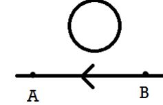
Answer: According to the right-hand grip rule, the magnetic field produced by the current flowing from right to left (B to A) in the region above the wire is directed perpendicularly out of the page. As the current decreases, this magnetic flux pointing out of the page decreases. By Lenz's law, the induced current in the metallic loop will flow in a counter-clockwise (anticlockwise) direction to oppose this decrease by producing its own magnetic field out of the page.
Question. Arrange the following in the descending order of wavelengths: Gamma Rays, Infrared Rays, Microwaves, and Radio Waves.
Answer: The descending order of wavelengths for the given electromagnetic radiations is:
Radio Waves \( > \) Microwaves \( > \) Infrared Rays \( > \) Gamma Rays.
Question. How is the focal length of a spherical mirror affected, when the wavelength of the light used is increased?
Answer: The focal length of a spherical mirror depends only on its radius of curvature (\( f = \frac{R}{2} \)) and is completely independent of the medium or the wavelength of the light used. Therefore, the focal length remains unaffected.
Question. A graph is plotted between the maximum Kinetic Energy of emitted photo-electrons and the frequency of incident radiations. Which physical constant can be determined from slope of this graph?
Answer: According to Einstein's photoelectric equation, \( K_{\text{max}} = h\nu - \phi_0 \). Comparing this with the straight-line equation \( y = mx + c \), the slope of the graph of maximum kinetic energy \( K_{\text{max}} \) versus frequency \( \nu \) is equal to Planck's constant (\( h \)).
Question. What is the ratio of the nuclear densities of two nuclei having mass numbers in the ratio 1:4?
Answer: Nuclear density is given by \( \rho = \frac{3m}{4\pi R_0^3} \), which is independent of the mass number \( A \) of the nucleus. Thus, the ratio of the nuclear densities of the two nuclei is \( 1 : 1 \).
Question. Why is the conductivity of n-type semiconductor greater than that of the p-type semiconductor even when both of these have same level of doping?
Answer: In an n-type semiconductor, the majority charge carriers are free electrons, whereas in a p-type semiconductor, the majority charge carriers are holes. The mobility of electrons is much greater than that of holes because holes move via a slower valence band bound-electron hopping mechanism. Hence, the conductivity of n-type is greater.
Question. Why T.V Signals are not transmitted using sky waves?
Answer: TV signals are high-frequency waves (generally above \( 30 \text{ MHz} \)). The ionosphere fails to reflect these high-frequency electromagnetic waves back to the Earth, and instead, they penetrate through it and escape into space. Hence, sky wave propagation cannot be used for TV transmission.
Section B ( 2 Marks )
Question. Define electric line of force? Write two importance of electric line of force?
Answer: An electric line of force is an imaginary straight or curved path along which a unit positive charge would tend to move if it were free to do so in an electric field.
Two importances (properties):
1. The tangent drawn to the electric line of force at any point gives the direction of the electric field intensity at that point.
2. Two electric lines of force can never intersect each other. If they did, there would be two tangents at the point of intersection, indicating two different directions of the electric field at a single point, which is physically impossible.
Question. A sphere S1 of radius r1 encloses a charge Q. If there is another concentric sphere of radius r2 (r2 > r1) and there be no additional charges between S1 and S2, find the ratio of the electric flux through S1 and S2.
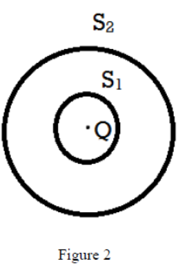
Answer: According to Gauss's theorem, the total electric flux linked with any closed surface is \( \Phi = \frac{q_{\text{enclosed}}}{\varepsilon_0} \).
For the sphere \( S_1 \), the enclosed charge is \( Q \). Thus, \( \Phi_1 = \frac{Q}{\varepsilon_0} \).
For the concentric sphere \( S_2 \), since there are no additional charges between \( S_1 \) and \( S_2 \), the total enclosed charge is still \( Q \). Thus, \( \Phi_2 = \frac{Q}{\varepsilon_0} \).
The ratio of the electric flux through \( S_1 \) and \( S_2 \) is:
\( \frac{\Phi_1}{\Phi_2} = \frac{Q/\varepsilon_0}{Q/\varepsilon_0} = 1 : 1 \).
Question. The V-I graphs of two resistors, and their series combination, are shown in Figure 3. Which one of these graphs represents the series combination of the other two? Give reasons for your answer.
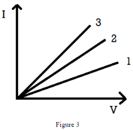
Answer: Graph 1 represents the series combination of the other two resistors.
Reason: The slope of the \( V-I \) graph is \( \frac{I}{V} = \frac{1}{R} \). This means the resistance of a resistor is inversely proportional to the slope of its \( V-I \) curve. In a series combination, the equivalent resistance \( R_s = R_1 + R_2 \) is greater than either of the individual resistances. Since the resistance of the series combination is the highest, its slope on the \( V-I \) graph must be the smallest. Looking at Figure 3, curve 1 has the minimum slope, representing the highest resistance, which corresponds to the series combination.
Question. The following circuit shows the use of potentiometer to measure the internal resistance of a cell:
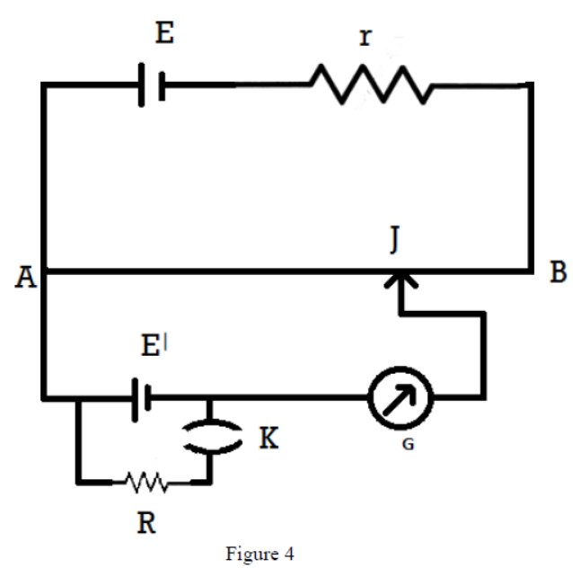
(i). When the key K is open, how does the balance point change, if the current from the driver cell decreases?
(ii). When the key K is closed, how does the balance point change if R is increased, keeping the current from the driver cell constant?
Answer:
(i) When the current from the driver cell decreases, the potential gradient \( k \) along the potentiometer wire decreases. Since \( E = k l \), the balancing length \( l = \frac{E}{k} \) must increase to measure the same emf \( E \). Thus, the balance point shifts towards the right (increases).
(ii) When the key K is closed, the potentiometer measures the terminal potential difference \( V \) of the cell, given by \( V = \frac{E R}{R + r} \). As the shunt resistance \( R \) is increased, the term \( \frac{R}{R + r} = \frac{1}{1 + r/R} \) increases, which increases the terminal potential difference \( V \). Since \( V = k l \), the balancing length \( l = \frac{V}{k} \) must also increase. Thus, the balance point shifts towards the right (increases).
Question. Establish a relation between drift velocity of an electron in a conductor of cross section ‘A’, carrying current ‘I’ and concentration ‘n’ of free electrons per unit volume of conductor.
Answer: Let us consider a conductor of length \( L \) and uniform cross-sectional area \( A \). If \( n \) is the number of free electrons per unit volume, then the total number of free electrons in the conductor is \( N = n A L \).
The total charge of these free electrons is given by:
\( q = N e = n A L e \)
Under the influence of an applied electric field, the free electrons drift with a velocity \( v_d \). The time taken by the free electrons to cross the length \( L \) of the conductor is:
\( t = \frac{L}{v_d} \)
By definition, electric current \( I \) is:
\( I = \frac{q}{t} = \frac{n A L e}{\frac{L}{v_d}} \)
\( I = n e A v_d \)
This is the required relationship between electric current and drift velocity.
Question. Distinguish between diamagnetic and ferromagnetic substances in respect of
(i). Behaviour in a non-uniform magnetic field and
(ii). Susceptibility
Answer:
(i) Behaviour in a non-uniform magnetic field:
- Diamagnetic substances: They are weakly repelled by magnetic fields and tend to move slowly from stronger parts of a non-uniform magnetic field to weaker parts.
- Ferromagnetic substances: They are strongly attracted by magnetic fields and tend to move rapidly from weaker parts of a non-uniform magnetic field to stronger parts.
(ii) Susceptibility (\( \chi_m \)):
- Diamagnetic substances: They have a small, negative magnetic susceptibility (\( -1 \le \chi_m < 0 \)), which is independent of temperature.
- Ferromagnetic substances: They have a very large, positive magnetic susceptibility (\( \chi_m \gg 1 \)), which decreases with an increase in temperature according to the Curie-Weiss Law.
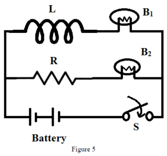
Question. The following figure shows an inductor L and a resistor R connected in parallel to a battery through a switch. The resistance of R is the same as that of the coil that makes L. Two identical bulbs are put in each arm of the circuit.
(i). Which of the bulbs lights up bright when S is closed?
(ii). Will the two bulbs be equally bright after some time?
Give reasons for your answer.
Answer:
(i) When the switch S is closed, bulb \( B_2 \) (connected in series with resistor R) lights up bright instantly. This is because the self-induction of the inductor L opposes the sudden growth of current in its branch by generating a back emf. Consequently, the current in the branch containing bulb \( B_1 \) takes some time to grow to its steady value, causing a delay in its lighting up.
(ii) Yes, after some time, both bulbs \( B_1 \) and \( B_2 \) will be equally bright. Once the current reaches a steady state (DC state), the self-inductive effect of the inductor L vanishes and it behaves as a simple resistor of resistance equal to R. Since both parallel branches have equal total resistance, they will draw equal currents, causing both bulbs to glow with equal brightness.
Question. Identify the part of the electromagnetic spectrum which is
(a). Suitable for radar system used in aircraft navigation
(b). Adjacent to the low frequency end of the electromagnetic spectrum.
(c). Produced in nuclear radiation
(d). Produced by bombarding a metal target by high speed electrons.
Answer:
(a) Microwaves (due to their short wavelengths, they can be directed as narrow beams).
(b) Infrared Rays / Microwaves (adjacent to the low-frequency radio end of the visible spectrum / radio spectrum).
(c) Gamma Rays (emitted during radioactive decay of unstable nuclei).
(d) X-Rays (produced by the sudden deceleration of high-speed electrons striking a heavy metal target).
Question. What changes in the focal length of a
(1). Concave Mirror
(2). Convex Lens
occur when the incident violet light on them is replaced with red light?
Answer:
(1) Concave Mirror: There is no change in its focal length. The focal length of a spherical mirror depends solely on its geometry (\( f = \frac{R}{2} \)) and is independent of the wavelength of incident light.
(2) Convex Lens: Its focal length increases. According to Lens Maker's Formula, \( \frac{1}{f} = (\mu - 1)\left(\frac{1}{R_1} - \frac{1}{R_2}\right) \). Since the refractive index of a material is smaller for red light than for violet light (\( \mu_r < \mu_v \)), replacing violet light with red light decreases the value of \( (\mu - 1) \). Consequently, the focal length \( f \) of the convex lens increases.
Question. Show that the de Broglie wavelength ‘λ’ of electrons accelerated through a potential difference of V volts can be expressed as \( \lambda = \frac{12.3}{\sqrt{V}} \text{ \AA} \)
Answer: The de Broglie wavelength \( \lambda \) of a particle is given by:
\( \lambda = \frac{h}{p} \)
The kinetic energy \( K \) of an electron accelerated through a potential difference of \( V \) volts is \( K = e V \). The relationship between momentum \( p \) and kinetic energy \( K \) is \( p = \sqrt{2mK} \). Therefore:
\( \lambda = \frac{h}{\sqrt{2 m e V}} \)
Substituting the constant values:
Planck's constant, \( h = 6.63 \times 10^{-34} \text{ J}\cdot\text{s} \)
Mass of an electron, \( m = 9.1 \times 10^{-31} \text{ kg} \)
Charge of an electron, \( e = 1.6 \times 10^{-19} \text{ C} \)
\( \lambda = \frac{6.63 \times 10^{-34}}{\sqrt{2 \times 9.1 \times 10^{-31} \times 1.6 \times 10^{-19} \times V}} \)
\( \lambda = \frac{1.227 \times 10^{-9}}{\sqrt{V}} \text{ m} \)
\( \lambda = \frac{12.27}{\sqrt{V}} \text{ \AA} \approx \frac{12.3}{\sqrt{V}} \text{ \AA} \)
Hence proved.
Question. Prove that the radius of the \( n^{\text{th}} \) Bohr orbit of an atom is directly proportional to \( n^2 \), where n is principal quantum number.
Answer: According to Bohr's postulates for a hydrogen-like atom of atomic number \( Z \):
1. The electrostatic force of attraction between the nucleus and the electron provides the necessary centripetal force:
\( \frac{m v^2}{r} = \frac{1}{4\pi\varepsilon_0}\frac{Z e^2}{r^2} \implies m v^2 r = \frac{Z e^2}{4\pi\varepsilon_0} \) --- (1)
2. The angular momentum of the electron is quantized:
\( m v r = \frac{n h}{2\pi} \implies v = \frac{n h}{2\pi m r} \) --- (2)
Substituting the value of \( v \) from (2) into (1):
\( m \left(\frac{n h}{2\pi m r}\right)^2 r = \frac{Z e^2}{4\pi\varepsilon_0} \)
\( \frac{m n^2 h^2}{4\pi^2 m^2 r} = \frac{Z e^2}{4\pi\varepsilon_0} \)
\( r = \frac{n^2 h^2 \varepsilon_0}{\pi m Z e^2} \)
Since \( h, \varepsilon_0, \pi, m, Z, \) and \( e \) are constants for a given atom:
\( r \propto n^2 \)
Hence proved.
Question. How does the size of a nucleus depend on its mass number? Hence explain why the density of nuclear matter should be independent of size of the nucleus.
Answer: The volume of a nucleus is directly proportional to its mass number \( A \). If \( R \) is the radius of the nucleus, then:
\( \frac{4}{3}\pi R^3 \propto A \implies R = R_0 A^{1/3} \)
where \( R_0 \approx 1.2 \times 10^{-15} \text{ m} \) is a constant.
To find the density \( \rho \) of nuclear matter:
\( \rho = \frac{\text{Mass of nucleus}}{\text{Volume of nucleus}} = \frac{A \cdot m}{\frac{4}{3}\pi R^3} \)
where \( m \) is the average mass of a nucleon. Substituting the value of \( R \):
\( \rho = \frac{A \cdot m}{\frac{4}{3}\pi (R_0 A^{1/3})^3} = \frac{A \cdot m}{\frac{4}{3}\pi R_0^3 A} = \frac{3m}{4\pi R_0^3} \)
Since the mass number \( A \) cancels out, the density \( \rho \) depends only on constant quantities (\( m \) and \( R_0 \)). This proves that the density of nuclear matter is constant and independent of the mass number \( A \), and hence independent of the size of the nucleus.
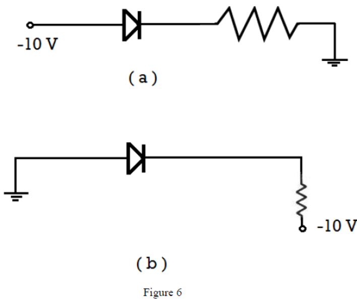
Question. How the thickness of depletion layer in a p-n junction diode changes when it is
(i). Forward biased
(ii). Reversed biased.
In the following circuit which one of the two diodes is forward biased and which is reversed biased?
Answer:
(i) Forward biased: The thickness of the depletion layer decreases because the applied potential opposes the barrier potential, allowing majority carriers to cross the junction.
(ii) Reversed biased: The thickness of the depletion layer increases because the applied potential supports the barrier potential, pulling majority carriers away from the junction.
Circuit Analysis (Figure 6):
- Diode (a): The p-side is connected to a potential of \( -10 \text{ V} \) and the n-side is connected to ground (\( 0 \text{ V} \)). Since the p-side is at a lower potential than the n-side, diode (a) is reversed biased.
- Diode (b): The p-side is connected to ground (\( 0 \text{ V} \)) and the n-side is connected to a potential of \( -10 \text{ V} \). Since the p-side is at a higher potential than the n-side, diode (b) is forward biased.
Question. Define the term modulation. Explain the need of modulating a low frequency information signal.
Answer: Modulation is the process of superimposing a low-frequency message (audio) signal onto a high-frequency carrier wave so that the signal can be transmitted over long distances without attenuation.
Need for modulation:
1. Size of the antenna: For effective transmission, the minimum size of the antenna must be of the order of \( \lambda/4 \). For low-frequency signals (e.g., \( 20 \text{ kHz} \)), the wavelength \( \lambda \) is around \( 15 \text{ km} \), requiring an antenna of height \( 3.75 \text{ km} \), which is practically impossible to construct. High-frequency signals require antennas of realistic sizes.
2. Effective power radiated by antenna: The power radiated by an antenna of length \( l \) is proportional to \( (l/\lambda)^2 \). For a low frequency (large \( \lambda \)), the radiated power is extremely small. High-frequency signals ensure robust power transmission.
3. Avoid mixing of signals: If all transmitters send audio signals directly, they would overlap and interfere, making it impossible to distinguish between them. Carrier modulation separates different channels in the frequency domain.
Question. Define the term LOS. Write the limitation of LOS. Write two techniques used for increasing the range of signal coverage in the LOS.
Answer: LOS (Line of Sight) Propagation: It is a type of space wave propagation in which high-frequency electromagnetic waves (above \( 30 \text{ MHz} \)) travel in a direct straight line from the transmitting antenna to the receiving antenna.
Limitation of LOS: The range of propagation is limited by the curvature of the Earth, which acts as a physical barrier preventing direct reception beyond the horizon.
Two techniques to increase the range:
1. Increasing antenna heights: Increasing the heights of both the transmitting antenna (\( h_T \)) and the receiving antenna (\( h_R \)) expands the line-of-sight distance, given by \( d = \sqrt{2Rh_T} + \sqrt{2Rh_R} \).
2. Using repeaters: Installing intermediate active repeaters (which receive, amplify, and retransmit the signals) between the source and destination extends coverage over vast distances.
Section C ( 3 Marks )
Question. Define electric dipole moment. Derive an expression for the electric field intensity at any point along the equatorial line of an electric dipole.
Answer: Electric Dipole Moment (\( \vec{p} \)): It is defined as the product of the magnitude of either of the charges (\( q \)) and the separation distance between them (\( 2a \)). Its direction is from the negative charge to the positive charge. Mathematically, \( \vec{p} = q(2a)\hat{p} \).
Derivation for Equatorial Line:
Let us consider an electric dipole consisting of two charges \( -q \) and \( +q \) separated by a distance \( 2a \) along the X-axis. Let \( P \) be a point on the equatorial line at a distance \( r \) from its center \( O \).
The distance of point \( P \) from both charges is \( x = \sqrt{r^2 + a^2} \).
The magnitude of the electric field at \( P \) due to the positive charge \( +q \) is:
\( E_+ = \frac{1}{4\pi\varepsilon_0}\frac{q}{r^2 + a^2} \)
The magnitude of the electric field at \( P \) due to the negative charge \( -q \) is:
\( E_- = \frac{1}{4\pi\varepsilon_0}\frac{q}{r^2 + a^2} \)
Since \( E_+ = E_- \), on resolving these fields into components parallel and perpendicular to the dipole axis:
- The components perpendicular to the dipole axis (\( E_+\sin\theta \) and \( E_-\sin\theta \)) are equal in magnitude and opposite in direction, so they cancel out.
- The components parallel to the dipole axis (\( E_+\cos\theta \) and \( E_-\cos\theta \)) act in the same direction (opposite to the dipole moment \( \vec{p} \)) and add up.
The net electric field \( E \) at point \( P \) is:
\( E = E_+\cos\theta + E_-\cos\theta = 2E_+\cos\theta \)
\( E = 2 \left( \frac{1}{4\pi\varepsilon_0}\frac{q}{r^2 + a^2} \right) \cos\theta \)
From the geometry of the triangle, \( \cos\theta = \frac{a}{\sqrt{r^2 + a^2}} \). Substituting this:
\( E = \frac{2q a}{4\pi\varepsilon_0 (r^2 + a^2)^{3/2}} = \frac{p}{4\pi\varepsilon_0 (r^2 + a^2)^{3/2}} \)
For a short dipole (\( r \gg a \)), we neglect \( a^2 \) in comparison to \( r^2 \):
\( E = \frac{p}{4\pi\varepsilon_0 r^3} \)
Vectorially, \( \vec{E} = -\frac{\vec{p}}{4\pi\varepsilon_0 r^3} \).
Question. State Gauss’s theorem in electro statics. Apply this theorem to calculate the electric field due to a uniformly charged spherical shell at a point
(i). Outside the shell
(ii). On the shell
(iii). And inside the shell
Answer: Gauss's Theorem: It states that the net outward electric flux through any closed Gaussian surface in vacuum is equal to \( \frac{1}{\varepsilon_0} \) times the net charge enclosed within that surface. Mathematically, \( \oint \vec{E}\cdot d\vec{A} = \frac{q_{\text{enclosed}}}{\varepsilon_0} \).
Electric Field due to a Spherical Shell (Radius \( R \), total charge \( q \)):
Let us construct a concentric spherical Gaussian surface of radius \( r \). By symmetry, the electric field \( \vec{E} \) is radial and its magnitude is constant at all points on this surface.
\( \oint \vec{E}\cdot d\vec{A} = E \oint dA = E (4\pi r^2) \)
(i) Outside the shell (\( r > R \)):
The Gaussian surface encloses the entire charge \( q \) of the shell.
Applying Gauss's Law:
\( E(4\pi r^2) = \frac{q}{\varepsilon_0} \implies E = \frac{1}{4\pi\varepsilon_0}\frac{q}{r^2} \)
(ii) On the shell (\( r = R \)):
Substituting \( r = R \) in the expression for the external field:
\( E = \frac{1}{4\pi\varepsilon_0}\frac{q}{R^2} \)
(iii) Inside the shell (\( r < R \)):
The Gaussian surface lies entirely inside the shell. Since the charge resides entirely on the outer surface of the shell, the enclosed charge \( q_{\text{enclosed}} = 0 \).
Applying Gauss's Law:
\( E(4\pi r^2) = 0 \implies E = 0 \).
Thus, the electric field inside a charged spherical shell is zero.
Question. A parallel plate capacitor, each with plate area A and separation d, is charge to a potential difference V. The battery used to charge it then disconnected. A dielectric slab of thickness ‘t’ and dielectric constant ‘K’ is now placed between the plates. What change, if any, will take place in:
(i). Charge on the plate
(ii). Electric field intensity between the plates
(iii). Capacitance of the capacitor
Justify your answer in each case.
Answer:
(i) Charge on the plates:
- Change: Remains unchanged (\( Q = Q_0 \)).
- Justification: Since the charging battery has been disconnected, there is no conductive path or source to supply more charge or allow the existing charge to leak off. Therefore, conservation of charge dictates that the charge remains constant.
(ii) Electric field intensity between the plates:
- Change: Decreases.
- Justification: When a dielectric slab is introduced, polarization occurs within the dielectric, creating an induced electric field that opposes the original field. The electric field inside the dielectric reduces to \( \frac{E_0}{K} \). Since the slab has thickness \( t < d \), the net electric field is reduced, lowering the average potential difference \( V \) and the effective field between the plates.
(iii) Capacitance of the capacitor:
- Change: Increases.
- Justification: The new potential difference is \( V' = E_0(d-t) + \frac{E_0}{K}t = V_0 \left[ 1 - \frac{t}{d}\left(1 - \frac{1}{K}\right) \right] \). Since the potential difference decreases while the charge remains constant, the capacitance \( C = \frac{Q}{V'} \) must increase. The new capacitance is \( C = \frac{C_0}{1 - \frac{t}{d}(1 - \frac{1}{K})} \).
Question. State the principle of a potentiometer with the help of a circuit diagram, describe a method to find the internal resistance of a primary cell.
Answer: Principle of a Potentiometer: When a constant current flows through a wire of uniform cross-sectional area and homogeneous composition, the potential drop across any portion of the wire is directly proportional to the length of that portion. Mathematically, \( V \propto l \implies V = k l \), where \( k \) is the potential gradient.
Method to find Internal Resistance:
1. Circuit Connections: Connect the primary cell of emf \( E \) and internal resistance \( r \) in the secondary circuit across the potentiometer wire AB. Connect a resistance box \( R \) and a key \( K_2 \) in parallel with the cell. Connect a galvanometer \( G \) with a jockey \( J \).
2. Step 1 (Open Circuit): Keep key \( K_2 \) open so that no current is drawn from the cell. Slide the jockey along the wire to find the null point at balancing length \( l_1 \). The emf is balanced by the potential drop:
\( E = k l_1 \) --- (1)
3. Step 2 (Closed Circuit): Introduce a known resistance \( R \) from the resistance box and close key \( K_2 \). Slide the jockey to find the new null point at balancing length \( l_2 \). The terminal potential difference \( V \) is balanced by the potential drop:
\( V = k l_2 \) --- (2)
4. Dividing (1) by (2):
\( \frac{E}{V} = \frac{l_1}{l_2} \)
We know the internal resistance formula: \( r = R\left(\frac{E}{V} - 1\right) \).
Substituting \( \frac{E}{V} \):
\( r = R\left(\frac{l_1}{l_2} - 1\right) \)
Using this formula, the internal resistance \( r \) can be determined.
Question. Three identical resistors, each of resistance R, when connected in series with a D.C. source, dissipate power ‘X’. If the resistors are connected in parallel to the same D.C source, how much power will be dissipated?
Answer: Let \( V \) be the voltage of the D.C. source.
Case 1: Series Connection
The equivalent resistance in series is \( R_s = R + R + R = 3R \).
The power dissipated in series is given by:
\( X = \frac{V^2}{R_s} = \frac{V^2}{3R} \implies \frac{V^2}{R} = 3X \) --- (1)
Case 2: Parallel Connection
The equivalent resistance in parallel is \( R_p = \frac{R}{3} \).
The power dissipated in parallel \( P_p \) is:
\( P_p = \frac{V^2}{R_p} = \frac{V^2}{R/3} = \frac{3V^2}{R} \) --- (2)
Substituting equation (1) into (2):
\( P_p = 3 \times (3X) = 9X \)
Thus, the power dissipated in the parallel connection will be \( 9X \).
Question. Derive an expression for the force per unit length experienced by each of the two long current carrying conductors placed parallel to each other in air. Hence define one ampere of Current.
Answer: Let us consider two long, straight parallel conductors carrying currents \( I_1 \) and \( I_2 \) in the same direction, separated by a distance \( r \) in air.
The magnetic field produced by the first conductor carrying current \( I_1 \) at any point on the second conductor is:
\( B_1 = \frac{\mu_0 I_1}{2\pi r} \)
By the right-hand grip rule, this magnetic field is perpendicular to the plane containing both wires.
Since the second conductor carrying current \( I_2 \) lies in this perpendicular magnetic field \( B_1 \), the magnetic force experienced by a segment of length \( L \) of the second conductor is:
\( F_2 = I_2 L B_1 \sin 90^\circ = I_2 L \left( \frac{\mu_0 I_1}{2\pi r} \right) \)
The force per unit length \( f \) is:
\( f = \frac{F_2}{L} = \frac{\mu_0 I_1 I_2}{2\pi r} \)
According to Fleming's Left-Hand Rule, this force is attractive if the currents flow in the same direction.
Definition of One Ampere:
One ampere is that steady current which, when flowing through each of two infinitely long, straight, parallel conductors of negligible cross-section placed 1 meter apart in vacuum, produces between these conductors a force of exactly \( 2 \times 10^{-7} \text{ N/m} \) of their length.
Question. Using Biot-Savart law, derive the expression for the magnetic field due to a current carrying circular loop of radius ‘a’ at a point which is at a distance ‘r’ from its centre along the axis of the loop.
Answer: Let us consider a circular loop of radius \( a \) carrying a current \( I \). Let \( P \) be a point on its axial line at a distance \( r \) from its center \( O \).
Consider a small current element \( dl \) at the top of the loop. The distance from the element to the point \( P \) is \( x = \sqrt{a^2 + r^2} \).
By Biot-Savart Law, the magnetic field \( d\vec{B} \) at \( P \) due to this element \( dl \) is:
\( dB = \frac{\mu_0}{4\pi}\frac{I dl \sin 90^\circ}{x^2} = \frac{\mu_0}{4\pi}\frac{I dl}{a^2 + r^2} \)
The direction of \( d\vec{B} \) is perpendicular to the line joining \( dl \) to \( P \). Resolving \( d\vec{B} \) into two components:
- Components perpendicular to the axis (\( dB\cos\theta \)) cancel out due to diametrically opposite current elements.
- Components along the axial line (\( dB\sin\theta \)) point in the same direction and add up.
The total magnetic field \( B \) at \( P \) is:
\( B = \oint dB\sin\theta = \oint \left( \frac{\mu_0}{4\pi}\frac{I dl}{a^2 + r^2} \right) \sin\theta \)
From the geometry of the figure, \( \sin\theta = \frac{a}{x} = \frac{a}{\sqrt{a^2 + r^2}} \). Substituting this:
\( B = \frac{\mu_0 I a}{4\pi (a^2 + r^2)^{3/2}} \oint dl \)
Since the total length of the loop \( \oint dl = 2\pi a \):
\( B = \frac{\mu_0 I a}{4\pi (a^2 + r^2)^{3/2}} (2\pi a) \)
\( B = \frac{\mu_0 I a^2}{2(a^2 + r^2)^{3/2}} \)
This is the expression for the magnetic field along the axis of the loop.
Question. Define mutual inductance and give its SI unit. Derive an expression for the mutual inductance of two long coaxial solenoids of same length wound over the other.
Answer: Mutual Inductance: It is defined as the magnetic flux linked with the secondary coil when a unit current flows through the primary coil. Alternatively, it is the induced emf produced in the secondary coil due to a unit rate of change of current in the primary coil. Mathematically, \( \Phi_s = M I_p \).
SI Unit: Henry (\( \text{H} \)).
Derivation for Coaxial Solenoids:
Let us consider two long coaxial solenoids \( S_1 \) and \( S_2 \), each of same length \( l \). Let \( S_1 \) be the inner solenoid of radius \( r_1 \) and number of turns \( N_1 \), and \( S_2 \) be the outer solenoid of radius \( r_2 \) and number of turns \( N_2 \).
Let a current \( I_1 \) flow through the inner solenoid \( S_1 \). The magnetic field produced inside \( S_1 \) is:
\( B_1 = \mu_0 n_1 I_1 = \mu_0 \frac{N_1}{l} I_1 \)
The magnetic flux linked with each turn of the outer solenoid \( S_2 \) is \( B_1 A_1 \), where \( A_1 = \pi r_1^2 \).
The total magnetic flux linked with all \( N_2 \) turns of \( S_2 \) is:
\( \Phi_2 = B_1 A_1 N_2 = \left( \mu_0 \frac{N_1}{l} I_1 \right) (\pi r_1^2) N_2 \)
\( \Phi_2 = \left( \frac{\mu_0 N_1 N_2 \pi r_1^2}{l} \right) I_1 \)
We know that \( \Phi_2 = M_{21} I_1 \). Comparing both equations:
\( M_{21} = M = \frac{\mu_0 N_1 N_2 \pi r_1^2}{l} \)
This is the expression for the mutual inductance of the solenoids.
Question. Define displacement current. Write an expression for displacement current. Show that the displacement current across an area in the region between the plates and parallel to it is equal to the conduction current in the connecting wires.
Answer: Displacement Current (\( I_d \)): It is that current which comes into existence in a region where the electric field and hence the electric flux is changing with time.
Expression: \( I_d = \varepsilon_0 \frac{d\Phi_E}{dt} \), where \( \Phi_E \) is the changing electric flux.
Proof of Equality (\( I_d = I_c \)):
Let a parallel plate capacitor of plate area \( A \) be charging with a conduction current \( I_c \) in the connecting wires.
At any instant, if \( Q \) is the charge on the plates, then the electric field \( E \) between the plates is:
\( E = \frac{\sigma}{\varepsilon_0} = \frac{Q}{\varepsilon_0 A} \)
The electric flux \( \Phi_E \) through an area \( A \) between the plates is:
\( \Phi_E = E \cdot A = \left( \frac{Q}{\varepsilon_0 A} \right) A = \frac{Q}{\varepsilon_0} \)
The displacement current \( I_d \) is given by:
\( I_d = \varepsilon_0 \frac{d\Phi_E}{dt} = \varepsilon_0 \frac{d}{dt}\left(\frac{Q}{\varepsilon_0}\right) = \varepsilon_0 \cdot \frac{1}{\varepsilon_0} \frac{dQ}{dt} \)
\( I_d = \frac{dQ}{dt} \)
Since the rate of change of charge \( \frac{dQ}{dt} \) is the conduction current \( I_c \) in the wires, we get:
\( I_d = I_c \).
Thus, the displacement current between the plates is equal to the conduction current in the wires.
Question. Draw a labelled ray diagram to show the formation of an image by a compound microscope. Write the expression for its magnifying power.
Answer: Ray Diagram description: A compound microscope consists of an objective lens of short focal length \( f_o \) and a small aperture, and an eyepiece of moderate focal length \( f_e \) and larger aperture. A small object \( AB \) is placed just beyond the focus of the objective. It forms a real, inverted, and magnified image \( A'B' \). This image acts as virtual object for the eyepiece, which is adjusted so that \( A'B' \) lies within its focal length. The eyepiece forms a highly magnified, virtual, and inverted final image \( A''B'' \) at the least distance of distinct vision \( D \).
Expression for Magnifying Power (\( m \)):
When the final image is formed at the near point \( D \):
\( m = m_o \times m_e \approx -\frac{v_o}{u_o}\left(1 + \frac{D}{f_e}\right) \)
where \( v_o \) and \( u_o \) are the image and object distances for the objective lens, and \( f_e \) is the focal length of the eyepiece.
Question. Describe Davisson and Germer experiment to establish the wave nature of electron. Describe a labelled diagram of the apparatus used.
Answer: Davisson and Germer Experiment: This experiment directly verified de Broglie's hypothesis of the wave nature of moving electrons by demonstrating their wave diffraction.
Apparatus & Working:
- Electron Gun: Consists of a heated tungsten filament coated with barium oxide. Electrons are emitted by thermionic emission and accelerated through a potential difference \( V \).
- Nickel Crystal: The collimated, fine beam of electrons is made to strike the surface of a target Nickel crystal.
- Detector: A movable Faraday cylinder connected to a sensitive galvanometer is used to measure the intensity of the scattered electron beam at different scattering angles \( \theta \).
- Observation: A distinct peak in the intensity of the scattered electrons is observed at a scattering angle \( \phi = 50^\circ \) at an accelerating voltage of \( V = 54\text{ V} \). This peak is due to the constructive interference of electron waves diffracted from the crystal planes. The calculated wavelength matches the de Broglie wavelength \( \lambda = 1.67\text{ \AA} \), establishing the wave nature of electrons.
Question. Draw a diagram to show the variation of binding energy per nucleon with mass number for different nuclei. State with reason why light nuclei usually undergo nuclear fusion.
Answer: Binding Energy per Nucleon Curve: The plot shows a rapid increase for lighter nuclei, peaking around \( \text{Fe}^{56} \) (\( \approx 8.8\text{ MeV} \)), and then gradually decreasing for heavier elements.
Reason why light nuclei undergo nuclear fusion:
Very light nuclei (with mass numbers \( A < 20 \)) have a relatively small binding energy per nucleon, indicating low stability. To achieve greater stability, these light nuclei combine (fuse) to form a heavier, more stable nucleus with a higher binding energy per nucleon. The mass defect in this process is converted into a massive amount of energy according to \( E = \Delta m \cdot c^2 \), which drives the fusion process.
Question. Explain how Rutherford’s experiment on scattering of \( \alpha \)-particles led to the estimation of the size of the nucleus and also define distance of closest approach.
Answer: Estimation of Nuclear Size: In Rutherford's \( \alpha \)-particle scattering experiment, most of the \( \alpha \)-particles passed undeflected, but a very small fraction (1 in 8000) was deflected back by \( 180^\circ \). This indicated that the entire positive charge and almost the entire mass of the atom are concentrated in an extremely small region at the center, called the nucleus. By calculating the distance up to which an \( \alpha \)-particle can approach before stopping, Rutherford estimated the size of the nucleus to be around \( 10^{-14}\text{ m} \) to \( 10^{-15}\text{ m} \).
Distance of Closest Approach (\( r_0 \)):
It is the minimum distance up to which a fast-moving \( \alpha \)-particle can approach the center of a nucleus along a head-on path before its entire kinetic energy is temporarily converted into electrostatic potential energy.
At \( r_0 \):
\( K.E. = U_E \implies \frac{1}{2} m v^2 = \frac{1}{4\pi\varepsilon_0}\frac{(2e)(Ze)}{r_0} \)
\( r_0 = \frac{1}{4\pi\varepsilon_0}\frac{4 Z e^2}{m v^2} \)
Question. With the help of a labelled circuit diagram, explain the use of junction diodes as a full wave rectifier. Draw the input and output waveforms.
Answer: Working of a Full Wave Rectifier:
A full wave rectifier uses two junction diodes \( D_1 \) and \( D_2 \) connected to the secondary terminals of a center-tapped transformer. The load resistor \( R_L \) is connected between the center-tap and the junction of the cathodes of the two diodes.
1. Positive Half-Cycle: Terminal \( A \) of the transformer becomes positive and \( B \) becomes negative. Diode \( D_1 \) is forward-biased and conducts, while \( D_2 \) is reverse-biased and does not conduct. Current flows through \( R_L \) from top to bottom.
2. Negative Half-Cycle: Terminal \( A \) becomes negative and \( B \) becomes positive. Diode \( D_2 \) becomes forward-biased and conducts, while \( D_1 \) is reverse-biased. Current again flows through \( R_L \) in the same direction (top to bottom).
Thus, output is obtained for both halves of the AC input cycle, producing a continuous unidirectional pulsating DC voltage across \( R_L \).
Question. Describe the different types in which electromagnetic waves can propagate from one point to another.
Answer: Electromagnetic waves propagate through space via three main modes depending on their frequency:
1. Ground Wave (Surface Wave) Propagation: The waves travel along the surface of the Earth. It is useful for low-frequency waves (typically below \( 2 \text{ MHz} \)) because higher frequencies suffer severe attenuation due to absorption by the ground.
2. Sky Wave Propagation: High-frequency waves (from \( 2 \text{ MHz} \) to \( 30 \text{ MHz} \)) are transmitted towards the sky and reflected back to Earth by the ionospheric layers. This mode is used for long-distance shortwave radio communication.
3. Space Wave Propagation: Very high-frequency waves (above \( 30 \text{ MHz} \)), such as TV and FM signals, travel directly in a straight line from the transmitter to the receiver (Line of Sight) or are relayed via satellites in space.
Section D ( 5 Marks )
Question. Draw a neat and labelled diagram of cyclotron. State the underlying principle and explain how a positively charged particles gets accelerated in this machine. Show mathematically that the cyclotron frequency does not depend upon the speed of the particle.
Answer: Underlying Principle: A charged particle can be accelerated to high energies by passing it repeatedly through a moderate electric field. This is achieved by using a perpendicular magnetic field that forces the particle to travel in circular paths, synchronized with a high-frequency alternating electric field.
Working & Acceleration:
The cyclotron consists of two hollow semicircular metal chambers called ‘Dees’ placed in a strong magnetic field. A high-frequency oscillator is connected across the Dees. A positive ion source is placed at the center. As the ion enters the gap, the electric field accelerates it into one of the Dees, where the magnetic field bends it into a semicircle. When it exits the Dee, the oscillator polarities reverse, accelerating the ion across the gap into the other Dee with greater speed and radius. This process repeats until the ion reaches the periphery and is extracted.
Independence of Frequency from Speed:
The magnetic force provides the necessary centripetal force:
\( q v B = \frac{m v^2}{r} \implies v = \frac{q B r}{m} \)
The time taken to complete one half-revolution inside a Dee is:
\( t = \frac{\pi r}{v} = \frac{\pi r}{\frac{q B r}{m}} = \frac{\pi m}{q B} \)
The total time period of one full revolution is \( T = 2t = \frac{2\pi m}{q B} \).
The cyclotron frequency \( f_c \) is:
\( f_c = \frac{1}{T} = \frac{q B}{2\pi m} \)
Since \( q, B, \) and \( m \) are constants, the frequency of rotation is independent of the speed \( v \) and the radius \( r \) of the particle's path.
Question. With the help of a neat and labelled diagram, explain the underlying principle and working of a moving coil galvanometer. What is the function of
(i). Uniform radial field
(ii). Soft iron core, in such a device?
Answer: Principle: When a current-carrying coil is placed in a uniform magnetic field, it experiences a magnetic torque \( \tau \). The torque causes a deflection that is balanced by the restoring torque of a suspension spring.
Working:
The deflecting torque acting on the coil of \( N \) turns, area \( A \), carrying current \( I \) in a magnetic field \( B \) is:
\( \tau = N I A B \sin\theta \)
The deflection of the coil winds the spring, generating a restoring torque \( \tau_r = k \phi \), where \( k \) is the torsional constant. At equilibrium:
\( N I A B \sin\theta = k \phi \)
Functions:
(i) Uniform radial field: Curved pole pieces are used to create a radial magnetic field. This ensures that the plane of the coil remains parallel to the magnetic field lines (\( \theta = 90^\circ \)) in all positions. Consequently, \( \sin\theta = 1 \), making the torque directly proportional to current: \( \tau = N I A B \implies \phi \propto I \). This results in a linear scale.
(ii) Soft iron core: The cylindrical soft iron core placed inside the coil concentrates the magnetic field lines due to its high permeability, thereby significantly increasing the magnetic field \( B \) and enhancing the sensitivity of the galvanometer.
Question. Using phasor diagram, derive an expression for the impedance of a series LCR-circuit. What do you mean by resonance condition of such a circuit? Find an expression for Q-factor of the circuit.
Answer: Derivation of Impedance:
Let an alternating voltage \( V = V_0\sin\omega t \) be applied across a series combination of \( L, C, \) and \( R \). Let \( I \) be the instantaneous current. The voltage phasors across the components are:
- \( V_R = I R \), in phase with \( I \).
- \( V_L = I X_L \), leading \( I \) by \( 90^\circ \).
- \( V_C = I X_C \), lagging \( I \) by \( 90^\circ \).
Assuming \( V_L > V_C \), the net reactive voltage is \( V_L - V_C \). From the vector phasor diagram, the resultant source voltage \( V_0 \) is:
\( V_0^2 = V_R^2 + (V_L - V_C)^2 \)
\( V_0^2 = (I_0 R)^2 + (I_0 X_L - I_0 X_C)^2 \)
\( V_0 = I_0 \sqrt{R^2 + (X_L - X_C)^2} \)
The impedance \( Z \) is defined as \( Z = \frac{V_0}{I_0} \):
\( Z = \sqrt{R^2 + (X_L - X_C)^2} \)
Resonance Condition:
Resonance occurs when the current amplitude in the circuit becomes maximum. This happens when the inductive reactance equals the capacitive reactance:
\( X_L = X_C \implies \omega_0 L = \frac{1}{\omega_0 C} \implies \omega_0 = \frac{1}{\sqrt{LC}} \)
At resonance, the impedance is minimum (\( Z = R \)).
Q-Factor (Quality Factor):
The Q-factor measures the sharpness of resonance and is defined as:
\( Q = \frac{\omega_0 L}{R} = \frac{1}{R}\sqrt{\frac{L}{C}} \).
Question. With the help of a labelled diagram, explain the principle, construction and working of an A.C. generator. Derive the expression for induced emf.
Answer: Principle: It is based on the principle of electromagnetic induction. When a closed armature coil is rotated in a uniform magnetic field, the magnetic flux linked with it changes continuously, inducing an alternating emf in the coil.
Construction & Working:
It consists of an armature coil \( PQRS \) rotated mechanically between the curved poles of a strong electromagnet. The ends of the coil are connected to slip rings \( R_1, R_2 \) which rotate with the coil. Stationary carbon brushes \( B_1, B_2 \) press against the rings to collect the current.
As the coil rotates, the angle \( \theta = \omega t \) between the area vector \( \vec{A} \) and magnetic field \( \vec{B} \) changes continuously. This changes the linked flux \( \Phi = N B A \cos(\omega t) \), inducing an alternating emf across the brushes.
Derivation of Induced EMF:
By Faraday's Law of Electromagnetic Induction, the induced emf \( \varepsilon \) is:
\( \varepsilon = -N \frac{d\Phi}{dt} = -N \frac{d}{dt}(B A \cos\omega t) \)
\( \varepsilon = -N B A (-\omega \sin\omega t) \)
\( \varepsilon = N B A \omega \sin\omega t \)
Let \( \varepsilon_0 = N B A \omega \) be the peak value of the emf:
\( \varepsilon = \varepsilon_0 \sin\omega t \).
Question. Derive the relation between distance of object, distance of image and radius of curvature of convex spherical surface, when refraction takes place from a rarer medium of refractive index µ1 to a denser medium of refractive index µ2 and the image produced is real. State the assumptions used.
Answer: Assumptions: (1) The object is a point object lying on the principal axis. (2) The aperture of the refracting surface is small. (3) The incident and refracted rays make very small angles with the principal axis (paraxial rays), allowing \( \sin\theta \approx \theta \) and \( \tan\theta \approx \theta \).
Derivation:
Let \( O \) be a point object in the rarer medium (\( \mu_1 \)) and \( I \) be its real image formed in the denser medium (\( \mu_2 \)) after refraction through a convex spherical surface of radius \( R \). Let \( C \) be the center of curvature.
Using Snell's Law:
\( \mu_1 \sin i = \mu_2 \sin r \implies \mu_1 i \approx \mu_2 r \) --- (1)
From the triangles in the ray diagram:
Exterior angle \( i = \alpha + \gamma \)
Exterior angle \( \gamma = r + \beta \implies r = \gamma - \beta \)
Substituting \( i \) and \( r \) in (1):
\( \mu_1 (\alpha + \gamma) = \mu_2 (\gamma - \beta) \) --- (2)
Since the angles are small, we approximate them by their tangents:
\( \alpha \approx \tan\alpha = \frac{AN}{NO} \approx \frac{AN}{-u} \)
\( \beta \approx \tan\beta = \frac{AN}{NI} \approx \frac{AN}{v} \)
\( \gamma \approx \tan\gamma = \frac{AN}{NC} \approx \frac{AN}{R} \)
Substituting these values into (2):
\( \mu_1 \left( \frac{AN}{-u} + \frac{AN}{R} \right) = \mu_2 \left( \frac{AN}{R} - \frac{AN}{v} \right) \)
Canceling \( AN \) from both sides and rearranging:
\( -\frac{\mu_1}{u} + \frac{\mu_1}{R} = \frac{\mu_2}{R} - \frac{\mu_2}{v} \)
\( \frac{\mu_2}{v} - \frac{\mu_1}{u} = \frac{\mu_2 - \mu_1}{R} \)
This is the required refraction formula.
Question. Draw a graph to show the variation of the angle of deviation ‘δ’ with that of angle of incidence ‘i’ for a monochromatic ray of light passing through a glass prism of refracting angle A. hence deduce the expression for the refractive index of the material of the prism in terms of the angle of prism and the angle of minimum deviation.
Answer: Derivation of Prism Formula:
We know the relation for a prism is:
\( A + \delta = i + e \) --- (1)
At the position of minimum deviation (\( \delta = \delta_m \)), the ray passes symmetrically through the prism, so:
\( i = e \quad \text{and} \quad r_1 = r_2 = r \)
Substituting these conditions into (1):
\( A + \delta_m = 2i \implies i = \frac{A + \delta_m}{2} \)
Also, we know that \( r_1 + r_2 = A \). Substituting \( r_1 = r_2 = r \):
\( 2r = A \implies r = \frac{A}{2} \)
Applying Snell's Law for the refractive index \( \mu \) of the prism material:
\( \mu = \frac{\sin i}{\sin r} \)
Substituting the values of \( i \) and \( r \):
\( \mu = \frac{\sin\left(\frac{A + \delta_m}{2}\right)}{\sin\left(\frac{A}{2}\right)} \)
This is the required expression for the refractive index.
Question. What is an astronomical telescope? Describe its construction and working. Derive its magnifying power when the final image is formed at the least distance of distinct vision. Why should the diameter of the objective of a telescope be large?
Answer: Astronomical Telescope: It is an optical instrument used to see distant celestial bodies such as stars, planets, and satellites.
Construction & Working:
It consists of two converging lenses:
- Objective Lens: Facing the object, it has a large focal length \( f_o \) and a large aperture to gather maximum light.
- Eyepiece: Facing the eye, it has a short focal length \( f_e \) and a small aperture.
Parallel rays from a distant object enter the objective and form a real, inverted image \( A'B' \) at its focus \( f_o \). The eyepiece is adjusted so that \( A'B' \) lies within its focal length. The eyepiece then acts as a simple magnifier, producing a highly magnified virtual final image \( A''B'' \).
Magnifying Power (\( m \)):
When the final image is formed at the near point \( D \):
\( m = \frac{\beta}{\alpha} \approx \frac{\tan\beta}{\tan\alpha} \)
Using lens formula, we derive:
\( m = -\frac{f_o}{f_e}\left(1 + \frac{f_e}{D}\right) \)
Reason for Large Objective Diameter:
1. Light Gathering Power: A larger objective collects more light, producing a brighter image of distant, faint stars.
2. Resolving Power: Resolving power is proportional to the diameter \( D \) of the objective (\( R.P. = \frac{D}{1.22 \lambda} \)). A larger aperture allows the telescope to resolve closely spaced celestial objects.
Question. Using Huygens’s principle, explain diffraction of light due to a single slit illuminated by a monochromatic source. Explain the formation of the pattern of the fringes on the screen.
Answer: Diffraction at a Single Slit:
Let a plane wavefront of wavelength \( \lambda \) fall on a slit AB of width \( d \). According to Huygens's principle, every point on the wavefront within the slit acts as a source of secondary wavelets. These wavelets propagate in all directions and interfere to form a diffraction pattern on the screen.
Formation of Fringes:
1. Central Maximum: Wavelets travelling straight (at angle \( \theta = 0 \)) arrive at the center of the screen in phase and reinforce each other constructively, forming a very bright central maximum.
2. Minima Condition: For wavelets diffracted at an angle \( \theta \), the path difference between the wavelets from ends A and B is \( d\sin\theta \). If \( d\sin\theta = n\lambda \) (where \( n = 1, 2, 3 \dots \)), the slit can be divided into \( 2n \) equal parts. The wavelets from corresponding points in adjacent parts interfere destructively, producing a minimum.
3. Secondary Maxima Condition: If \( d\sin\theta = (2n + 1)\frac{\lambda}{2} \), the slit can be divided into \( 2n+1 \) parts. The wavelets from \( 2n \) parts cancel each other out, while those from the remaining \( 1 \) part interfere constructively to produce a weak secondary maximum.
Question. Draw a circuit diagram to study the input and output characteristics of an n-p-n transistor in common emitter configuration. Show these graphically. Explain how (i) input resistance and (ii) output resistance, are calculated using these characteristics.
Answer: Characteristics:
- Input Characteristics: Plot of base current \( I_B \) versus base-emitter voltage \( V_{BE} \) at a constant collector-emitter voltage \( V_{CE} \).
- Output Characteristics: Plot of collector current \( I_C \) versus collector-emitter voltage \( V_{CE} \) at a constant base current \( I_B \).
Calculations:
(i) Input Resistance (\( r_i \)): It is defined as the ratio of change in base-emitter voltage to the corresponding change in base current at a constant collector-emitter voltage:
\( r_i = \left( \frac{\Delta V_{BE}}{\Delta I_B} \right)_{V_{CE} = \text{constant}} \)
It is calculated by taking the reciprocal of the slope of the input characteristics curve.
(ii) Output Resistance (\( r_o \)): It is defined as the ratio of change in collector-emitter voltage to the corresponding change in collector current at a constant base current:
\( r_o = \left( \frac{\Delta V_{CE}}{\Delta I_C} \right)_{I_B = \text{constant}} \)
It is calculated from the reciprocal of the slope of the output characteristics curve in the active region.
Question. Define the terms depletion layer and Potential barrier. With the help of labelled diagram, explain the use of a Zener diode as a voltage regulator.
Answer: Depletion Layer: It is a thin region around the p-n junction that is completely devoid of mobile charge carriers (electrons and holes) due to their diffusion across the junction, leaving behind immobile donor and acceptor ions.
Potential Barrier: The potential difference developed across the depletion layer due to the accumulated immobile ions which prevents further diffusion of majority charge carriers across the junction.
Zener Diode as a Voltage Regulator:
A Zener diode is operated in its reverse breakdown region, where the voltage across it remains constant (\( V_Z \)) even when the current through it changes significantly.
Working:
The unregulated DC input voltage is connected across the Zener diode in reverse bias through a series resistor \( R_s \). The load resistance \( R_L \) is connected in parallel with the Zener diode.
- If the input voltage increases, the current through the circuit increases, causing an increase in the potential drop across \( R_s \). The voltage across the Zener diode, and hence across the load \( R_L \), remains constant at \( V_Z \).
- If the input voltage decreases, the current decreases, lowering the drop across \( R_s \) while maintaining the regulated output voltage \( V_Z \) across \( R_L \).
Free study material for Physics
Free CBSE Practice Worksheets: Class 12 Physics Short Answer Question Bank
Mastering Short Answer Question Bank with Printable Worksheets
Review targeted practice exercises for Class 12 Physics Short Answer Question Bank. Curated to match official CBSE guidelines, these printable problem sets support daily revision and improve overall test readiness.
Verified Solutions and NCERT Alignment
Built using official NCERT guidelines for Class 12 Physics, these practice sheets provide reliable academic support. Cross-reference your completed work with our detailed solutions to learn standard answer-writing formats for CBSE exams.
Additional Study Resources for Class 12 Physics
Consistent engagement with these exercises builds familiarity with recurring exam themes. If specific areas within Short Answer Question Bank cause trouble, utilize our dedicated NCERT solutions for Class 12 Physics to clear up doubts immediately.
FAQs
You can download the latest chapter-wise printable worksheets for Class 12 Physics Short Answer Question Bank for free from StudiesToday.com. These have been made as per the latest CBSE curriculum for this academic year.
Yes, Class 12 Physics worksheets for Short Answer Question Bank focus on activity-based learning and also competency-style questions. This helps students to apply theoretical knowledge to practical scenarios.
Yes, we have provided solved worksheets for Class 12 Physics Short Answer Question Bank to help students verify their answers instantly.
Yes, our Class 12 Physics test sheets are mobile-friendly PDFs and can be printed by teachers for classroom.
For Short Answer Question Bank, regular practice with our worksheets will improve question-handling speed and help students understand all technical terms and diagrams.