

Download Class 12 Physics Practice Worksheets
Review targeted academic worksheets with the CBSE Class 12 Physics Quick Revision Questions Worksheet Set 03. Built according to official educational standards for the 2026-27 term, these downloadable Class 12 Physics resources support effective daily practice and detailed self-evaluation for Quick Questions.
Access Quick Questions Practice Papers and Solutions
View or download the dedicated CBSE Class 12 Physics Quick Revision Questions Worksheet Set 03 resource below. Engaging with these practice papers under focused study conditions ensures continuous academic progress and mastery of the 2026-27 curriculum for Quick Questions.
CBSE Class 12 Physics Quick Revision Questions (3). Students can download these worksheets and practice them. This will help them to get better marks in examinations. Also refer to other worksheets for the same chapter and other subjects too. Use them for better understanding of the subjects.
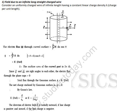
Question 1. Field due to an infinite long straight charged wire
Answer: Consider an infinitely long, uniformly charged straight wire carrying a constant linear charge density \( \lambda \) (charge per unit length). To determine the electric field \( \vec{E} \) at a distance \( r \) from the wire, we construct a cylindrical Gaussian surface of radius \( r \) and length \( l \) coaxial with the wire.
The total electric flux \( \Phi \) passing through this cylindrical Gaussian surface is the sum of the fluxes through the curved surface and the flat end caps:
1. Since the electric field \( \vec{E} \) is parallel to the area vectors of the curved surface, the angle \( \theta = 0^\circ \):
\( \Phi_{\text{curved}} = \int E \cdot ds \cos 0^\circ = E \int ds = E(2\pi r l) \)
2. For the flat circular end caps, the electric field is perpendicular to the area vectors (\( \theta = 90^\circ \)), so the flux through them is zero.
Therefore, the total flux through the Gaussian cylinder is:
\( \Phi = E (2\pi r l) \)
The total charge enclosed within this Gaussian surface is:
\( q = \lambda l \)
According to Gauss's Law:
\( \Phi = \frac{q}{\varepsilon_0} \)
\( \implies E (2\pi r l) = \frac{\lambda l}{\varepsilon_0} \)
\( \implies E = \frac{\lambda}{2\pi \varepsilon_0 r} \).
The electric field is directed radially outward if the charge is positive, and radially inward if the charge is negative.
In simple words: To find the electric field around a long charged wire, we imagine a cylinder surrounding it. Applying Gauss's Law shows that the electric field decreases as you move further away from the wire.
Exam Tip: Always draw the cylindrical Gaussian surface and show that the flux through the flat circular caps is zero because the electric field is perpendicular to their surface vectors.
Question 2. Consider a dipole AB of dipole moment p placed at an angle θ in an uniform electric field E
Answer: Consider an electric dipole consisting of two equal and opposite charges \( -q \) and \( +q \) separated by a distance \( 2d \), placed at an angle \( \theta \) in a uniform electric field \( \vec{E} \).
The charges experience equal and opposite electrostatic forces \( \vec{F} = q\vec{E} \) and \( -\vec{F} = -q\vec{E} \). Since these forces are equal in magnitude and opposite in direction, the net translational force acting on the dipole is zero, keeping it in translational equilibrium.
However, because these forces act along different lines of action, they exert a rotational torque \( \tau \). The magnitude of this torque is:
\( \tau = \text{Force} \times \text{Perpendicular distance between the two forces} \)
\( \implies \tau = (qE) \times (2d \sin\theta) \)
Since the electric dipole moment is \( p = q \times 2d \):
\( \implies \tau = pE \sin\theta \).
The direction of the torque is perpendicular to the plane containing \( \vec{p} \) and \( \vec{E} \). In vector form:
\( \vec{\tau} = \vec{p} \times \vec{E} \).
In simple words: When a dipole is placed at an angle in a uniform electric field, the positive and negative ends are pulled in opposite directions. These equal pulls do not move it sideways, but they twist it to align with the field.
Exam Tip: Be sure to write the torque in its vector form \( \vec{\tau} = \vec{p} \times \vec{E} \) and mention that it is maximum when \( \theta = 90^\circ \).
Question 3. Electric field due to an infinite charged plane sheet
Answer: Consider an infinite plane sheet of charge carrying a uniform surface charge density \( \sigma \). To find the electric field \( \vec{E} \) at a nearby point \( P \) at a distance \( r \) from the sheet, we construct a cylindrical Gaussian surface of cross-sectional area \( A \) perpendicular to the sheet, extending symmetrically to a distance \( r \) on both sides.
By symmetry, the electric field lines are directed perpendicular to the sheet and point outward on both sides. Consequently, the electric flux through the curved side of the cylinder is zero because the field is parallel to this surface.
The total electric flux through both circular flat end caps of area \( A \) is:
\( \Phi = \int_{P} E \cdot ds + \int_{P'} E \cdot ds = E A + E A = 2 E A \)
The total charge enclosed within the Gaussian cylinder is:
\( q = \sigma A \)
Applying Gauss's Law:
\( \Phi = \frac{q}{\varepsilon_0} \)
\( \implies 2 E A = \frac{\sigma A}{\varepsilon_0} \)
\( \implies E = \frac{\sigma}{2 \varepsilon_0} \).
This shows that the electric field due to an infinite plane sheet of charge is independent of the distance \( r \) from the sheet.
In simple words: To find the electric field near a large charged sheet, we imagine a cylinder passing through it. Using Gauss's Law on the flat ends of this cylinder shows that the electric field strength is constant and doesn't change even if you move further away.
Exam Tip: Emphasize that the electric field does not depend on the distance \( r \) from the sheet, which is a unique characteristic of an infinite plane of charge.
Question 4. Electric field due to uniformly charged spherical shell
Answer: Let us consider a thin spherical shell of radius \( R \) carrying a uniform total charge \( q \). We evaluate the electric field \( \vec{E} \) at a distance \( r \) from the center of the shell in three different cases:
Case (i): At an external point (\( r > R \))
We construct a concentric spherical Gaussian surface of radius \( r \). The total electric flux passing normally outward through this surface is:
\( \Phi = \int E \cdot ds = E \int ds = E (4\pi r^2) \) --- (1)
According to Gauss's Law:
\( \Phi = \frac{q}{\varepsilon_0} \) --- (2)
Equating (1) and (2):
\( E(4\pi r^2) = \frac{q}{\varepsilon_0} \implies E = \frac{1}{4\pi \varepsilon_0} \frac{q}{r^2} \).
This demonstrates that for points outside the shell, the entire charge behaves as if it were concentrated at the center.
Case (ii): At a point on the surface (\( r = R \))
Substituting \( r = R \) into the external field formula yields:
\( E = \frac{1}{4\pi \varepsilon_0} \frac{q}{R^2} \).
Case (iii): At an internal point (\( r < R \))
We draw a concentric spherical Gaussian surface of radius \( r \). Since all the charge resides entirely on the outer surface of the shell, the net charge enclosed inside this internal Gaussian surface is zero (\( q_{\text{enclosed}} = 0 \)).
Applying Gauss's Law:
\( E(4\pi r^2) = \frac{q_{\text{enclosed}}}{\varepsilon_0} = 0 \implies E = 0 \).
Thus, the electric field is zero at all points inside a uniformly charged thin spherical shell.
In simple words: Outside a charged metal ball, the electric field looks exactly as if all the charge is packed into a tiny point at the very center. However, inside the hollow space of the ball, the electric field is completely zero because there is no charge enclosed.
Exam Tip: Be prepared to draw the graph showing how the electric field \( E \) is zero when \( r < R \), reaches its maximum at \( r = R \), and then drops off as \( \frac{1}{r^2} \) when \( r > R \).
Question 5. Electric potential energy of an electric dipole in an electric field.
Answer: The electric potential energy of a dipole in an electrostatic field is defined as the work done in rotating it from a standard perpendicular orientation (\( 90^\circ \)) to its present orientation within the electric field.
When a dipole with dipole moment \( p \) is oriented at an angle \( \theta \) with respect to an electric field \( E \), the restorative torque experienced is:
\( \tau = pE \sin\theta \delta \)
The small amount of work done \( dw \) in rotating the dipole through a tiny angle \( d\theta \) is:
\( dw = \tau \cdot d\theta = pE \sin\theta \cdot d\theta \)
To find the total work done in rotating the dipole from an initial angle \( \theta_1 \) to a final angle \( \theta_2 \), we integrate:
\( W = \int_{\theta_1}^{\theta_2} pE \sin\theta \cdot d\theta = -pE [\cos\theta]_{\theta_1}^{\theta_2} = pE(\cos\theta_1 - \cos\theta_2) \)
By taking the reference angle \( \theta_1 = \frac{\pi}{2} \) (where potential energy is defined to be zero) and the final angle \( \theta_2 = \theta \), the potential energy \( U \) stored in the dipole is:
\( U(\theta) = pE \left(\cos\frac{\pi}{2} - \cos\theta\right) = -pE \cos\theta \)
In vector notation:
\( U = -\vec{p} \cdot \vec{E} \).
This shows that the potential energy of the dipole is minimum (\( -pE \)) when it is aligned parallel to the field (\( \theta = 0^\circ \)), representing stable equilibrium.
In simple words: The potential energy of a dipole is the energy stored when we twist it against the electrical forces. It is lowest when the dipole points in the same direction as the electric field, which is its most stable, relaxed state.
Exam Tip: Remember to state the special cases: stable equilibrium at \( \theta = 0^\circ \) where \( U = -pE \), and unstable equilibrium at \( \theta = 180^\circ \) where \( U = +pE \).
Question 6. Capacitance of a parallel plate capacitor with a dielectric medium.
Answer: Consider a parallel-plate capacitor with plate area \( A \) and plate separation \( d \). Let a dielectric slab of thickness \( t \) (\( t < d \)) and relative permittivity \( \varepsilon_r \) (or dielectric constant \( K \)) be placed between the plates.
The total distance between the plates is divided into two regions:
1. An air gap of thickness \( (d - t) \) with electric field \( E = \frac{\sigma}{\varepsilon_0} \).
2. A dielectric slab of thickness \( t \) with a reduced electric field \( E' = \frac{E}{\varepsilon_r} = \frac{\sigma}{\varepsilon_r \varepsilon_0} \).
The total potential difference \( V \) across the plates of the capacitor is the sum of the potentials across these two regions:
\( V = E(d - t) + E' t \)
\( \implies V = \frac{\sigma}{\varepsilon_0}(d - t) + \frac{\sigma}{\varepsilon_r \varepsilon_0} t \)
\( \implies V = \frac{\sigma}{\varepsilon_0} \left[ (d - t) + \frac{t}{\varepsilon_r} \right] \)
Since the charge on the plate is \( q = \sigma A \), the capacitance \( C \) of the system is:
\( C = \frac{q}{V} = \frac{\sigma A}{\frac{\sigma}{\varepsilon_0} \left[ (d - t) + \frac{t}{\varepsilon_r} \right]} \)
\( \implies C = \frac{\varepsilon_0 A}{(d - t) + \frac{t}{\varepsilon_r}} \).
Special Cases:
(i) If the dielectric fills the entire space (\( t = d \)):
\( C' = \frac{\varepsilon_r \varepsilon_0 A}{d} = \varepsilon_r C \)
(ii) If the slab is a conducting plate (\( \varepsilon_r = \infty \)):
\( C = \frac{\varepsilon_0 A}{d - t} \).
In simple words: Adding a solid insulating block inside a capacitor reduces the strength of the electric field inside that block. Because the voltage drops as a result, the capacitor is able to store more charge for the same voltage, increasing its overall capacitance.
Exam Tip: The formula \( C = \frac{\varepsilon_0 A}{(d-t) + t/\varepsilon_r} \) is extremely important. Be sure to show both special cases (\( t=d \) and \( t=0 \)) to demonstrate complete mastery.
Question 7. Energy stored in a capacitor
Answer: A capacitor is a device designed to store electrical charge. This charging process requires performing work against the accumulating electrostatic repulsion on the plates. The work done is fully stored within the capacitor as electrostatic potential energy \( U \).
Let \( q \) be the charge and \( V = \frac{q}{C} \) be the potential difference across the plates of the capacitor at any intermediate stage of charging. The small amount of work \( dw \) required to transfer an additional charge \( dq \) is:
\( dw = V \cdot dq = \frac{q}{C} dq \)
The total work done \( W \) to charge the capacitor from a completely uncharged state to a final charge \( Q \) is calculated by integrating:
\( W = \int_0^Q \frac{q}{C} dq = \frac{1}{C} \left[ \frac{q^2}{2} \right]_0^Q = \frac{Q^2}{2C} \)
Since this work is fully stored as potential energy \( U \):
\( U = \frac{Q^2}{2C} \)
Using the identity \( Q = C V \), we can express this energy in three equivalent mathematical forms:
\( U = \frac{1}{2} \frac{Q^2}{C} = \frac{1}{2} C V^2 = \frac{1}{2} Q V \).
In simple words: To charge a capacitor, you have to push extra charges onto plates that already have charges on them. The total energy you spend doing this is stored as electrical energy, which equals half of the capacitance multiplied by the square of the voltage.
Exam Tip: Clearly list all three equivalent formulas (\( \frac{1}{2}CV^2 \), \( \frac{Q^2}{2C} \), and \( \frac{1}{2}QV \)) because different exam questions will require different forms based on what values are given.
Question 8. Energy stored in a capacitor
Answer: The potential energy stored in a charged capacitor can be expressed in terms of the charge \( q \), capacitance \( C \), and potential difference \( V \) as:
\( U = \frac{1}{2} \frac{q^2}{C} = \frac{1}{2} C V^2 \).
This expression represents the total electrical potential energy held within the electrostatic field between the plates.
In simple words: The total energy stored in a capacitor can be written using its charge, voltage, or capacitance, showing how energy is kept in the electric field.
Exam Tip: Make sure to remember that this stored energy is physically located inside the electric field between the capacitor's plates.
Question 9. Energy Density of a capacitor
Answer: Energy density \( u \) is defined as the electrostatic potential energy stored per unit volume of space between the plates of the capacitor.
The total energy \( U \) stored in a parallel plate capacitor is:
\( U = \frac{1}{2} C V^2 \)
Since the capacitance is \( C = \frac{\varepsilon_0 A}{d} \) and the potential difference is \( V = E \cdot d \), we can substitute these values:
\( U = \frac{1}{2} \left( \frac{\varepsilon_0 A}{d} \right) (E d)^2 = \frac{1}{2} \varepsilon_0 E^2 (A d) \)
Here, the product \( A \cdot d \) represents the volume of the region between the plates where the electric field exists.
Therefore, the energy density \( u \) is:
\( u = \frac{U}{\text{Volume}} = \frac{\frac{1}{2} \varepsilon_0 E^2 (A d)}{A d} \)
\( \implies u = \frac{1}{2} \varepsilon_0 E^2 \).
This shows that the energy density depends solely on the electric field strength \( E \) at that point in space.
In simple words: Energy density is the amount of electrical energy packed into each cubic centimeter of the space between the plates. It depends only on the square of the electric field strength.
Exam Tip: Always highlight that the energy density formula \( u = \frac{1}{2}\varepsilon_0 E^2 \) is a general result that applies to any electric field in a vacuum, not just inside a capacitor.
Question 10. Derive the relation between surface charge density and the radius of a charged sphere
Answer: Consider two isolated conducting spheres, \( A \) and \( B \), of radii \( r_1 \) and \( r_2 \) respectively, connected to each other by a thin conducting wire.
The electric potential at the surface of sphere \( A \) is:
\( V_1 = \frac{1}{4\pi \varepsilon_0} \frac{q_1}{r_1} \)
The electric potential at the surface of sphere \( B \) is:
\( V_2 = \frac{1}{4\pi \varepsilon_0} \frac{q_2}{r_2} \)
Since the spheres are connected by a conducting wire, charges will flow between them until they reach electrostatic equilibrium, meaning their potentials become equal (\( V_1 = V_2 \)):
\( \frac{1}{4\pi \varepsilon_0} \frac{q_1}{r_1} = \frac{1}{4\pi \varepsilon_0} \frac{q_2}{r_2} \implies \frac{q_1}{r_1} = \frac{q_2}{r_2} \) --- (1)
The charge \( q \) on a sphere can be expressed in terms of its surface charge density \( \sigma \) as \( q = \sigma \cdot (4\pi r^2) \). Substituting this into (1) gives:
\( \frac{\sigma_1 (4\pi r_1^2)}{r_1} = \frac{\sigma_2 (4\pi r_2^2)}{r_2} \)
\( \implies \sigma_1 r_1 = \sigma_2 r_2 \)
\( \implies \sigma \cdot r = \text{constant} \)
\( \implies \sigma \propto \frac{1}{r} \).
This proves that the surface charge density on a conductor is inversely proportional to its radius of curvature. Consequently, sharper points (which have a very small radius \( r \)) accumulate a much higher density of charge.
In simple words: When two metal balls are connected by a wire, electricity flows until they have the exact same electrical pressure (voltage). Since the smaller ball has less surface area, it actually has to crowd its charges much closer together to match the voltage of the larger ball.
Exam Tip: This principle explains why charge accumulates at sharp points on a conductor, which leads to the phenomenon of Corona Discharge (or Action of Points).
Question 11. Expression for electric field strength at an axial point of an electric dipole
Answer: Let us consider an electric dipole consisting of two equal and opposite charges \( -q \) and \( +q \) separated by a distance \( 2a \). We calculate the net electric field \( \vec{E} \) at a point \( P \) on the axial line of the dipole, at a distance \( r \) from the center of the dipole.
The electric field at \( P \) due to the charge \( -q \) (at a distance \( r + a \)) is:
\( \vec{E}_{-q} = -\frac{1}{4\pi \varepsilon_0} \frac{q}{(r + a)^2} \hat{p} \)
The electric field at \( P \) due to the charge \( +q \) (at a distance \( r - a \)) is:
\( \vec{E}_{+q} = \frac{1}{4\pi \varepsilon_0} \frac{q}{(r - a)^2} \hat{p} \)
The total resultant electric field \( \vec{E} \) at point \( P \) is the vector sum of these two fields:
\( \vec{E} = \vec{E}_{+q} + \vec{E}_{-q} \)
\( \implies \vec{E} = \frac{q}{4\pi \varepsilon_0} \left[ \frac{1}{(r - a)^2} - \frac{1}{(r + a)^2} \right] \hat{p} \)
Simplifying the terms inside the brackets:
\( \frac{1}{(r - a)^2} - \frac{1}{(r + a)^2} = \frac{(r + a)^2 - (r - a)^2}{(r^2 - a^2)^2} = \frac{4ar}{(r^2 - a^2)^2} \)
Substituting this back:
\( \vec{E} = \frac{1}{4\pi \varepsilon_0} \frac{q(4ar)}{(r^2 - a^2)^2} \hat{p} = \frac{1}{4\pi \varepsilon_0} \frac{2pr}{(r^2 - a^2)^2} \hat{p} \) (since dipole moment \( p = 2aq \)).
For a short dipole where the distance \( r \) is much larger than the dipole half-length \( a \) (\( r \gg a \)):
\( \vec{E} \approx \frac{1}{4\pi \varepsilon_0} \frac{2p}{r^3} \hat{p} \).
The direction of this electric field is along the direction of the dipole moment vector \( \vec{p} \).
In simple words: To find the field at a point along the line of a dipole, we calculate the outward push of the positive charge and the inward pull of the negative charge. Since the point is closer to the positive charge, the outward push wins, and the net field points outward along the axis.
Exam Tip: Remember that for an axial point, the electric field is inversely proportional to the cube of the distance (\( E \propto \frac{1}{r^3} \)), which is a faster drop-off than a single point charge (\( E \propto \frac{1}{r^2} \)).
Question 12. Electric field at an equatorial point of an electric dipole
Answer: Consider an electric dipole with charges \( -q \) and \( +q \) separated by a distance \( 2a \). We calculate the electric field \( \vec{E} \) at a point \( P \) on the equatorial plane (perpendicular bisector) of the dipole, at a distance \( r \) from its center.
The distance from either charge to the point \( P \) is \( \sqrt{r^2 + a^2} \). The magnitudes of the electric fields produced by individual charges are equal:
\( E_{+q} = E_{-q} = \frac{1}{4\pi \varepsilon_0} \frac{q}{r^2 + a^2} \)
When we resolve these electric field vectors into components:
1. The components perpendicular to the dipole axis (\( E_{+q} \sin\theta \) and \( E_{-q} \sin\theta \)) are equal and opposite, so they cancel each other out.
2. The components parallel to the dipole axis (\( E_{+q} \cos\theta \) and \( E_{-q} \cos\theta \)) point in the same direction and add up.
Since the net electric field is directed opposite to the dipole moment vector \( \hat{p} \):
\( \vec{E} = -(E_{+q} + E_{-q}) \cos\theta \hat{p} = -2 E_{+q} \cos\theta \hat{p} \)
From the geometry of the triangle, we have \( \cos\theta = \frac{a}{\sqrt{r^2 + a^2}} \). Substituting this and the value of \( E_{+q} \):
\( \vec{E} = -2 \left( \frac{1}{4\pi \varepsilon_0} \frac{q}{r^2 + a^2} \right) \left( \frac{a}{\sqrt{r^2 + a^2}} \right) \hat{p} = -\frac{1}{4\pi \varepsilon_0} \frac{2aq}{(r^2 + a^2)^{3/2}} \hat{p} \)
Since the dipole moment is \( p = 2aq \):
\( \vec{E} = -\frac{1}{4\pi \varepsilon_0} \frac{p}{(r^2 + a^2)^{3/2}} \hat{p} \).
For a short dipole where \( r \gg a \):
\( \vec{E} \approx -\frac{1}{4\pi \varepsilon_0} \frac{p}{r^3} \hat{p} \).
This shows that the equatorial electric field is exactly half the magnitude of the axial field at the same distance, and points in the opposite direction.
In simple words: At a point directly above the center of a dipole, the positive charge pushes away and the negative charge pulls in. The upward and downward parts of these forces cancel out, leaving a net force that points parallel to the dipole but in the opposite direction.
Exam Tip: Remember the relationship: \( E_{\text{axial}} = 2 E_{\text{equatorial}} \) at the same distance \( r \) for a short dipole. This is a very common comparison tested in board exams.
Unit 2. Current Electricity
Question 1. Relation between mobility and drift velocity.
Answer: Let us consider a metallic conductor \( XY \) of length \( L \) connected across a battery, establishing a steady electric field \( \vec{E} \) from \( X \) to \( Y \).
The free electrons inside the conductor experience an electrostatic force directed opposite to the electric field:
\( F = e E \)
According to Newton's second law, this force produces an acceleration \( a \) on each electron of mass \( m \):
\( a = \frac{F}{m} = \frac{e E}{m} \)
Under the influence of this acceleration, electrons continuously collide with the positive lattice ions. The average velocity acquired by these electrons between successive collisions is the drift velocity \( v_d \), given by:
\( v_d = a \tau \)
where \( \tau \) is the average relaxation time. Substituting the value of \( a \):
\( v_d = \left( \frac{e E}{m} \right) \tau = \left( \frac{e \tau}{m} \right) E \)
We define electron mobility \( \mu \) as the magnitude of drift velocity per unit electric field (\( \mu = \frac{v_d}{E} \)):
\( \mu = \frac{e \tau}{m} \)
Thus, the relationship between drift velocity and mobility is:
\( v_d = \mu E \).
In simple words: When a voltage is applied, it creates an electric field that pushes the free electrons inside a wire. Mobility is a measure of how easily and quickly these electrons can drift through the metal under that electric push.
Exam Tip: The definition of mobility (\( \mu = \frac{v_d}{E} \)) is a standard one-mark question. Be sure to state its SI unit: \( \text{m}^2\text{ V}^{-1}\text{ s}^{-1} \).
Question 2. Relation between drift velocity and current
Answer: Consider a conductor of length \( L \) and cross-sectional area \( A \). Let \( n \) represent the number density of free electrons (the number of free electrons per unit volume) inside the material.
The total volume of the conductor is \( A \cdot L \), so the total number of free conduction electrons is:
\( N = n A L \)
Since each electron carries a charge \( e \), the total mobile charge within this volume is:
\( q = n A L e \)
When an electric field is applied, these electrons drift towards the positive terminal with an average drift velocity \( v_d \). The time \( t \) required for this entire volume of charge to pass through a cross-section of the conductor is:
\( t = \frac{L}{v_d} \)
The electric current \( I \) flowing through the conductor is defined as the rate of charge flow:
\( I = \frac{q}{t} = \frac{n A L e}{L / v_d} = n e A v_d \).
This shows that the electric current is directly proportional to the drift velocity of the free electrons.
In simple words: The current flowing through a wire is determined by how many free electrons are packed inside it, their individual charge, the width of the wire, and how fast they are drifting along.
Exam Tip: You can also write this relation in terms of current density \( J = \frac{I}{A} = n e v_d \), which is a common follow-up question in exams.
Question 3. State and prove Ohm’s law
Answer: **Statement:** Ohm's Law states that the electric current \( I \) flowing through a conductor is directly proportional to the potential difference \( V \) applied across its ends, provided physical conditions such as temperature, tension, and strain remain constant.
\( I \propto V \implies V = I R \)
where \( R \) is the electrical resistance of the conductor.
**Proof:**
We know the relation between current \( I \) and drift velocity \( v_d \) is:
\( I = n e A v_d \) --- (1)
The expression for drift velocity in terms of the applied electric field \( E \) is:
\( v_d = \frac{e E}{m} \tau \) --- (2)
where \( \tau \) is the relaxation time and \( m \) is the mass of an electron. Substituting (2) into (1) gives:
\( I = n e A \left( \frac{e E \tau}{m} \right) = \frac{n e^2 A \tau}{m} E \) --- (3)
If \( V \) is the potential difference across the length \( L \) of the conductor, then \( E = \frac{V}{L} \). Substituting this into (3):
\( I = \left( \frac{n e^2 A \tau}{m L} \right) V \)
Rearranging this expression for \( V \):
\( V = \left( \frac{m}{n e^2 \tau} \frac{L}{A} \right) I \)
Since all terms inside the brackets are constant for a given conductor at a constant temperature, we can write:
\( V = I R \)
where the electrical resistance \( R \) is defined as:
\( R = \frac{m L}{n e^2 \tau A} \).
This proves Ohm's Law.
In simple words: Ohm's Law states that voltage and current go hand-in-hand: doubling the electrical pressure (voltage) doubles the current, as long as the temperature of the wire doesn't change. We prove this by showing that the resistance depends on the mass and density of the moving electrons.
Exam Tip: State the physical conditions (especially constant temperature) explicitly in your statement of Ohm's Law, as leaving this out is a very common way to lose marks.
Question 4. Effective emf’s and internal resistances of cells in series
Answer: Consider two cells of electromotive forces (emfs) \( \varepsilon_1 \) and \( \varepsilon_2 \) and internal resistances \( r_1 \) and \( r_2 \) connected in series between points \( A \) and \( C Custom_B ).
Let \( V(A) \), \( V(B) \), and \( V(C) \) be the electrical potentials at points \( A \), \( B \), and \( C \) respectively.
The potential difference across the first cell is:
\( V_{AB} = V(A) - V(B) = \varepsilon_1 - I r_1 \)
The potential difference across the second cell is:
\( V_{BC} = V(B) - V(C) = \varepsilon_2 - I r_2 \)
The total potential difference across the series combination between points \( A \) and \( C \) is:
\( V_{AC} = V(A) - V(C) = [V(A) - V(B)] + [V(B) - V(C)] \)
\( \implies V_{AC} = (\varepsilon_1 - I r_1) + (\varepsilon_2 - I r_2) \)
\( \implies V_{AC} = (\varepsilon_1 + \varepsilon_2) - I(r_1 + r_2) \) --- (1)
If we replace this series combination with a single equivalent cell of emf \( \varepsilon_{\text{eq}} \) and internal resistance \( r_{\text{eq}} \):
\( V_{AC} = \varepsilon_{\text{eq}} - I r_{\text{eq}} \) --- (2)
Comparing (1) and (2), we get:
\( \varepsilon_{\text{eq}} = \varepsilon_1 + \varepsilon_2 \)
\( r_{\text{eq}} = r_1 + r_2 \).
**Special Case (Cells in Opposition):**
If the second cell is connected in reverse (assisting in opposite directions):
\( \varepsilon_{\text{eq}} = \varepsilon_1 - \varepsilon_2 \) (assuming \( \varepsilon_1 > \varepsilon_2 \))
\( r_{\text{eq}} = r_1 + r_2 \) (internal resistances always add up).
In simple words: When cells are lined up in a row in the same direction, their voltages add up to give a stronger push, and their internal resistances add up too. If you flip one cell backward, it fights the other, subtracting its voltage from the total push.
Exam Tip: Be careful: even when cells are connected in opposition, their internal resistances \( r_1 \) and \( r_2 \) still add up, because internal resistance is a physical obstacle that always slows down current.
Question 5. Effective emf’s of two cells in parallel
Answer: Consider two cells of emfs \( \varepsilon_1 \) and \( \varepsilon_2 \) and internal resistances \( r_1 \) and \( r_2 \) connected in parallel across terminals \( B_1 \) and \( B_2 \).
Let the currents from the two cells be \( I_1 \) and \( I_2 \) respectively, which combine to form a total current \( I \):
\( I = I_1 + I_2 \) --- (1)
Since the cells are connected in parallel, the potential difference \( V \) across both of them is identical:
For the first cell: \( V = \varepsilon_1 - I_1 r_1 \implies I_1 = \frac{\varepsilon_1 - V}{r_1} \) --- (2)
For the second cell: \( V = \varepsilon_2 - I_2 r_2 \implies I_2 = \frac{\varepsilon_2 - V}{r_2} \) --- (3)
Substituting (2) and (3) into (1):
\( I = \frac{\varepsilon_1 - V}{r_1} + \frac{\varepsilon_2 - V}{r_2} \)
\( \implies I = \left( \frac{\varepsilon_1}{r_1} + \frac{\varepsilon_2}{r_2} \right) - V \left( \frac{1}{r_1} + \frac{1}{r_2} \right) \)
Solving this expression for \( V \):
\( V \left( \frac{r_1 + r_2}{r_1 r_2} \right) = \left( \frac{\varepsilon_1 r_2 + \varepsilon_2 r_1}{r_1 r_2} \right) - I \)
\( \implies V = \left( \frac{\varepsilon_1 r_2 + \varepsilon_2 r_1}{r_1 + r_2} \right) - I \left( \frac{r_1 r_2}{r_1 + r_2} \right) \) --- (4)
If we replace this combination with a single equivalent cell of emf \( \varepsilon_{\text{eq}} \) and internal resistance \( r_{\text{eq}} \):
\( V = \varepsilon_{\text{eq}} - I r_{\text{eq}} \) --- (5)
Comparing (4) and (5), we find:
\( \varepsilon_{\text{eq}} = \frac{\varepsilon_1 r_2 + \varepsilon_2 r_1}{r_1 + r_2} Custom_k )
\( r_{\text{eq}} = \frac{r_1 r_2}{r_1 + r_2} \).
In simple words: When you connect two cells side-by-side (in parallel), they share the workload. The combined internal resistance behaves like standard parallel resistors, and the combined voltage is a weighted average of their individual voltages.
Exam Tip: The parallel equivalent formulas are slightly complex. Make sure to double-check that you multiply the opposite terms (\( \varepsilon_1 \) with \( r_2 \) and \( \varepsilon_2 \) with \( r_1 \)) in the numerator of the equivalent EMF expression.
Question 6. Wheat stone’s net work and condition for balance in it,
Answer: A Wheatstone bridge is an electrical circuit consisting of four resistors arranged in a loop (\( R_1, R_2, R_3, R_4 \)), a galvanometer \( G \), and a voltage source.
When the bridge is balanced, the electrical potential at point \( B \) equals the potential at point \( D \) (\( V_B = V_D \)), meaning the current flowing through the galvanometer is zero (\( I_g = 0 \)).
Applying Kirchhoff's Junction Rule at junctions \( B \) and \( D \) under balanced conditions:
\( I_1 = I_3 \quad \text{and} \quad I_2 = I_4 \)
Applying Kirchhoff's Loop Rule to the closed loop \( ABDA \):
\( -I_1 R_1 + I_2 R_2 + I_g G = 0 \)
Since \( I_g = 0 \):
\( I_1 R_1 = I_2 R_2 \implies \frac{I_1}{I_2} = \frac{R_2}{R_1} \) --- (1)
Applying Kirchhoff's Loop Rule to the closed loop \( BCDB \):
\( -I_3 R_3 + I_4 R_4 - I_g G = 0 \)
Substituting \( I_3 = I_1 \), \( I_4 = I_2 \), and \( I_g = 0 \):
\( I_1 R_3 = I_2 R_4 \implies \frac{I_1}{I_2} = \frac{R_4}{R_3} \) --- (2)
Equating equations (1) and (2) gives the balancing condition:
\( \frac{R_2}{R_1} = \frac{R_4}{R_3} \).
In simple words: A Wheatstone bridge acts like a balanced seesaw. When the ratio of the two left resistors matches the ratio of the two right resistors, the electrical voltages at the top and bottom corners become identical, so no current flows through the central detector.
Exam Tip: Always state clearly that no current flows through the central galvanometer branch (\( I_g = 0 \)) when the bridge is balanced. This is the starting point for the entire proof.
Question 7. Metre bridge – determination of un known resistance and resistivity of a material
Answer: A Meter Bridge is a practical application of the Wheatstone bridge used to measure an unknown electrical resistance.
An unknown resistance \( P \) is placed in the left gap \( G_1 \), and a standard known resistance \( Q \) is connected in the right gap \( G_2 \). A slide-wire of uniform resistance and length \( 100\text{ cm} \) is stretched between terminals \( A \) and \( C \).
A jockey connected to a galvanometer is slid along the wire to locate the null point \( J \) where the galvanometer shows zero deflection.
If \( AJ = l_1 \) and \( JC = l_2 = (100 - l_1)\text{ cm} \), then the ratio of the resistances of these two wire segments is equal to the ratio of their lengths:
\( \frac{P}{Q} = \frac{\text{Resistance of } AJ}{\text{Resistance of } JC} = \frac{r \cdot l_1}{r \cdot l_2} = \frac{l_1}{100 - l_1} \)
where \( r \) is the resistance per unit length of the wire.
Therefore, the unknown resistance is calculated as:
\( P = Q \left( \frac{l_1}{100 - l_1} \right) \).
**Determination of Specific Resistance (Resistivity):**
By knowing the resistance \( P \) of the wire, its radius \( r' \), and its length \( L \), we can calculate the resistivity \( \rho \) of the material using the formula:
\( \rho = P \frac{A}{L} = \frac{P \pi r'^2}{L} \).
In simple words: A meter bridge uses a 1-meter wire to balance two resistors. By sliding a contact point along the wire until the detector reads zero, we can calculate the unknown resistance using the ratio of the left and right lengths of the wire.
Exam Tip: The bridge is most accurate when the balance point is close to the middle of the wire (\( 40\text{ cm} \) to \( 60\text{ cm} \)), which reduces errors from the resistance of end-connections.
Question 8. Principle of Potentiometer
Answer: The principle of a potentiometer is that the potential drop across any portion of a wire of uniform cross-section carrying a constant current is directly proportional to the length of that portion.
If \( I \) is the constant current flowing through a potentiometer wire of resistance per unit length \( r \), then the potential difference \( V \) across a length \( l \) is:
\( V = I \cdot r \cdot l \)
Since \( I \) and \( r \) are constant:
\( V = k \cdot l \implies V \propto l \)
where \( k = I r \) is the potential gradient (potential drop per unit length).
When an unknown cell of emf \( \varepsilon \) is balanced at a length \( l \), no current is drawn from the cell, and the potential difference across the balancing wire segment equals the emf of the cell:
\( \varepsilon = I r l \implies \varepsilon \propto l \).
Thus, the electromotive force of the cell is directly proportional to its balancing length.
In simple words: A potentiometer works on the rule that voltage drops steadily and evenly along a long resistance wire. By finding the exact length of wire that has the same voltage as an unknown battery, we can measure that battery's voltage without drawing any current from it.
Exam Tip: The potential gradient \( k = \frac{V}{L} \) is a critical parameter. Ensure you state its definition and units (\( \text{V/m} custom_U )) clearly in your answers.
Question 9. Potentiometer – Comparison of emfs of two primary cells
Answer: A potentiometer can be used to compare the electromotive forces (emfs) of two primary cells, \( \varepsilon_1 \) and \( \varepsilon_2 \).
First, the cell of emf \( \varepsilon_1 \) is connected into the circuit. The jockey is slid along the wire to find a balance point where the galvanometer shows zero deflection, at a length \( l_1 \). By the principle of the potentiometer:
\( \varepsilon_1 = I r l_1 \) --- (1)
Next, the first cell is disconnected and the second cell of emf \( \varepsilon_2 \) is connected. We slide the jockey to find a new null point at a balancing length \( l_2 \). Under this condition:
\( \varepsilon_2 = I r l_2 \) --- (2)
Dividing equation (1) by equation (2), we get the ratio of their emfs:
\( \frac{\varepsilon_1}{\varepsilon_2} = \frac{l_1}{l_2} \).
In simple words: By balancing two different batteries one after the other on a potentiometer, we can compare their voltages simply by comparing the lengths of wire needed to balance each one.
Exam Tip: Ensure that the driver cell connected to the main wire has a higher EMF than both \( \varepsilon_1 \) and \( \varepsilon_2 \), otherwise a balance point will not be found on the wire.
Question 10. Determination of internal resistance of a cell using potentiometer
Answer: A potentiometer can be used to determine the internal resistance \( r \) of a primary cell.
1. **First Stage (Open Circuit):** With the key \( K_2 \) in the shunt circuit kept open, the cell is on open circuit. We find the balancing length \( l_1 \) where the galvanometer shows zero deflection. Under this condition, the potential difference is equal to the emf \( \varepsilon \) of the cell:
\( \varepsilon = k l_1 \) --- (1)
where \( k \) is the potential gradient of the wire.
2. **Second Stage (Closed Circuit):** When key \( K_2 \) is closed, the cell discharges a current \( I \) through a known external resistance \( R \) from the resistance box. We find the new balancing length \( l_2 \) for zero deflection. The potential difference across the cell is now its terminal potential difference \( V \):
\( V = k l_2 \) --- (2)
Dividing equation (1) by equation (2):
\( \frac{\varepsilon}{V} = \frac{l_1}{l_2} \) --- (3)
We also know the relation between emf, terminal voltage, external resistance, and internal resistance is:
\( \varepsilon = I (R + r) \quad \text{and} \quad V = I R \)
\( \implies \frac{\varepsilon}{V} = \frac{I(R + r)}{I R} = \frac{R + r}{R} = 1 + \frac{r}{R} \) --- (4)
Equating equations (3) and (4):
\( 1 + \frac{r}{R} = \frac{l_1}{l_2} \)
\( \implies r = R \left( \frac{l_1}{l_2} - 1 \right) \).
Using this formula, the internal resistance \( r \) of the cell can be easily calculated.
In simple words: First, we measure the battery's voltage when it is resting (open circuit), which gives length 1. Then we connect a resistor and measure its voltage while it is working, which gives a smaller length 2. The drop in voltage is caused by the internal resistance, which we calculate using the two lengths.
Exam Tip: The formula \( r = R \left( \frac{l_1}{l_2} - 1 \right) \) is extremely important for numerical problems. Remember that \( l_1 \) is always larger than \( l_2 \).
Magnetic Effects of Current & Magnetism
Question 1. Magnetic induction along the axis of a circular coil carrying current
Answer: Consider a circular coil of radius \( a \) carrying a steady current \( I \). We wish to calculate the magnetic field \( \vec{B} \) at an axial point \( P \) at a distance \( x \) from the center \( O \) of the coil.
Let \( dl \) be an infinitesimally small current element on the coil. The distance from this element to point \( P \) is \( r = \sqrt{a^2 + x^2} \).
According to the Biot-Savart Law, the magnetic field \( d B \) at point \( P \) due to this current element is:
\( d B = \frac{\mu_0}{4\pi} \frac{I \cdot dl \sin\theta}{r^2} \)
Since the angle \( \theta \) between the current element \( d\vec{l} \) and position vector \( \vec{r} \) is \( 90^\circ \):
\( d B = \frac{\mu_0}{4\pi} \frac{I \cdot dl}{r^2} \) --- (1)
The direction of \( d\vec{B} \) is perpendicular to both \( d\vec{l} \) and \( \vec{r} \).
If we resolve \( d\vec{B} \) into components:
1. Components perpendicular to the axis of the coil (\( d B \cos\alpha \)) cancel out when integrated over diametrically opposite elements of the loop.
2. Components along the axis of the coil (\( d B \sin\alpha \)) point in the same direction and add up.
Thus, the total magnetic induction \( B \) is:
\( B = \int d B \sin\alpha \) --- (2)
From the geometry of the figure, \( \sin\alpha = \frac{a}{r} = \frac{a}{\sqrt{a^2 + x^2}} \). Substituting this and equation (1) into (2):
\( B = \int \left( \frac{\mu_0}{4\pi} \frac{I \cdot dl}{r^2} \right) \left( \frac{a}{r} \right) = \frac{\mu_0 I a}{4\pi r^3} \int dl \)
Since \( \int dl = 2\pi a \) (the circumference of the loop):
\( B = \frac{\mu_0 I a}{4\pi r^3} (2\pi a) = \frac{\mu_0 I a^2}{2 r^3} = \frac{\mu_0 I a^2}{2 (a^2 + x^2)^{3/2}} \).
For a coil with \( n \) turns, the total magnetic field is:
\( B = \frac{\mu_0 n I a^2}{2 (a^2 + x^2)^{3/2}} \).
**Special Case (At the center of the coil, \( x = 0 \)):**
\( B = \frac{\mu_0 n I a^2}{2 (a^2)^{3/2}} = \frac{\mu_0 n I}{2 a} \).
In simple words: To find the magnetic field along the center line of a circular loop, we add up the magnetic forces from every little part of the wire. The vertical forces cancel each other out completely, leaving a clean horizontal magnetic field pointing straight along the axis.
Exam Tip: The derivation of the magnetic field along the axis of a circular loop is a classic 5-mark question. Practice both the integration steps and the \( x=0 \) special case thoroughly.
Question 2. Figure shows a long straight wire of a circular cross-section (radius a) carrying steady current I. The current I is uniformly distributed across this cross-section. Calculate the magnetic field in the region r < a and r > a.
Answer: Let us calculate the magnetic field \( B \) produced by a long, straight, thick wire of radius \( a \) carrying a total steady current \( I \) uniformly distributed across its cross-section. We analyze the field in two regions using Ampere's Circuital Law:
(a) In the region outside the wire (\( r > a \)):
We construct a circular Amperian loop of radius \( r \) concentric with the wire. The line integral of the magnetic field around this loop is:
\( \oint \vec{B} \cdot d\vec{l} = B (2\pi r) \)
Since the total current enclosed by this loop is the entire current \( I \) of the wire:
\( B (2\pi r) = \mu_0 I \)
\( \implies B = \frac{\mu_0 I}{2\pi r} \).
Thus, outside the wire, the magnetic field is inversely proportional to the distance (\( B \propto \frac{1}{r} \)).
(b) In the region inside the wire (\( r < a \)):
We choose an Amperian loop of radius \( r \) inside the wire's cross-section. The current density \( J \) of the wire is uniform:
\( J = \frac{I}{\pi a^2} \)
The current \( I_e \) enclosed by this smaller loop of radius \( r \) is:
\( I_e = J \cdot (\pi r^2) = I \left( \frac{\pi r^2}{\pi a^2} \right) = I \frac{r^2}{a^2} \)
Applying Ampere's Circuital Law:
\( B (2\pi r) = \mu_0 I_e = \mu_0 \left( I \frac{r^2}{a^2} \right) \)
\( \implies B = \frac{\mu_0 I r}{2\pi a^2} \).
Thus, inside the wire, the magnetic field is directly proportional to the distance from the center (\( B \propto r \)).
In simple words: Inside a thick wire, the magnetic field climbs steadily and linearly as you move from the center to the surface. Once you step outside the wire, the magnetic field drops off inversely with distance, just like a standard thin wire.
Exam Tip: The graph of \( B \) versus \( r \) showing a linear increase inside (\( B \propto r \)) and a hyperbolic decrease outside (\( B \propto \frac{1}{r} \)) is highly favored by examiners.
Question 3. Magnetic induction due to a long solenoid carrying current
Answer: Consider an infinitely long, tightly wound solenoid having \( n \) turns per unit length, carrying a steady current \( I \). For an ideal, long solenoid, the magnetic field outside is negligible (zero), and the field inside is uniform and parallel to the solenoid's axis.
To calculate the magnetic field \( B \) inside, we construct a rectangular Amperian loop \( abcd \) of length \( l \), with side \( ab \) inside and parallel to the axis, and side \( cd \) outside the solenoid.
The line integral of \( \vec{B} \) around this closed loop is:
\( \oint \vec{B} \cdot d\vec{l} = \int_{a}^{b} \vec{B} \cdot d\vec{l} + \int_{b}^{c} \vec{B} \cdot d\vec{l} + \int_{c}^{d} \vec{B} \cdot d\vec{l} + \int_{d}^{a} \vec{B} \cdot d\vec{l} \) --- (1)
We evaluate each of these four segments:
1. For segment \( ab \) (length \( l \) inside): \( \vec{B} \) is parallel to \( d\vec{l} \), so \( \int_{a}^{b} \vec{B} \cdot d\vec{l} = B \cdot l \).
2. For segments \( bc \) and \( da \): the field \( \vec{B} \) is perpendicular to the path \( d\vec{l} \), so \( \int \vec{B} \cdot d\vec{l} = 0 \).
3. For segment \( cd \) (located outside): the magnetic field \( \vec{B} \) is zero, so \( \int_{c}^{d} \vec{B} \cdot d\vec{l} = 0 \).
Substituting these into (1):
\( \oint \vec{B} \cdot d\vec{l} = B \cdot l \) --- (2)
The total current threading through the Amperian loop of length \( l \) is:
\( I_{\text{enclosed}} = n \cdot l \cdot I \) --- (3)
Applying Ampere's Circuital Law:
\( \oint \vec{B} \cdot d\vec{l} = \mu_0 I_{\text{enclosed}} \)
\( \implies B \cdot l = \mu_0 (n \cdot l \cdot I) \)
\( \implies B = \mu_0 n I \).
If a soft iron core of relative permeability \( \mu_r \) is inserted inside the solenoid, the magnetic field increases to:
\( B = \mu_r \mu_0 n I \).
In simple words: A solenoid is a coil of wire that creates a strong, uniform magnetic field inside itself when carrying current. By using Ampere's Law around a rectangular loop, we find that the field inside depends only on the wire density and the current.
Exam Tip: State clearly why the integrals along the perpendicular sides \( bc \) and \( da \) are zero (\( \cos 90^\circ = 0 \)) to ensure your derivation is mathematically complete.
Question 4. Magnetic field at any point due to a toroid carrying current
Answer: A toroid is a hollow circular ring wound with a large number of closely spaced turns of insulated wire. It can be viewed as a long solenoid bent into a circular shape.
To calculate the magnetic field \( B \) at any point inside the core of the toroid at a distance \( r \) from its center, we construct a circular Amperian loop of radius \( r \) passing through the core.
The line integral of the magnetic field along this loop is:
\( \oint \vec{B} \cdot d\vec{l} = B (2\pi r) \) --- (1)
If the toroid has \( N \) total turns, the total current enclosed by this loop is:
\( I_{\text{enclosed}} = N I \) --- (2)
Applying Ampere's Circuital Law:
\( \oint \vec{B} \cdot d\vec{l} = \mu_0 I_{\text{enclosed}} \)
\( \implies B (2\pi r) = \mu_0 N I \)
\( \implies B = \frac{\mu_0 N I}{2\pi r} \).
If \( n \) is the number of turns per unit length (\( n = \frac{N}{2\pi r} \)), then this simplifies to:
\( B = \mu_0 n I \).
The magnetic field is zero in the open space inside the toroid (\( r < r_{\text{inner}} \)) and in the region exterior to the toroid (\( r > r_{\text{outer}} \)), as the enclosed current in those regions is zero.
In simple words: A toroid is a doughnut-shaped coil. Inside the doughnut, the magnetic field is uniform and depends on the number of turns and current. Outside and in the center hole of the doughnut, the magnetic field is completely zero.
Exam Tip: Be ready to explain why the magnetic field outside the toroid is zero by showing that the net current passing through any Amperian loop drawn outside is zero.
Question 5. Cyclotron
Answer: **Principle:** A cyclotron is a device used to accelerate charged particles to high kinetic energies. It works on the principle that a charged particle moving perpendicular to a uniform magnetic field experiences a magnetic Lorentz force that guides it into a circular path, while a high-frequency alternating electric field accelerates the particle each time it crosses the gap between the D-shaped chambers ('Dees').
**Theory and Derivation:**
When a particle of charge \( q \) and mass \( m \) moves with velocity \( v \) perpendicular to a magnetic field \( B \), the magnetic force provides the necessary centripetal force:
\( B q v = \frac{m v^2}{r} custom_r )
\( \implies \frac{v}{r} = \frac{B q}{m} \) --- (1)
The time \( t \) taken by the particle to describe a semi-circle inside a Dee is:
\( t = \frac{\pi r}{v} \)
Substituting the value of \( \frac{r}{v} \) from (1):
\( t = \frac{\pi m}{B q} \) --- (2)
This equation shows that the time taken to complete a semi-circle is completely independent of both the radius of the path \( r \) and the velocity \( v \) of the particle.
The total time period \( T \) for one complete rotation is:
\( T = 2t = \frac{2\pi m}{B q} \).
The cyclotron frequency \( \nu \) is:
\( \nu = \frac{1}{T} = \frac{B q}{2\pi m} \).
In simple words: A cyclotron accelerates particles by spinning them in circles using a magnetic field, while using an alternating electric field to kick and speed them up every time they cross from one half of the machine to the other.
Question 6. Kinetic energy of particle leaving Cyclotron
Answer: To find the maximum kinetic energy of a charged particle exiting a cyclotron, we equate the centripetal force to the magnetic Lorentz force at the outermost radius \( R \) of the Dee:
\( B q v = \frac{m v^2}{R} \)
Solving for the maximum velocity \( v \):
\( v = \frac{q B R}{m} \)
The corresponding kinetic energy \( K.E. \) acquired by the ions is:
\( K.E. = \frac{1}{2} m v^2 = \frac{1}{2} m \left( \frac{q B R}{m} \right)^2 = \frac{q^2 B^2 R^2}{2m} \).
This shows that the final kinetic energy depends on the square of the Dee radius.
In simple words: A particle's top speed in a cyclotron is limited by the size of the Dees. The maximum kinetic energy it gains is proportional to the square of both the magnetic field and the radius of the Dee.
Exam Tip: Always remember that the final kinetic energy of the accelerated ions is independent of the alternating potential difference applied across the Dees.
Question 7. Force on a current carrying conductor placed in a magnetic field.
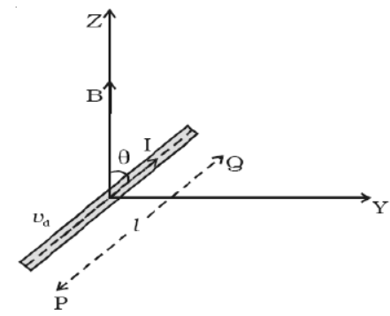
Answer: Consider a conductor of length \( l \) and cross-sectional area \( A \) placed in a uniform magnetic field \( \vec{B} \). If \( n \) is the number density of free electrons, the electric current is given by:
\( I = n A v_d e \)
Multiplying both sides by the length vector \( \vec{l} \) of the conductor (which points in the direction of conventional current):
\( I \vec{l} = -n e A \vec{v}_d l \) --- (1)
The negative sign indicates that the drift velocity of the negative electrons is opposite to the conventional current direction.
The magnetic Lorentz force \( \vec{f} \) acting on a single electron of charge \( -e \) moving with drift velocity \( \vec{v}_d \) is:
\( \vec{f} = -e (\vec{v}_d \times \vec{B}) \) --- (2)
The total number of free electrons inside the conductor is \( N = n A l \) --- (3).
The total force \( \vec{F} \) on the conductor is the sum of the magnetic forces acting on all the free electrons:
\( \vec{F} = N \vec{f} = (n A l) \left[ -e (\vec{v}_d \times \vec{B}) \right] \)
Using equation (1), we can rewrite this as:
\( \vec{F} = I (\vec{l} \times \vec{B}) \).
In scalar form, the magnitude of the force is \( F = I l B \sin\theta \).
In simple words: When a wire carrying current is placed inside a magnetic field, the field exerts a sideways push on all the moving charges. These individual pushes combine to create a macroscopic physical force on the wire.
Exam Tip: Be sure to mention that this force is maximum when the conductor is oriented perpendicular to the magnetic field (\( \theta = 90^\circ \)) and zero when parallel.
Question 8. Force between two long parallel current-carrying conductors
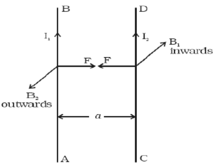
Answer: Let \( AB \) and \( CD \) be two long, straight parallel wires separated by a distance \( a \) in air, carrying currents \( I_1 \) and \( I_2 \) respectively.
The magnetic field \( B_1 \) produced by wire \( AB \) at the location of wire \( CD \) is:
\( B_1 = \frac{\mu_0 I_1}{2\pi a} \)
The magnetic force \( F \) acting on a segment of length \( l \) of wire \( CD \) due to this field is:
\( F = B_1 I_2 l \)
Substituting the value of \( B_1 \):
\( F = \frac{\mu_0 I_1 I_2}{2\pi a} l \).
The force per unit length of the conductor is:
\( \frac{F}{l} = \frac{\mu_0 I_1 I_2}{2\pi a} \).
By applying Fleming's Left Hand Rule, we find that parallel currents attract each other, whereas antiparallel currents repel.
Definition of Ampere:
If \( I_1 = I_2 = 1\text{ A} \), \( a = 1\text{ m} \), and the wires are in a vacuum, then the force per unit length is:
\( \frac{F}{l} = \frac{4\pi \times 10^{-7} \times 1 \times 1}{2\pi \times 1} = 2 \times 10^{-7}\text{ N/m} \).
Hence, one Ampere is defined as that steady current which, when flowing through two parallel, infinitely long straight wires of negligible cross-section placed one meter apart in vacuum, produces a mutual force of \( 2 \times 10^{-7}\text{ Newtons per meter} \) of length.
In simple words: Two parallel wires with current create magnetic fields that push or pull on each other. If the currents flow in the same direction they attract, and if they flow in opposite directions they repel. One ampere is defined by the exact magnetic force these wires exert on each other.
Exam Tip: This derivation is a very common five-mark question. Do not forget to state the conditions of attraction and repulsion based on the direction of currents.
Question 9. Torque experienced by a current loop in a uniform magnetic field
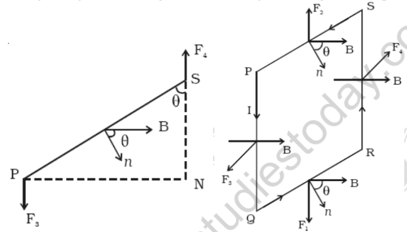
Answer: Consider a rectangular loop \( PQRS \) of length \( l \) and breadth \( b \) carrying a current \( I \) in a uniform magnetic field \( \vec{B} \). Let \( \theta \) be the angle between the normal to the plane of the loop and the magnetic field.
The forces acting on the horizontal sides \( QR \) and \( SP \) are equal and opposite along the same line of action, so their net effect is zero.
The forces on the vertical sides \( PQ \) and \( RS \) (each of magnitude \( F = I l B \)) are equal and opposite but act along different lines of action, forming a torque couple.
The magnitude of this torque \( \tau \) is:
\( \tau = F \times \text{Perpendicular distance between the forces} \)
\( \implies \tau = (I l B) \times (b \sin\theta) \)
Since the area of the loop is \( A = l \cdot b \):
\( \implies \tau = I A B \sin\theta \).
For a coil with \( n \) turns, the torque is:
\( \tau = n I A B \sin\theta \).
We can write this as \( \tau = M B \sin\theta \), where \( M = n I A \) is the magnetic dipole moment of the loop. In vector form, this is:
\( \vec{\tau} = \vec{M} \times \vec{B} \).
In simple words: A current loop placed in a magnetic field experiences equal and opposite forces on its vertical sides. Since these forces are offset, they twist the loop, creating a rotational torque that aligns the loop's magnetic moment with the field.
Exam Tip: Always specify whether \( \theta \) is the angle between the field and the normal to the plane, or the field and the plane itself (where the formula becomes \( \cos\theta \)).
Question 10. Conversion of galvanometer into an ammeter
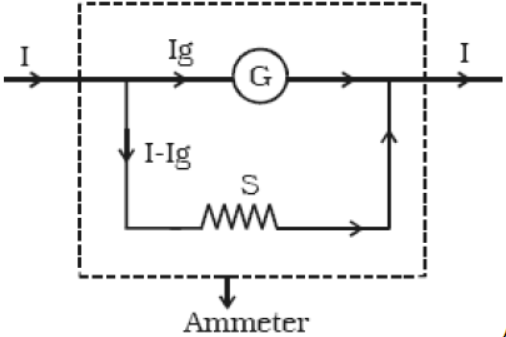
Answer: A galvanometer is converted into an ammeter by connecting a low resistance, known as a shunt resistor \( S \), in parallel with its coil. This low-resistance parallel path allows the major portion of the current to bypass the delicate galvanometer.
Let \( G \) be the galvanometer resistance and \( I_g \) be its maximum deflection current. To measure a total current \( I \), the remaining current \( I - I_g \) must pass through the shunt \( S \).
Since the galvanometer and the shunt are connected in parallel, the potential difference across them is equal:
\( I_g \cdot G = (I - I_g) \cdot S \)
\( \implies S = \frac{I_g G}{I - I_g} \).
The equivalent resistance \( R_a \) of the converted ammeter is given by:
\( R_a = \frac{G S}{G + S} \).
Since the shunt \( S \) is extremely small, the overall resistance of the ammeter is very low, as required for a current-measuring device.
In simple words: To turn a delicate galvanometer into an ammeter that can measure large currents, we connect a very small resistor (a shunt) in parallel. This acts as a bypass lane so that most of the electric current goes through the shunt rather than overloading the meter.
Exam Tip: An ideal ammeter has zero resistance. Explain that the parallel shunt significantly lowers the overall resistance of the galvanometer, making it closer to ideal.
Question 11. Conversion of galvanometer into a voltmeter
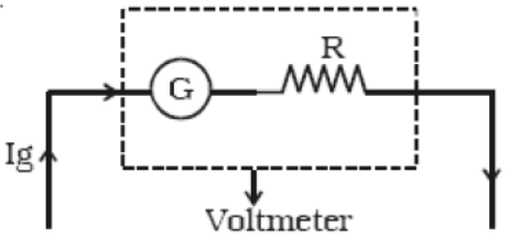
Answer: A galvanometer is converted into a voltmeter by connecting a high resistance \( R \) in series with its coil. This high series resistance limits the current flowing through the device, protecting the galvanometer when connected in parallel across a voltage source.
Let \( G \) be the galvanometer resistance and \( I_g \) be the current required for full-scale deflection. If the voltmeter is designed to measure a maximum potential difference \( V \), the total series resistance is \( R + G \).
According to Ohm's Law:
\( V = I_g (R + G) \)
\( \implies R + G = \frac{V}{I_g} \)
\( \implies R = \frac{V}{I_g} - G \).
The total effective resistance \( R_v \) of the converted voltmeter is:
\( R_v = G + R \).
This high resistance ensures the voltmeter draws negligible current from the main circuit.
In simple words: To convert a galvanometer into a voltmeter, we connect a very large resistor in series with it. This large resistor blocks most of the current, allowing the device to safely measure voltage without draining energy from the circuit.
Exam Tip: State that an ideal voltmeter has infinite resistance. The high series resistor \( R \) is chosen specifically to make the total resistance of the voltmeter extremely high.
Question 12. THE MOVING COIL GALVANOMETER
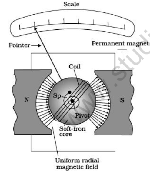
Answer: **Principle:** A current-carrying coil suspended in a magnetic field experiences a deflecting magnetic torque. The resulting angular deflection of the coil is directly proportional to the current flowing through it.
**Working and Derivation:**
When a current \( I \) passes through a coil of \( N \) turns and area \( A \) placed in a magnetic field \( B \), the deflecting torque is given by:
\( \tau = N I A B \sin\theta \)
In a moving coil galvanometer, the magnetic field is made radial using cylindrical pole pieces and a soft iron core. In a radial field, the plane of the coil is always parallel to the field lines (\( \theta = 90^\circ \)), so \( \sin\theta = 1 \):
\( \tau = N I A B \) --- (1)
This deflecting torque is balanced by a restoring spring torque \( \tau_{\text{restoring}} = k \phi \), where \( k \) is the torsional constant of the spring and \( \phi \) is the angular deflection:
\( k \phi = N I A B \)
\( \implies \phi = \left( \frac{N A B}{k} \right) I \).
Since the term in the brackets is constant, the angular deflection is directly proportional to the current (\( \phi \propto I \)).
In simple words: A moving coil galvanometer uses curved magnets to twist a wire coil when current flows through it. A small spring resists this twist, so the needle's movement (deflection) directly shows how much current is flowing.
Exam Tip: Always explain that the cylindrical soft iron core has two key purposes: it makes the magnetic field radial and increases its overall magnetic strength.
Question 12. Bar magnet as an equivalent solenoid
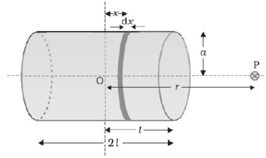
Answer: To show that a current-carrying solenoid behaves like a bar magnet, we calculate its magnetic field at a distant axial point \( P \) at a distance \( r \) from its center.
Let the solenoid have a length \( 2l \), radius \( a \) and \( n \) turns per unit length carrying current \( I \). Consider a small slice of thickness \( dx \) at a distance \( x \) from the center.
The magnetic field \( d B \) at point \( P \) due to this element is:
\( d B = \frac{\mu_0 (n \cdot dx) I a^2}{2 [(r - x)^2 + a^2]^{3/2}} \)
For a very distant point where \( r \gg a \) and \( r \gg l \), we can approximate the denominator as \( r^3 \):
\( d B \approx \frac{\mu_0 n I a^2}{2 r^3} dx \)
Integrating this expression along the entire length of the solenoid from \( -l \) to \( +l \):
\( B = \int_{-l}^{l} \frac{\mu_0 n I a^2}{2 r^3} dx = \frac{\mu_0 n I a^2}{2 r^3} [x]_{-l}^{l} = \frac{\mu_0 n I a^2 (2l)}{2 r^3} \)
Since the total number of turns is \( N = n(2l) \), the total magnetic dipole moment of the solenoid is \( m = N I (\pi a^2) \). Substituting this:
\( B = \frac{\mu_0 2 m}{4\pi r^3} \).
Since this formula is identical to the magnetic field on the axis of a short bar magnet, the current-carrying solenoid is equivalent to a bar magnet.
In simple words: By integrating the magnetic fields of all the circular wire loops in a solenoid, we prove that from a far distance, the solenoid's magnetic field is mathematically identical to that of a bar magnet.
Exam Tip: Ensure you clearly define the total magnetic dipole moment \( m = N I A \) during the final substitution steps of your derivation.
Question 13. Circular current loop as a magnetic dipole
Answer: The magnetic field \( B \) at a distance \( x \) along the axis of a circular current-carrying loop of radius \( R \) is:
\( B = \frac{\mu_0 I R^2}{2 (x^2 + R^2)^{3/2}} \)
For a point far away from the loop where \( x \gg R \), the \( R^2 \) term in the denominator can be neglected:
\( B \approx \frac{\mu_0 I R^2}{2 x^3} \)
Multiplying and dividing the numerator and denominator by \( \pi \):
\( B = \frac{\mu_0 I (\pi R^2)}{2 \pi x^3} = \frac{\mu_0 I A}{2\pi x^3} \)
where \( A = \pi R^2 \) is the area of the circular loop.
Substituting the magnetic dipole moment \( m = I A \):
\( B = \frac{\mu_0 m}{2\pi x^3} = \frac{\mu_0 2 m}{4\pi x^3} \).
Since this matches the axial magnetic field formula of a magnetic dipole, a circular current loop behaves exactly like a magnetic dipole.
In simple words: When viewed from a distance, the magnetic field of a small circular current loop drops off with the cube of the distance, following the exact same mathematical pattern as a magnetic dipole.
Exam Tip: Always remember that the direction of the magnetic dipole moment is determined by the right-hand thumb rule, perpendicular to the plane of the loop.
Free study material for Physics
Free CBSE Practice Worksheets: Class 12 Physics Quick Questions
Daily Practice Questions for Class 12 Physics
Explore reliable practice questions for Quick Questions tailored for Class 12 Physics learners. Use these structured worksheets to evaluate exam preparedness and strengthen problem-solving skills throughout the 2026 academic session.
Detailed Answers for Class 12 Physics Quick Questions
Built using official NCERT guidelines for Class 12 Physics, these practice sheets provide reliable academic support. Cross-reference your completed work with our detailed solutions to learn standard answer-writing formats for CBSE exams.
Complete Your Chapter Revision
Wrap up your chapter revision by testing your knowledge against standard objective question formats. Explore our full library of free, up-to-date printable assignments to maximize your academic results in upcoming CBSE evaluations.
FAQs
You can download the latest chapter-wise printable worksheets for Class 12 Physics Quick Questions for free from StudiesToday.com. These have been made as per the latest CBSE curriculum for this academic year.
Yes, Class 12 Physics worksheets for Quick Questions focus on activity-based learning and also competency-style questions. This helps students to apply theoretical knowledge to practical scenarios.
Yes, we have provided solved worksheets for Class 12 Physics Quick Questions to help students verify their answers instantly.
Yes, our Class 12 Physics test sheets are mobile-friendly PDFs and can be printed by teachers for classroom.
For Quick Questions, regular practice with our worksheets will improve question-handling speed and help students understand all technical terms and diagrams.