
Get the most accurate NCERT Solutions for Class 12 Physics Chapter 6 Electromagnetic Induction here. Updated for the 2026-27 academic session, these solutions are based on the latest NCERT textbooks for Class 12 Physics. Our expert-created answers for Class 12 Physics are available for free download in PDF format.
Detailed Chapter 6 Electromagnetic Induction NCERT Solutions for Class 12 Physics
For Class 12 students, solving NCERT textbook questions is the most effective way to build a strong conceptual foundation. Our Class 12 Physics solutions follow a detailed, step-by-step approach to ensure you understand the logic behind every answer. Practicing these Chapter 6 Electromagnetic Induction solutions will improve your exam performance.
Class 12 Physics Chapter 6 Electromagnetic Induction NCERT Solutions PDF
Question : Predict the direction of induced current in the situations described by the following Figs. 6.18(a) to (f ).
(a)
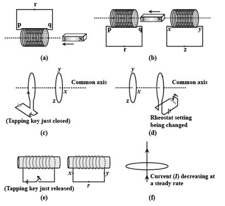
Answer : Lenz’s law shows the direction of induced current in a closed loop. In the given two figures they shows the direction of induced current when the North pole of a bar magnet is moved towards and away from a closed loop respectively.
We can predict the direction induced current in different situation by using the Lenz’s rule.
(i) The direction of the induced current is along qrpq.
(ii) The direction of the induced current is along prqp.
(iii) The direction of the induced current is along yzxy.
(iv) The direction of the induced current is along zyxz.
(v) The direction of the induced current is along xryx.
(vi) No current is induced since the field lines are lying in the plane of the closed loop.
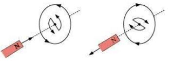
Question : Use Lenz’s law to determine the direction of induced current in the situations described by Fig. 6.19:
(a) A wire of irregular shape turning into a circular shape;
(b) A circular loop being deformed into a narrow straight wire.

Answer : According to Lenz’s law, the direction of the induced emf is such that it tends to produce a current that opposes the change in the magnetic flux that produced it.
(a) When the shape of the wire changes, the flux piercing through the unit surface area increases. As a result, the induced current produces an opposing flux. Hence, the induced current flows along adcb.
(b) When the shape of a circular loop is deformed into a narrow straight wire, the flux piercing the surface decreases. Hence, the induced current flows along adcba
Question : A long solenoid with 15 turns per cm has a small loop of area 2.0 cm2 placed inside the solenoid normal to its axis. If the current carried by the solenoid changes steadily from 2.0 A to 4.0 A in 0.1 s, what is the induced emf in the loop while the current is changing?
Answer : Number of turns on the solenoid = 15 turns/cm = 1500 turns/m
Number of turns per unit length, n = 1500 turns
The solenoid has a small loop of area, A = 2.0 cm2 = 2 × 10⁻⁴ m2
Current carried by the solenoid changes from 2 A to 4 A.
Change in current in the solenoid, di = 4 − 2 = 2 A
Change in time, dt = 0.1s
Induced emf in the solenoid is given by Faraday’s law as:
e = dØ/dt
Where,
Ø= Induced flux through the small loop
= BA ... (ii)
B = Magnetic field
= μ0ni
μ0 = Permeability of free space
= 4π × 10−7 H/m
Hence, equation (i) reduces to:
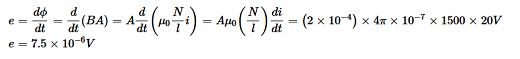
Hence, the induced voltage in the loop is 7.5 x 10⁻⁶ v
Question : A rectangular wire loop of sides 8 cm and 2 cm with a small cut is moving out of a region of uniform magnetic field of magnitude 0.3 T directed normal to the loop. What is the emf developed across the cut if the velocity of the loop is 1 cm s−1 in a direction normal to the (a) longer side, (b) shorter side of the loop? For how long does the induced voltage last in each case?
Answer : Length of the rectangular wire, l = 8 cm = 0.08 m
Width of the rectangular wire, b = 2 cm = 0.02 m
Hence, area of the rectangular loop,
A = lb
= 0.08 × 0.02
= 16 × 10−4 m2
Magnetic field strength, B = 0.3 T
Velocity of the loop, v = 1 cm/s = 0.01 m/s
(a) Emf developed in the loop is given as:
e = Blv
= 0.3 × 0.08 × 0.01 = 2.4 × 10⁻⁴ V
![]()
= 0.02/0.01 = 2s
Hence, the induced voltage is 2.4 × 10⁻⁴ V which lasts for 2 s.
(b) Emf developed, e = Bbv
= 0.3 × 0.02 × 0.01 = 0.6 × 10⁻⁴ V
![]()
= 0.08/0.01 = 8s
Hence, the induced voltage is 0.6 × 10⁻⁴ V which lasts for 8 s.
Question : A 1.0 m long metallic rod is rotated with an angular frequency of 400 rad s−1 about an axis normal to the rod passing through its one end. The other end of the rod is in contact with a circular metallic ring. A constant and uniform magnetic field of 0.5 T parallel to the axis exists everywhere. Calculate the emf developed between the centre and the ring.
Answer : Length of the rod, l = 1 m
Angular frequency,ω = 400 rad/s
Magnetic field strength, B = 0.5 T
One end of the rod has zero linear velocity, while the other end has a linear velocity of lω.
Average linear velocity of the rod, V = lω + 0 / 2 = lω /2
Emf developed between the centre and the ring,
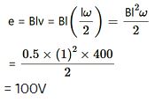
Hence, the emf developed between the centre and the ring is 100 V.
Question : A circular coil of radius 8.0 cm and 20 turns is rotated about its vertical diameter with an angular speed of 50 rad s−1 in a uniform horizontal magnetic field of magnitude 3.0 × 10⁻² T. Obtain the maximum and average emf induced in the coil. If the coil forms a closed loop of resistance 10Ω, calculate the maximum value of current in the coil. Calculate the average power loss due to Joule heating. Where does this power come from?
Answer : Max induced emf = 0.603 V
Average induced emf = 0 V
Max current in the coil = 0.0603 A
Average power loss = 0.018 W
(Power comes from the external rotor)
Radius of the circular coil, r = 8 cm = 0.08 m
Area of the coil, A = πr2 = π × (0.08)2 m2
Number of turns on the coil, N = 20
Angular speed, ω = 50 rad/s
Magnetic field strength, B = 3 × 10⁻² T
Resistance of the loop, R = 10 Ω
Maximum induced emf is given as:
e = Nω AB
= 20 × 50 × π × (0.08)2 × 3 × 10−2
= 0.603 V
The maximum emf induced in the coil is 0.603 V.
Over a full cycle, the average emf induced in the coil is zero.
Maximum current is given as:
I = e/R
= 0.603/10 = 0.0603
Average power loss due to joule heating:
P = eI/2
= 0.603 x 0.0603/2 = 0.018W
The current induced in the coil produces a torque opposing the rotation of the coil. The rotor is an external agent. It must supply a torque to counter this torque in order to keep the coil rotating uniformly. Hence, dissipated power comes from the external rotor.
Question : A horizontal straight wire 10 m long extending from east to west is falling with a speed of 5.0 m s−1, at right angles to the horizontal component of the earth’s magnetic field, 0.30 × 10⁻⁴ Wb m−2.
(a) What is the instantaneous value of the emf induced in the wire?
(b) What is the direction of the emf?
(c) Which end of the wire is at the higher electrical potential?
Answer : Wire’s Length, l = 10 m
Speed of the wire with which it is falling, v = 5.0 m/s
Strength of magnetic field, B = 0.3×10⁻⁴ Wbm−2
(a) EMF induced in the wire, e = Blv
= 0.3×10−4×5×10=1.5×10⁻³V
(b) We can determine the direction of the induced current by using the Fleming’s right hand thumb rule, here the current is flowing in the direction from West to East.
(c) In this case the eastern end of the wire will be having higher potential
Question : Current in a circuit falls from 5.0 A to 0.0 A in 0.1 s. If an average emf of 200 V induced, give an estimate of the self-inductance of the circuit.
Answer : Initial current, I1 = 5.0 A
Final current, I2 = 0.0 A
Change in current,dl = I1 - I2 = 5A
Time taken for the change, t = 0.1 s
Average emf, e = 200 V
For self-inductance (L) of the coil, we have the relation for average emf as:
e = L di/dt
L = e/(di/dt)
200/(5/0.1) = 4H
Hence, the self induction of the coil is 4 H.
Question : A pair of adjacent coils has a mutual inductance of 1.5 H. If the current in one coil changes from 0 to 20 A in 0.5 s, what is the change of flux linkage with the other coil?Answer : Given, a pair of adjacent coils.
Mutual inductance, M = 1.5 H
Current in the coil, I = 20 A
Time ,t = 0.5 s
Using formula, Φ = MI we get,
Φ = 1.5 x 20 = 30H
Hence, the change in the flux linkage is 30 Wb.
Question : Calculate the difference in voltage developed between two ends of a jet plane, when the jet plane is travelling towards west with a speed of 1800 km/h and the wing of the plane is having a span of 25 m. We are given that the earth’s magnetic field are the location has a magnitude of 5×10⁻⁴T and the dip angle is 300.
Answer : Speed of the plane with which it is moving, v = 1800 km/h = 500 m/s
Wing span of the jet, l = 25 m
Magnetic field strength by earth, B = 5 × 10⁻⁴T
Dip angle, δ = 30∘
Vertical component of Earth’s magnetic field,
Bv=Bsin δ=5 ×10⁻⁴ sin30 ∘ = 2.5 × 10− 4T
Difference in voltage between both the ends can be calculated as:
e = (Bv)× l × v = 2.5 × × 10− 4 ×25 ×500 = 3.123V
Hence, the voltage difference developed between the ends of the wings is 3.125 V.
Question : Suppose the loop in Exercise 6.4 is stationary but the current feeding the electromagnet that produces the magnetic field is gradually reduced so that the field decreases from its initial value of 0.3 T at the rate of 0.02 T s−1. If the cut is joined and the loop has a resistance of 1.6 Ω how much power is dissipated by the loop as heat? What is the source of this power?
Answer : Sides of the rectangular loop are 8 cm and 2 cm.
Hence, area of the rectangular wire loop,
A = length × width
= 8 × 2 = 16 cm2
= 16 × 10−4 m2
Initial value of the magnetic field, B' = 0.3 T
Rate of decrease of the magnetic field, dB/dt = 0.02T/s
Emf developed in the loop is given as:
e = dΦ/dt
Where,
dΦ = Change in flux through the loop area = AB
∴ e = d(AB)/dt = AdB/dt
Resistance of the loop, R = 1.6 Ω
The current induced in the loop is given as:
i = e/R
= 0.32 x 10⁻⁴/1.6
Power dissipated in the loop in the form of heat is given as:
P = i²R
= (2 × 10-5) x 1.6
= 6.4 x 10⁻¹⁰ W
The source of this heat loss is an external agent, which is responsible for changing the magnetic field with time.
Question : A square loop of side 12 cm with its sides parallel to X and Y axes is moved with a velocity of 8 cm s−1 in the positive x-direction in an environment containing a magnetic field in the positive z-direction. The field is neither uniform in space nor constant in time. It has a gradient of 10−3 T cm−1 along the negative x-direction (that is it increases by 10− 3 T cm−1 as one moves in the negative x-direction), and it is decreasing in time at the rate of 10−3 T s−1. Determine the direction and magnitude of the induced current in the loop if its resistance is 4.50 mΩ.
Answer : Side of the square loop, s = 12 cm = 0.12 m
Area of the square loop, A = 0.12 × 0.12 = 0.0144 m2
Velocity of the loop, v = 8 cm/s = 0.08 m/s
Gradient of the magnetic field along negative x-direction,
dB/dx = 10-3 T cm-1 = 10-1 Tm-1
And, rate of decrease of the magnetic field,
dB/dt = 10-1 T s-1
R = 4.5 mΩ = 4.5 x 10⁻³Ω
Rate of change of the magnetic flux due to the motion of the loop in a non-uniform magnetic field is given as:
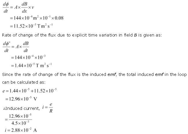
Hence, the direction of the induced current is such that there is an increase in the flux through the loop along positive z-direction.
Question : It is desired to measure the magnitude of field between the poles of a powerful loud speaker magnet. A small flat search coil of area 2 cm2 with 25 closely wound turns, is positioned normal to the field direction, and then quickly snatched out of the field region. Equivalently, one can give it a quick 90° turn to bring its plane parallel to the field direction). The total charge flown in the coil (measured by a ballistic galvanometer connected to coil) is 7.5 mC. The combined resistance of the coil and the galvanometer
is 0.50 ?. Estimate the field strength of magnet.
Answer : Area of the small flat search coil, A = 2 cm2 = 2 × 10⁻⁴ m2
Number of turns on the coil, N = 25
Total charge flowing in the coil, Q = 7.5 mC = 7.5 × 10⁻³ C
Total resistance of the coil and galvanometer, R = 0.50 ?
Induced current in the coil,
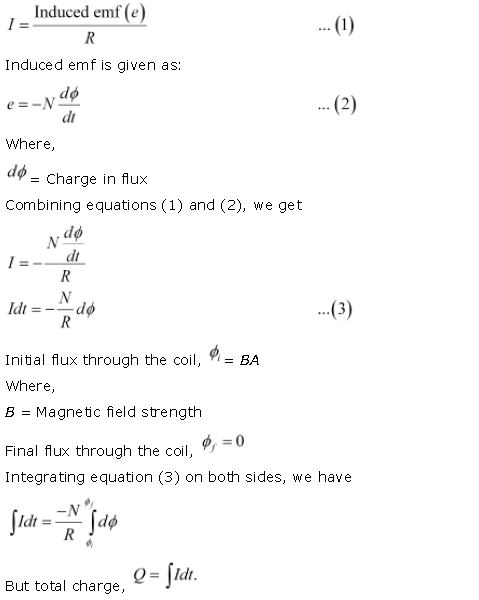
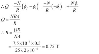
Hence, the field strength of the magnet is 0.75 T.
Question : Figure 6.20 shows a metal rod PQ resting on the smooth rails AB and positioned between the poles of a permanent magnet. The rails, the rod, and the magnetic field are in three mutual perpendicular directions. A galvanometer G connects the rails through a switch K. Length of the rod = 15 cm, B = 0.50 T, resistance of the closed loop containing the rod = 9.0 m?. Assume the field to be uniform.
(a) Suppose K is open and the rod is moved with a speed of 12 cm s−1 in the direction shown. Give the polarity and magnitude of the induced emf.
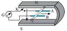
(b) Is there an excess charge built up at the ends of the rods when K is open? What if K is closed?
(c) With K open and the rod moving uniformly, there is no net force on the electrons in the rod PQ even though they do experience magnetic force due to the motion of the rod. Explain.
(d) What is the retarding force on the rod when K is closed?
(e) How much power is required (by an external agent) to keep the rod moving at the same speed (=12 cm s−1) when K is closed? How much power is required when K is open?
(f) How much power is dissipated as heat in the closed circuit?
What is the source of this power?
(g) What is the induced emf in the moving rod if the magnetic field is parallel to the rails instead of being perpendicular?
Answer : Length of the rod, l = 15 cm = 0.15 m
Magnetic field strength, B = 0.50 T
Resistance of the closed loop, R = 9 m? = 9 × 10⁻³ ?
(a) Induced emf = 9 mV; polarity of the induced emf is such that end P shows positive while end Q shows negative ends.
Speed of the rod, v = 12 cm/s = 0.12 m/s
Induced emf is given as:
e = Bvl
= 0.5 × 0.12 × 0.15
= 9 × 10⁻³ v
= 9 mV
The polarity of the induced emf is such that end P shows positive while end Q shows negative ends.
(b) Yes; when key K is closed, excess charge is maintained by the continuous flow of current.
When key K is open, there is excess charge built up at both ends of the rods.
When key K is closed, excess charge is maintained by the continuous flow of current.
(c) Magnetic force is cancelled by the electric force set-up due to the excess charge of opposite nature at both ends of the rod.
There is no net force on the electrons in rod PQ when key K is open and the rod is moving uniformly. This is because magnetic force is cancelled by the electric force set-up due to the excess charge of opposite nature at both ends of the rods.
(d) Retarding force exerted on the rod, F = IBl
Where,
I = Current flowing through the rod
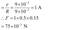
(e) 9 mW; no power is expended when key K is open.
Speed of the rod, v = 12 cm/s = 0.12 m/s
Hence, power is given as
P = Fv
= 75 x 10-3 x 0.12
= 9 x 10⁻³ W
= 9 mW
When key K is open, no power is expended.
(f) 9 mW; power is provided by an external agent.
Power dissipated as heat = I2 R
= (1)2 × 9 × 10−3
= 9 mW
The source of this power is an external agent.
(g) Zero
In this case, no emf is induced in the coil because the motion of the rod does not cut across the field lines.
Question : An air-cored solenoid with length 30 cm, area of cross-section 25 cm2 and number of turns 500, carries a current of 2.5 A. The current is suddenly switched off in a brief time of 10−3 s. How much is the average back emf induced across the ends of the open switch in the circuit? Ignore the variation in magnetic field near the ends of the solenoid.
Answer : Length of the solenoid, l = 30 cm = 0.3 m
Area of cross-section, A = 25 cm2 = 25 × 10−4 m2
Number of turns on the solenoid, N = 500
Current in the solenoid, I = 2.5 A
Current flows for time, t = 10−3 s
Average back emf, e = dΦ/dt
Where,
dΦ = Change in flux
= NAB … (2)
Where,
B = Magnetic field strength
= μo NI/l
Where,
μo = Permeability of free space = 4π × 10−7 T m A−1
Using equations (2) and (3) in equation (1), we get
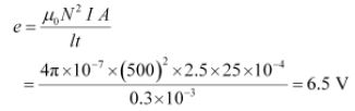
Hence, the average back emf induced in the solenoid is 6.5 V.
Question : (a) Obtain an expression for the mutual inductance between a long straight wire and a square loop of side a as shown in Fig. 6.21.
(b) Now assume that the straight wire carries a current of 50 A and the loop is moved to the right with a constant velocity, v = 10 m/s.
Calculate the induced emf in the loop at the instant when x = 0.2 m.
Take a = 0.1 m and assume that the loop has a large resistance.
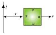
Answer : (a) Take a small element dy in the loop at a distance y from the long straight wire (as shown in the given figure).
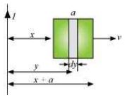
Magnetic flux associated with element dy, dΦ = BdA
Where,
dA = Area of element dy = a dy
B = Magnetic field at distance y
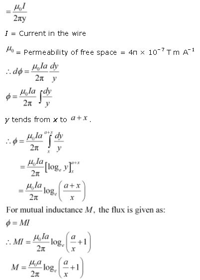
(b) Emf induced in the loop, e = B’av = (μoI/2πx)av
Given,
I = 50 A
x = 0.2 m
a = 0.1 m
v = 10 m/s
e = 4π x 10-7 x 50 x 0.1 x 10 / 2π x 0.2
e = 5 x 10⁻⁵ V
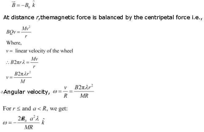
Question : A line charge λ per unit length is lodged uniformly onto the rim of a wheel of mass M and radius R. The wheel has light non-conducting spokes and is free to rotate without friction about its axis (Fig. 6.22). A uniform magnetic field extends over a circular region within the rim. It is given by,
B = − B0 k (r ≤ a; a < R)
= 0 (otherwise)
What is the angular velocity of the wheel after the field is suddenly switched off?
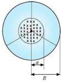
Answer : Line charge per unit length
![]()
Where,
r = Distance of the point within the wheel
Mass of the wheel = M
Radius of the wheel = R
Magnetic field,
Free study material for Physics
NCERT Solutions Class 12 Physics Chapter 6 Electromagnetic Induction
Students can now access the NCERT Solutions for Chapter 6 Electromagnetic Induction prepared by teachers on our website. These solutions cover all questions in exercise in your Class 12 Physics textbook. Each answer is updated based on the current academic session as per the latest NCERT syllabus.
Detailed Explanations for Chapter 6 Electromagnetic Induction
Our expert teachers have provided step-by-step explanations for all the difficult questions in the Class 12 Physics chapter. Along with the final answers, we have also explained the concept behind it to help you build stronger understanding of each topic. This will be really helpful for Class 12 students who want to understand both theoretical and practical questions. By studying these NCERT Questions and Answers your basic concepts will improve a lot.
Benefits of using Physics Class 12 Solved Papers
Using our Physics solutions regularly students will be able to improve their logical thinking and problem-solving speed. These Class 12 solutions are a guide for self-study and homework assistance. Along with the chapter-wise solutions, you should also refer to our Revision Notes and Sample Papers for Chapter 6 Electromagnetic Induction to get a complete preparation experience.
FAQs
The complete and updated is available for free on StudiesToday.com. These solutions for Class 12 Physics are as per latest NCERT curriculum.
Yes, our experts have revised the as per 2026 exam pattern. All textbook exercises have been solved and have added explanation about how the Physics concepts are applied in case-study and assertion-reasoning questions.
Toppers recommend using NCERT language because NCERT marking schemes are strictly based on textbook definitions. Our will help students to get full marks in the theory paper.
Yes, we provide bilingual support for Class 12 Physics. You can access in both English and Hindi medium.
Yes, you can download the entire in printable PDF format for offline study on any device.