
Get the most accurate NCERT Solutions for Class 12 Physics Chapter 3 Current Electricity here. Updated for the 2026-27 academic session, these solutions are based on the latest NCERT textbooks for Class 12 Physics. Our expert-created answers for Class 12 Physics are available for free download in PDF format.
Detailed Chapter 3 Current Electricity NCERT Solutions for Class 12 Physics
For Class 12 students, solving NCERT textbook questions is the most effective way to build a strong conceptual foundation. Our Class 12 Physics solutions follow a detailed, step-by-step approach to ensure you understand the logic behind every answer. Practicing these Chapter 3 Current Electricity solutions will improve your exam performance.
Class 12 Physics Chapter 3 Current Electricity NCERT Solutions PDF
Question. The storage battery of a car has an emf of 12 V. If the internal resistance of the battery is 0.4Ω, what is the maximum current that can be drawn from the battery?
Answer : Given that Emf of the battery, E = 12 V
Battery has an Internal resistance of R = 0.4 Ω
The Maximum current drawn from the battery is given by = I
According to Ohm’s law,
E = IR
I=E / R I=12/0.4 = 30 A
The maximum current drawn from the given battery is 30 A.
Question. A battery of emf 10 V and internal resistance 3 Ω is connected to a resistor. If the current in the circuit is 0.5 A, what is the resistance of the resistor? What is the terminal voltage of the battery when the circuit is closed?
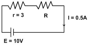
Answer : Electromotive force (E) of battery = 10 volt.
Internal Resistance r of the battery = 3 Ω
Current in the Circuit (I) = 0.5 A
Let the resistance of the required resistor is R Ω
Let the Terminal voltage of the register be V.
As per Ω ’s law,
⇒ I = E/r+R
⇒ R+r= I
⇒ R+ r = 10/0.5
⇒ R + r = 20Ω
∴ r = 3Ω
Resistance of Resistor is 17 Ω
Also, as per Ohm's law,
⇒V = IR
⇒ V = 0.5A x 17Ω =
⇒ V = 8.5V
Terminal voltage of the register is 8.5V.
Question. (a) Three resistors 1 Ω, 2 Ω, and 3 Ω are combined in series. What is the total resistance of the combination?
(b) If the combination is connected to a battery of emf 12 V and negligible internal resistance, obtain the potential drop across each resistor.
Answer : (a) Three resistors of resistances 1 Ω, 2 Ω, and 3 Ω are combined in series. Total resistance of the combination is given by the algebraic sum of individual resistances.
Total resistance = 1 + 2 + 3 = 6 Ω
(b) Current flowing through the circuit = I
Emf of the battery, E = 12 V
Total resistance of the circuit, R = 6 Ω
The relation for current using Ohm’s law is,
I = E/R
= 12/6 = 2 A
Potential drop across 1 Ω resistor = V1
From Ohm’s law, the value of V1 can be obtained as
V1 = 2 × 1 = 2 V … (i)
Potential drop across 2 Ω resistor = V2
Again, from Ohm’s law, the value of V2 can be obtained as
V2 = 2 × 2 = 4 V … (ii)
Potential drop across 3 Ω resistor = V3
Again, from Ohm’s law, the value of V3 can be obtained as
V3 = 2 × 3= 6 V … (iii)
Therefore, the potential drop across 1 Ω, 2 Ω, and 3 Ω resistors are 2 V, 4 V, and 6 V respectively.
Question. (a) Three resistors 2 Ω, 4 Ω and 5 Ω are combined in parallel. What is the total resistance of the combination?
(b) If the combination is connected to a battery of emf 20 V and negligible internal resistance, determine the current through each resistor, and the total current drawn from the battery.
Answer : (a) There are three resistors of resistances,
R1 = 2 Ω, R2 = 4 Ω, and R3 = 5 Ω
They are connected in parallel. Hence, total resistance (R) of the combination is given by,
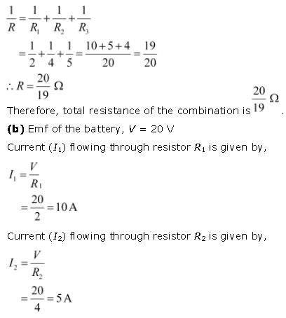
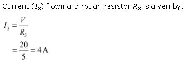
Total current, I = I1 + I2 + I3 = 10 + 5 + 4 = 19 A
Therefore, the current through each resister is 10 A, 5 A, and 4 A respectively and the total current is 19 A.
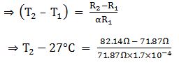
Question. At room temperature (27.0 °C) the resistance of a heating element is 100Ω. What is the temperature of the element if the resistance is found to be 117Ω, given that the temperature coefficient of the material of the resistor is 1.70 × 10⁻⁴ °C–1.
Answer : Given: Temperature coefficient of filament,
α = 1.70 × 10⁻⁴ per °C
Let T1 be the temperature of element, R1 = 100Ω (Given: T1 = 27°C)
Let T2 be the temperature of element, R2 = 117Ω
To find T2 = ?
The formula is: R2 = R1[1 + α(T2-T1)]
⇒ R2 - R1 = R1α(T2 - T1)
⇒ R2 - R1 = R1α (T2 - T1)
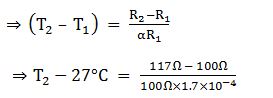
T2 -27°C = 1000°C
T2 1000°C + 27°C
Hence Temperature of element, T2 is 1027 °C.
Question. A negligibly small current is passed through a wire of length 15 m and uniform cross-section 6.0 × 10⁻⁷ m2, and its resistance is measured to be 5.0 Ω. What is the resistivity of the material at the temperature of the experiment?
Answer : Given, the length of wire l = 15 metre
Area of cross section of wire a = 6.0 × 10⁻⁷ metre square
Resistance of material of wire,R = 5 Ω
Resistivity of material of wire = ρ
R = pI/a
⇒ p = Ra/I
⇒ p = 5Ω x 6 x 10-7 m2/15m
⇒ p = 2 x 10⁻⁷Ω - m
Hence Resistivity of material of wire is 2 x 10⁻⁷ metre
Question. A silver wire has a resistance of 2.1 Ω at 27.5 °C, and a resistance of 2.7 Ω at 100 °C.
Determine the temperature coefficient of resistivity of silver.
Answer : Temperature, T1 = 27.5°C
Resistance of the silver wire at T1, R1 = 2.1 Ω
Temperature, T2 = 100°C
Resistance of the silver wire at T2, R2 = 2.7 Ω
Temperature coefficient of silver = α
It is related with temperature and resistance as

Therefore, the temperature coefficient of silver is 0.0039°C−1.
Question. Aheating element using nichrome connected to a 230 V supply draws an initial current of 3.2 A which settles after a few seconds toa steady value of 2.8 A. What is the steady temperature of the heating element if the room temperature is 27.0 °C? Temperature coefficient of resistance of nichrome averaged over the temperature range involved is 1.70 × 10⁻⁴ °C −1.
Answer : Given Supply Voltage = 230 Volt
And it draws current I1 = 3.2 Ampere
Resistance is given by R1 = V/I
R1 = 230V/3.2A
R1 = 71.87 Ω
Steady value of current I2 = 2.8Ampere
Resistance R α is given by R2 = 230V/2.8A
R2 = 82.14 Ω
Temperature coefficient of nichrome wire α = 1.70 × 10⁻⁴ per °C
Initial temperature of nichrome T1 = 27 ° C
Steady Temperature attained by nichrome = T2
The formula is: R2 = R1[1 + α(T2-T1)]
⇒ R2 - R1 = R1α(T2 - T1)
⇒ R2 - R1 = R1α (T2 - T1)
T2 -27°C = 840.5 °C
T2 840.5 °C + 27°C = 867.5° C
Hence Steady Temperature attained by nichrome 867.5° C.
Question. Determine the current in each branch of the network shown in fig 3.30:
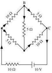
Answer : Current flowing through various branches of the circuit is represented in the given figure.

For the closed circuit ABDA, potential is zero i.e.,
10I2 + 5I4 − 5I3 = 0
2I2 + I4 −I3 = 0
I3 = 2I2 + I4 ... (1)
For the closed circuit BCDB, potential is zero i.e.,
5(I2 − I4) − 10(I3 + I4) − 5I4 = 0
5I2 + 5I4 − 10I3 − 10I4 − 5I4 = 0
5I2 − 10I3 − 20I4 = 0
I2 = 2I3 + 4I4 ... (2)
For the closed circuit ABCFEA, potential is zero i.e.,
−10 + 10 (I1) + 10(I2) + 5(I2 − I4) = 0
10 = 15I2 + 10I1 − 5I4
3I2 + 2I1 − I4 = 2 ... (3)
From equations (1) and (2), we obtain
I3 = 2(2I3 + 4I4) + I4
I3 = 4I3 + 8I4 + I4
− 3I3 = 9I4
− 3I4 = + I3 ... (4)
Putting equation (4) in equation (1), we obtain
I3 = 2I2 + I4
− 4I4 = 2I2
I2 = − 2I4 ... (5)
It is evident from the given figure that,
I1 = I3 + I2 ... (6)
Putting equation (6) in equation (1), we obtain
3I2 + 2(I3 + I2) − I4 = 2
5I2 + 2I3 − I4 = 2 ... (7)
Putting equations (4) and (5) in equation (7), we obtain
5(−2 I4) + 2(− 3 I4) − I4 = 2
− 10I4 − 6I4 − I4 = 2
17I4 = − 2
I4 = -2/17Ampere
Equation (4) reduces to
I3 = − 3(I4)
I3 = -3 × -2/17
I3 = 6/17Ampere
I2 = -2(I4)
I2 = -2 × -2/17
I2 = 4/17Ampere
I2 - I4 = 6/17Ampere
I3 + I4 = 6/17Ampere
I1 = I2 + I3 = 4/17 + 6/17 = 10/17 Ampere
Therefore, current in branch AB = 4/17Ampere
In branch BC = 6/17Ampere
In branch CD = -4/17Ampere
In branch AD = 6/17Ampere
In branch BD = -2/17Ampere
Total current = 4/17 + 6/17 + -4/17 + 6/17 + -2/17 = 10/17Ampere.
Question. (a) In a metre bridge [Fig. 3.27], the balance point is found to be at 39.5 cm from the end A, when the resistor Y is of 12.5 Ω. Determine the resistance of X. Why are the connections between resistors in a Wheatstone or meter bridge made of thick copper strips?
(b) Determine the balance point of the bridge above if X and Y are interchanged.
(c) What happens if the galvanometer and cell are interchanged at the balance point of the bridge? Would the galvanometer show any current?
Answer : The diagram is shown below:
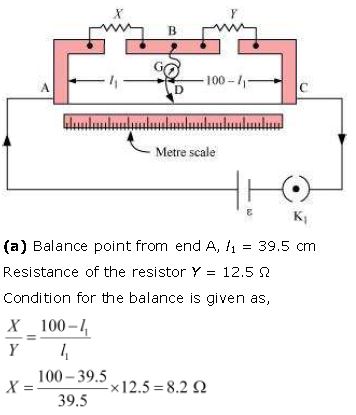
Therefore, the resistance of resistor X is 8.2 Ω.
The connection between resistors in a Wheatstone or metre bridge is made of thick copper strips to minimize the resistance, which is not taken into consideration in the bridge formula.
(b) If X and Y are interchanged, then l1 and 100−l1 get interchanged.
The balance point of the bridge will be 100−l1 from A.
100−l1 = 100 − 39.5 = 60.5 cm
Therefore, the balance point is 60.5 cm from A.
(c) When the galvanometer and cell are interchanged at the balance point of the bridge, the galvanometer will show no deflection. Hence, no current would flow through the galvanometer.
Question. A storage battery of emf 8.0 V and internal resistance 0.5 Ω is being charged by a 120 V dc supply using a series resistor of 15.5 Ω. What is the terminal voltage of the battery during charging? What is the purpose of having a series resistor in the charging circuit?
Answer : Emf of the storage battery, E = 8.0 V
Internal resistance of the battery, r = 0.5 Ω
DC supply voltage, V = 120 V
Resistance of the resistor, R = 15.5 Ω
Effective voltage in the circuit = V1
R is connected to the storage battery in series. Hence, it can be written as
V1 = V − E
V1 = 120 − 8 = 112 V
Current flowing in the circuit = I, which is given by the relation,
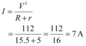
Voltage across resistor R given by the product, IR = 7 × 15.5 = 108.5 V
DC supply voltage = Terminal voltage of battery + Voltage drop across R
Terminal voltage of battery = 120 − 108.5 = 11.5 V
A series resistor in a charging circuit limits the current drawn from the external source.
The current will be extremely high in its absence. This is very dangerous.
Question. In a potentiometer arrangement, a cell of emf 1.25 V gives a balance point at 35.0 cm length of the wire. If the cell is replaced by another cell and the balance point shifts to 63.0 cm, what is the emf of the second cell?
Answer : Given EMF of the cell E1 = 1.25Volt
Balance point of the potentiometer l1 is given 35cm
Since the cell is replaced by another cell of EMF E2
New balance point of potentiometer l2 is 63cm
Since balance condition is given by E1 / E2 = I1 / I2
⇒ E2 = E1 X = I1 / I2
E2 = 1.25V x (63m/35m)
E2 = 2.25Volt.
Question. The number density of free electrons in a copper conductor estimated in Example 3.1 is 8.5 × 1028 m−3. How long does an electron take to drift from one end of a wire 3.0 m long to its other end? The area of cross-section of the wire is 2.0 × 10⁻⁶ m2 and it is carrying a current of 3.0 A.
Answer : Number density of free electrons in a copper conductor, n = 8.5 × 1028 m−3 Length of the copper wire, l = 3.0 m
Area of cross-section of the wire, A = 2.0 × 10⁻⁶ m2
Current carried by the wire, I = 3.0 A, which is given by the relation,
I = nAeVd
Where,
e = Electric charge = 1.6 × 10⁻¹⁹ C
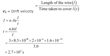
Therefore, the time taken by an electron to drift from one end of the wire to the other is 2.7 × 10⁴ s.
Question. The earth’s surface has a negative surface charge density of 10−9 C m−2. The potential difference of 400 kV between the top of the atmosphere and the surface results (due to the low conductivity of the lower atmosphere) in a current of only 1800 A over the entire globe. If there were no mechanism of sustaining atmospheric electric field, how much time (roughly) would be required to neutralise the earth’s surface? (This never happens in practice because there is a mechanism to replenish electric charges, namely the continual thunderstorms and lightning in different parts of the globe). (Radius of earth = 6.37 × 10⁶ m.)
Answer : Surface Charge density of earth d = 10-9 Coulomb per meter square
Current over the entire globe = 1800 Ampere
Radius of earth r = 6.37 × 10⁶ meter
Surface area of earth A = 4×π×radius×radius
A = 4×π×6.37×106×6.37×106
A = 5.09 × 10¹⁴ m2
Charge on the earth surface q = d × A
q = 10-9 × 5.09 ×1014 m2
q = 5.09 × 10⁵ Coulomb
Let the time taken to neutralize earth surface = t
Current I = q/t
⇒ t = q/I
t = 5.09 x 10⁵C/1800 A
t = 282.78 seconds.
Question. Two wires of equal length, one of aluminium and the other of copper have the same resistance. Which of the two wires is lighter? Hence explain why aluminium wires are preferred for overhead power cables. (ρAl = 2.63 × 10⁻⁸ Ω m, ρCu = 1.72 × 10⁻⁸ Ω m, Relative density of Al = 2.7, of Cu = 8.9.)
Answer : Resistivity of aluminium, p1 = 2.63 × 10⁻⁸ Ω m
Relative density of aluminium, d1 = 2.7
Let l1 be the length of aluminium wire and m1 be its mass.
Resistance of the aluminium wire = R1
Area of cross-section of the aluminium wire = A1
Resistivity of copper, p2 = 1.72 × 10⁻⁸ Ω metre
Relative density of copper, d2 = 8.9
Let l2 be the length of copper wire and m2 be its mass.
Resistance of the copper wire = R2
Area of cross-section of the copper wire = A2
We can write,
R1 = (p1 × l1)/A1
R2 = (p2 × l2)/A2
Since R1 = R2
(p1 × l1)/A1 = (p2 × l2)/A2
And l1 = l2
Therefore p1/A1 = p2/A2
A1/A2 = (2.63 × 10⁻⁸)/(1.72 × 10-8)
⇒ A1/A2 = 2.63/1.72
Mass of the aluminium wire,
m1 = Volume × Density
= A1 × l1 × d1 = A1 l1 d1 .....1
Mass of the copper wire, m2 = Volume × Density
= A2 × l2 × d2 = A2 l2 d2 .......2
Dividing equation (1) by equation (2), we obtain
m1/m2 = (A1 l1 d1)/(A2 l2 d2)
Since l1 = l2
m1/m2 = A1 d1/A2 d2
Since A1/A2 = 2.63/1.72 calculated above
⇒ m1/m2 = (2.63 × 2.7)/(1.72 × 8.9)
⇒ m1/m2 = 0.46
It can be inferred from this ratio that m1 is less than m2. Hence, aluminium is lighter than copper.
Since aluminium is lighter, it is preferred for overhead power cables over copper.
Question. What conclusion can you draw from the following observations on a resistor made of alloy manganin?

Answer : It can be inferred from the given table that the ratio of voltage with current is a constant, which is equal to 19.7. Hence, manganin is an ohmic conductor i.e., the alloy obeys Ohm’s law. According to Ohm’s law, the ratio of voltage with current is the resistance of the conductor. Hence, the resistance of manganin is 19.7 Ω.
Question. Answer the following questions:
(a) A steady current flows in a metallic conductor of non-uniform cross- section. Which of these quantities is constant along the conductor: current, current density, electric field, drift speed?
(b) Is Ohm’s law universally applicable for all conducting elements?
If not, give examples of elements which do not obey Ohm’s law.
(c) A low voltage supply from which one needs high currents must have very low internal resistance. Why?
(d) A high tension (HT) supply of, say, 6 kV must have a very large internal resistance. Why?
Answer : (a) When a steady current flows in a metallic conductor of non-uniform cross-section, the current flowing through the conductor is constant. Current density, electric field, and drift speed are inversely proportional to the area of cross-section. Therefore, they are not constant.
(b) No, Ohm’s law is not universally applicable for all conducting elements. Vacuum diode semi-conductor is a non-ohmic conductor. Ohm’s law is not valid for it.
(c) According to Ω ’s law V = I×R
If Voltage V is low, then Resistance R must be very low so that high current can be drawn from source.
(d) In order to prohibit the current from exceeding the safety limit, a high tension supply must have a very large internal resistance. If the internal resistance is not large, then the current drawn can exceed the safety limits in case of a short circuit.
Question. Choose the correct alternative:
(a) Alloys of metals usually have (greater/less) resistivity than that of their constituent metals.
(b) Alloys usually have much (lower/higher) temperature coefficients of resistance than pure metals.
(c) The resistivity of the alloy manganin is nearly independent of/increases rapidly with increase of temperature.
(d) The resistivity of a typical insulator (e.g., amber) is greater than that of a metal by a factor of the order of (1022/103).
Answer : (a) Alloys of metals usually have greater resistivity than that of their constituent metals.
(b) Alloys usually have lower temperature coefficients of resistance than pure metals.
(c) The resistivity of the alloy, manganin, is nearly independent of increase of temperature.
(d) The resistivity of a typical insulator is greater than that of a metal by a factor of the order of 1022.
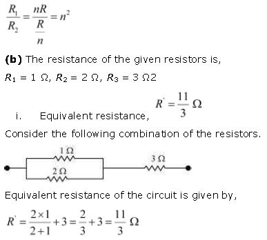
Question. (a) Given n resistors each of resistance R, how will you combine them to get the (i) maximum (ii) minimum effective resistance? What is the ratio of the maximum to minimum resistance?
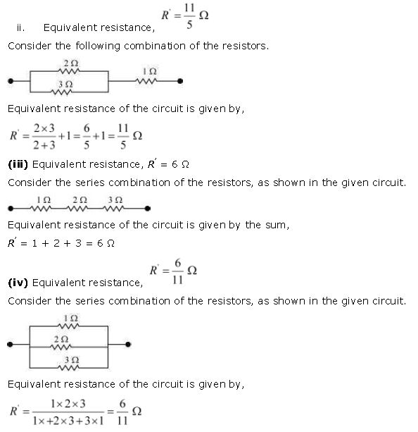
(b) Given the resistances of 1 Ω, 2 Ω, 3 Ω, how will be combine them to get an equivalent resistance of (i) (11/3) Ω (ii) (11/5) Ω, (iii) 6 Ω, (iv) (6/11) Ω?
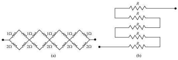
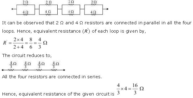
(c) Determine the equivalent resistance of networks shown in Fig. 3.31.
Answer : (a) Total number of resistors = n
Resistance of each resistor = R
(i) When n resistors are connected in series, effective resistance R1 is the maximum, given by the product nR.
Hence, maximum resistance of the combination, R1 = nR
(ii) When n resistors are connected in parallel, the effective resistance (R2) is the minimum, given by the ratio R/n.
Hence, minimum resistance of the combination, R2 = R/n
(iii) The ratio of the maximum to the minimum resistance is,
(c) (a) It can be observed from the given circuit that in the first small loop, two resistors of resistance 1 Ω each are connected in series.
Hence, their equivalent resistance = (1+1) = 2 Ω
It can also be observed that two resistors of resistance 2 Ω each are connected in series.
Hence, their equivalent resistance = (2 + 2) = 4 Ω
Therefore, the circuit can be redrawn as
(b) It can be observed from the given circuit that five resistors of resistance R each are connected in series.
Hence, equivalent resistance of the circuit = R + R + R + R + R
= 5 R
2
Question. Determine the current drawn from a 12 V supply with internal resistance 0.5 Ω by the infinite network shown in Fig. 3.32. Each resistor has 1 Ω resistance.

Answer : The resistance of each resistor connected in the given circuit, R = 1 Ω
Equivalent resistance of the given circuit = R’
The network is infinite. Hence, equivalent resistance is given by the relation,
R’ = 2 + (R’/R’ + 1)
or R’2 -2R’ -2 = 0
On solving R’ = (2+√4+8)/2
(Negative value of R’ cannot be accepted)
R’ = 1 + √3 Ω
R’ = 1 + 1.73 = 2.73 Ω
Internal resistance of the circuit, r = 0.5 Ω
Hence, total resistance of the given circuit = 2.73 + 0.5 = 3.23 Ω
Supply voltage, V = 12 V
According to Ω ’s Law, current drawn from the source is given by the ratio, = 12/3.23 = 3.72 A
Question. Figure 3.33 shows a potentiometer with a cell of 2.0 V and internal resistance 0.40 Ω maintaining a potential drop across the resistor wire AB. A standard cell which maintains a constant emf of 1.02 V (for very moderate currents up to a few mA) gives a balance point at 67.3 cm length of the wire. To ensure very low currents drawn from the standard cell, a very high resistance of 600 kΩ is put in series with it, which is shorted close to the balance point. The standard cell is then replaced by a cell of unknown emf ε and the balance point found similarly, turns out to be at 82.3 cm length of the wire.
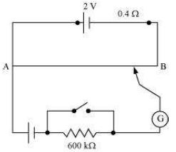
(a) What is the value ε ?
(b) What purpose does the high resistance of 600 kΩ have?
(c) Is the balance point affected by this high resistance?
(d) Is the balance point affected by the internal resistance of the driver cell?
(e) Would the method work in the above situation if the driver cell of the potentiometer had an emf of 1.0 V instead of 2.0 V?
(f ) Would the circuit work well for determining an extremely small emf, say of the order of a few mV (such as the typical emf of a thermo-couple)? If not, how will you modify the circuit?
Answer : a) Constant emf of the given standard cell, E1 = 1.02 V
Balance point on the wire, l1 = 67.3 cm
A cell of unknown emf, ε, replaced the standard cell. Therefore, new balance point on the wire,
l = 82.3 cm
The relation connecting emf and balance point is,
E1/l1 = E/l
E = l × E1/l1
E = 82.3 cm × 1.02 V/67.3 cm
E = 1.247 Volt.
The value of unknown emf is 1.247 V.
(b) Explanation:
The purpose of using the high resistance of 600 kΩ is to reduce the current through the galvanometer when the movable contact is far from the balance point.
(c) The balance point is not affected by the presence of high resistance.
(d) The point is not affected by the internal resistance of the driver cell.
(e) The method would not work if the driver cell of the potentiometer has an emf of 1.0 V instead of 2.0 V. This is because if the emf of the driver cell of the potentiometer is less than the emf of the other cell, then we cannot obtain balance point on the wire.
(f) The circuit would not work well for determining an extremely small emf. As the circuit would be unstable, the balance point would be close to end A. Hence, there would be a high percentage of error. The given circuit can be modified if a series resistance is connected with the wire AB. The potential drop across AB is slightly greater than the emf measured. The percentage error would be small.
Question. Figure 3.34 shows a potentiometer circuit for comparison of two resistances. The balance point with a standard resistor R = 10.0 Ω is found to be 58.3 cm, while that with the unknown resistance X is 68.5 cm. Determine the value of X. What might you do if you failed to find a balance point with the given cell of emf ε?
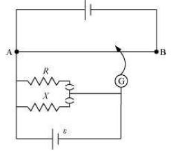
Answer : Resistance of the standard resistor, R = 10.0 Ω
Balance point for this resistance, l1 = 58.3 cm
Current in the potentiometer wire = i
Hence, potential drop across R, E1 = iR
Resistance of the unknown resistor = X
Balance point for this resistor, l2 = 68.5 cm
Hence, potential drop across X, E2 = iX
The relation connecting emf and balance point is,
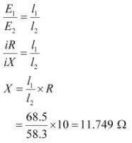
Therefore, the value of the unknown resistance, X, is 11.75 Ω. If we fail to find a balance point with the given cell of emf, ε, then the potential drop across R and X must be reduced by putting a resistance in series with it. Only if the potential drop across R or X is smaller than the potential drop across the potentiometer wire AB, a balance point is obtained.
Question. Figure 3.35 shows a 2.0 V potentiometer used for the determination of internal resistance of a 1.5 V cell. The balance point of the cell in open circuit is 76.3 cm. When a resistor of 9.5 Ω is used in the external circuit of the cell, the balance point shifts to 64.8 cm length of the potentiometer wire. Determine the internal resistance of the cell.
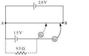
Answer : Internal resistance of the cell = r
Balance point of the cell in open circuit, l1 = 76.3 cm
An external resistance (R) is connected to the circuit with R = 9.5 Ω
New balance point of the circuit, l2 = 64.8 cm
Current flowing through the circuit = I
The relation connecting resistance and emf is,
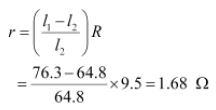
Therefore, the internal resistance of the cell is 1.68.Ω
Free study material for Physics
NCERT Solutions Class 12 Physics Chapter 3 Current Electricity
Students can now access the NCERT Solutions for Chapter 3 Current Electricity prepared by teachers on our website. These solutions cover all questions in exercise in your Class 12 Physics textbook. Each answer is updated based on the current academic session as per the latest NCERT syllabus.
Detailed Explanations for Chapter 3 Current Electricity
Our expert teachers have provided step-by-step explanations for all the difficult questions in the Class 12 Physics chapter. Along with the final answers, we have also explained the concept behind it to help you build stronger understanding of each topic. This will be really helpful for Class 12 students who want to understand both theoretical and practical questions. By studying these NCERT Questions and Answers your basic concepts will improve a lot.
Benefits of using Physics Class 12 Solved Papers
Using our Physics solutions regularly students will be able to improve their logical thinking and problem-solving speed. These Class 12 solutions are a guide for self-study and homework assistance. Along with the chapter-wise solutions, you should also refer to our Revision Notes and Sample Papers for Chapter 3 Current Electricity to get a complete preparation experience.
FAQs
The complete and updated is available for free on StudiesToday.com. These solutions for Class 12 Physics are as per latest NCERT curriculum.
Yes, our experts have revised the as per 2026 exam pattern. All textbook exercises have been solved and have added explanation about how the Physics concepts are applied in case-study and assertion-reasoning questions.
Toppers recommend using NCERT language because NCERT marking schemes are strictly based on textbook definitions. Our will help students to get full marks in the theory paper.
Yes, we provide bilingual support for Class 12 Physics. You can access in both English and Hindi medium.
Yes, you can download the entire in printable PDF format for offline study on any device.