

Class 12 Physics Study Guide: CBSE Class 12 Physics Past Year Important Questions
Review targeted academic resources with the CBSE Class 12 Physics Past Year Important Questions. Built according to official CBSE standards for the 2026-27 term, these downloadable Class 12 Physics study materials support effective daily practice and deeper conceptual understanding for All Chapters.
Download All Chapters Study Material PDF
Access the complete useful resource PDF for Class 12 Physics below. Regular practice with these targeted academic notes builds familiarity with complex topics and helps secure higher marks in final school evaluations.
CBSE Class 12 Physics Past Year Important Questions. Please refer to the examination notes which you can use for preparing and revising for exams. These notes will help you to revise the concepts quickly and get good marks.
CBSE CLASS 12 PHYSICS
PAST YEAR IMPORTANT QUESTIONS
ALL INDIA 2011, 2012 AND 2013 PAPERS
CBSE EXAMINATION PAPERS - ALL INDIA 2011
Time allowed: 3 hours. Maximum marks: 70
General Instructions:
(a) All questions are compulsory.
(b) There are 30 questions in total. Questions 1 to 8 carry one mark each, questions 9 to 18 carry two marks each, questions 19 to 27 carry three marks each and questions 28 to 30 carry five marks each.
(c) There is no overall choice. However, an internal choice has been provided in one question of two marks, one question of three marks and all three questions of five marks each. You have to attempt only one of the given choices in such questions.
(d) Use of calculators is not permitted.
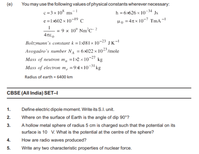
(e) You may use the following values of physical constants wherever necessary:
c = 3 × 10⁸ m s⁻¹; h = 6.626 × 10⁻³⁴ J s; e = 1.602 × 10⁻¹⁹ C; μ₀ = 4π × 10⁻⁷ T m A⁻¹; \( \frac{1}{4\pi\varepsilon_0} \) = 9 × 10⁹ N m² C⁻²
Boltzmann's constant k = 1.381 × 10⁻²³ J K⁻¹; Avogadro's number NA = 6.022 × 10²³ /mole; Mass of neutron mn = 1.2 × 10⁻²⁷ kg; Mass of electron me = 9.1 × 10⁻³¹ kg; Radius of earth = 6400 km
CBSE (All India) SET-I
1. Define electric dipole moment. Write its S.I. unit. [1 Mark]
Answer:
1. Electric dipole moment is the product of the magnitude of either charge and the distance between the two charges of the dipole: p = q × 2a.
2. It is a vector directed from the negative charge to the positive charge.
3. Its S.I. unit is coulomb metre (C m).
Teacher's Note:
a) Do not forget to state that it is a vector, pointing from -q to +q.
2. Where on the surface of Earth is the angle of dip 90°? [1 Mark]
Answer: At the magnetic poles of the Earth, where the magnetic field is vertical.
Teacher's Note:
a) Dip is 0° at the magnetic equator and 90° at the poles.
3. A hollow metal sphere of radius 5 cm is charged such that the potential on its surface is 10 V. What is the potential at the centre of the sphere? [1 Mark]
Answer:
1. Inside a charged hollow conductor the electric field is zero.
2. No work is done in moving a charge inside it, so the potential is constant throughout the interior and equals the surface value.
3. Hence the potential at the centre is 10 V.
Teacher's Note:
a) Zero field means constant potential, not zero potential.
4. How are radio waves produced? [1 Mark]
Answer: Radio waves are produced by the accelerated (rapidly oscillating) charges in a conducting wire or antenna connected to an oscillating LC circuit.
Teacher's Note:
a) Every electromagnetic wave originates from accelerated charges.
5. Write any two characteristic properties of nuclear force. [1 Mark]
Answer:
1. Nuclear force is a strong attractive force and is of very short range (a few femtometres).
2. It is independent of the electric charge: the p-p, n-n and p-n forces are nearly equal.
Teacher's Note:
a) Compare it with gravitational and electric forces to remember the key properties: stronger, short range, charge independent.
6. Two bar magnets are quickly moved towards a metallic loop connected across a capacitor 'C' as shown in the figure. Predict the polarity of the capacitor. [1 Mark]
[Figure: Two bar magnets lie on a common horizontal axis, one on each side of a thin vertical circular loop. The left magnet is labelled S (left end) and N (right end) with an arrow above it pointing towards the loop. The right magnet is labelled S (left end) and N (right end) with an arrow above it pointing towards the loop. A capacitor C is connected in the loop near its upper right side.]
Answer:
1. The N-pole of the left magnet and the S-pole of the right magnet both face the loop, so the magnetic flux through the loop, directed from left to right, increases.
2. By Lenz's law the induced current produces a magnetic field from right to left, opposing the increase of flux.
3. Hence the current is anticlockwise when seen from the left magnet and clockwise when seen from the right magnet.
4. The capacitor is charged by this induced emf: the plate connected to the end of the loop at which the current arrives becomes positive. In the figure the lower plate is positive and the upper plate is negative.
Teacher's Note:
a) Both poles help to increase the flux in the same direction, so their effects add and do not cancel.
7. What happens to the width of depletion layer of a p-n junction when it is (I) forward biased, (ii) reverse biased? [1 Mark]
Answer:
1. (i) Forward biased: the width of the depletion layer decreases.
2. (ii) Reverse biased: the width of the depletion layer increases.
Teacher's Note:
a) In forward bias the applied field opposes the barrier field, so the barrier is lowered.
8. Define the term 'stopping potential' in relation to photoelectric effect. [1 Mark]
Answer: The minimum negative (retarding) potential applied to the collector plate with respect to the emitter at which the photoelectric current becomes zero is called the stopping potential. It satisfies eV₀ = Kmax.
Teacher's Note:
a) Stopping potential depends on the frequency of the light and the metal, not on the intensity.
9. A thin straight infinitely long conducting wire having charge density λ is enclosed by a cylindrical surface of radius r and length l, its axis coinciding with the length of the wire. Find the expression for the electric flux through the surface of the cylinder. [2 Marks]
Answer:
1. The charge enclosed by the cylinder is q = λl.
2. By Gauss's law, the flux through the closed cylindrical surface is Φ = \( \frac{q}{\varepsilon_0} \).
3. Hence Φ = \( \frac{\lambda l}{\varepsilon_0} \).
Teacher's Note:
a) Gauss's law uses only the charge enclosed, so the radius r does not appear in the flux.
b) Check that the units of λ (C m⁻¹) times l (m) give a charge.
10. Plot a graph showing the variation of coulomb force (F) versus \( \frac{1}{r^{2}} \) where r is the distance between the two charges of each pair of charges: (1 µC, 2 µC) and (2 µC - 3 µC). Interpret the graphs obtained. [2 Marks]
Answer:
1. Coulomb force F = \( \frac{q_1 q_2}{4\pi\varepsilon_0} \) × \( \frac{1}{r^{2}} \), so the graph of F against \( \frac{1}{r^{2}} \) is a straight line through the origin whose slope is \( \frac{q_1 q_2}{4\pi\varepsilon_0} \).
2. Pair 1 (1 µC, 2 µC): slope = 9 × 10⁹ × 2 × 10⁻¹² = 1.8 × 10⁻² N m². The charges are of the same sign, so the force is repulsive and the line lies above the axis.
3. Pair 2 (2 µC, -3 µC): magnitude of slope = 9 × 10⁹ × 6 × 10⁻¹² = 5.4 × 10⁻² N m². The charges are of opposite sign, so the force is attractive and the line lies below the axis.
4. The slope for pair 2 is 3 times that for pair 1, so its line is steeper.
5. Interpretation: the force is directly proportional to \( \frac{1}{r^{2}} \) (inverse square law), and the slope of each line equals the product of the charges divided by 4πε₀.
[Figure: diagram to be added: two straight lines through the origin on a graph of F (vertical) against 1/r² (horizontal); the line for (1 µC, 2 µC) rises above the axis with smaller slope, and the line for (2 µC, -3 µC) falls below the axis with a slope three times as large in magnitude]
Teacher's Note:
a) Plot the attractive force on the negative side to show its direction.
b) The slope depends only on the product q₁q₂, so it fixes the strength of the interaction.
11. Write the expression for Lorentz magnetic force on a particle of charge 'q' moving with velocity v⃗ in a magnetic field B⃗. Show that no work is done by this force on the charged particle. [2 Marks]
Answer:
1. The Lorentz magnetic force is F⃗ = q(v⃗ × B⃗).
2. The work done in a small displacement dr⃗ = v⃗ dt is dW = F⃗ · dr⃗ = q(v⃗ × B⃗) · v⃗ dt.
3. Since v⃗ × B⃗ is perpendicular to v⃗, the scalar product (v⃗ × B⃗) · v⃗ = 0.
4. Hence dW = 0, so no work is done by the magnetic force and the kinetic energy of the particle stays constant.
Teacher's Note:
a) The magnetic force is always perpendicular to velocity, so it changes only the direction of motion.
b) A particle entering a uniform field perpendicularly moves in a circle with constant speed.
OR
A steady current (I₁) flows through a long straight wire. Another wire carrying steady current (I₂) in the same direction is kept close and parallel to the first wire. Show with the help of a diagram how the magnetic field due to the current I₁ exerts a magnetic force on the second wire. Write the expression for this force.
Answer:
1. The first wire produces a magnetic field at the second wire at distance d: B₁ = \( \frac{\mu_0 I_1}{2\pi d} \), directed perpendicular to the plane containing the two wires (the circular field lines of wire 1).
2. The force on a length l of the second wire is F₂ = I₂ l B₁, with direction given by l⃗ × B⃗₁.
3. For currents in the same direction this force on wire 2 points towards wire 1, so the wires attract each other.
4. The force per unit length is \( \frac{F}{l} \) = \( \frac{\mu_0 I_1 I_2}{2\pi d} \).
[Figure: diagram to be added: two long parallel wires carrying currents I₁ and I₂ in the same direction at separation d, with the magnetic field B₁ of wire 1 at wire 2 and the force F on wire 2 directed towards wire 1]
Teacher's Note:
a) Parallel currents attract and antiparallel currents repel.
b) This formula defines the ampere when I₁ = I₂ = 1 A and d = 1 m, giving 2 × 10⁻⁷ N m⁻¹.
12. What are eddy currents? Write any two applications of eddy currents. [2 Marks]
Answer:
1. Eddy currents are the closed loops of induced current set up in a bulk piece of conductor when the magnetic flux linked with it changes.
2. Application 1: induction furnace, used to melt metals.
3. Application 2: electromagnetic damping, as in the dead-beat galvanometer and magnetic braking of trains.
Teacher's Note:
a) Eddy currents oppose the change that produces them, as Lenz's law demands, and they heat the conductor.
b) Name the application and give the working idea in a few words, for example a furnace melting metal by eddy current heating.
13. What is sky wave communication? Why is this mode of propagation restricted to the frequencies only up to few MHz? [2 Marks]
Answer:
1. In sky wave communication, radio waves of frequency about 3 MHz to 30 MHz are radiated upward and reflected back to the Earth by the ionosphere, which allows communication over long distances.
2. Waves of higher frequency are not reflected by the ionosphere because the frequency exceeds the critical frequency (about 9 √Nmax, where Nmax is the maximum electron density), so they pass through it and are lost in space.
3. Hence this mode is limited to frequencies of only a few MHz.
Teacher's Note:
a) The ionosphere reflects only waves below its critical frequency.
b) Sky wave means reflection from the ionosphere; space wave means line of sight.
14. In the given circuit, assuming point A to be at zero potential, use Kirchhoff's rules to determine the potential at point B. [2 Marks]
[Figure: Rectangular circuit. Top branch from left to right: left corner, point D, a 2 V cell, then the top right corner B. Arrows on the top branch: 1 A pointing left on the segment left of D, and 2 A pointing towards D on the segment between the 2 V cell and D. Left side: resistor R from the top left corner down to point A. Middle: a 2 Ω resistor from D down to point C. Right side: resistor R₁ from B down to the bottom right corner. Bottom branch from left to right: point A, a 1 V cell, point C, then an arrow marked 2 A pointing right towards the bottom right corner.]
Answer:
1. At junction D the current entering is 2 A and 1 A goes along the left branch, so the current in the 2 Ω resistor is 2 - 1 = 1 A, directed from D to C.
2. Take VA = 0. The current flows through the 1 V cell from its negative to its positive terminal, so VC = VA + 1 = 1 V.
3. The current is from D to C in the 2 Ω resistor, so VD - VC = 1 × 2 = 2 V and VD = 3 V.
4. The 2 V cell carries current from B to D through its negative to positive terminal, so VD - VB = 2 V.
5. Hence VB = 3 - 2 = 1 V.
Teacher's Note:
a) Add the cell emf when the current goes from the negative to the positive terminal, and subtract it in the opposite direction.
b) Choose a path that avoids the unknown resistances R and R₁.
15. A parallel plate capacitor is being charged by a time varying current. Explain briefly how Ampere's circuital law is generalized to incorporate the effect due to the displacement current. [2 Marks]
Answer:
1. While the capacitor charges, the conduction current I flows in the wires but no conduction current flows in the gap between the plates, so Ampere's law ∮B⃗ · dl⃗ = μ₀I gives different results for two surfaces bounded by the same loop.
2. Maxwell added the displacement current Id = ε₀ \( \frac{d\Phi_E}{dt} \), due to the changing electric flux between the plates, which equals the conduction current I.
3. The generalized law is ∮B⃗ · dl⃗ = μ₀(I + Id) = μ₀I + μ₀ε₀ \( \frac{d\Phi_E}{dt} \), which makes the total current continuous.
Teacher's Note:
a) Displacement current is not a flow of charge; it comes from a changing electric field.
b) Mention continuity of total current to earn full credit.
16. Net capacitance of three identical capacitors in series is 1 µF. What will be their net capacitance if connected in parallel?
Find the ratio of energy stored in the two configurations if they are both connected to the same source. [2 Marks]
Answer:
1. Let each capacitor have capacitance C. In series Cs = \( \frac{C}{3} \) = 1 µF, so C = 3 µF.
2. In parallel Cp = 3C = 9 µF.
3. Energy U = \( \frac{1}{2} \) CV² with the same V, so Us : Up = Cs : Cp = 1 : 9.
Teacher's Note:
a) With the same potential difference, stored energy is directly proportional to capacitance.
b) Do not interchange the series and parallel formulas for capacitors.
17. Using the curve for the binding energy per nucleon as a function of mass number A, state clearly how the release in energy in the processes of nuclear fission and nuclear fusion can be explained. [2 Marks]
Answer:
1. The binding energy per nucleon rises steeply for light nuclei, is maximum (about 8.75 MeV) near A = 56, and falls slowly for heavy nuclei (about 7.6 MeV for A near 240).
2. Fission: a heavy nucleus splits into medium-mass nuclei that have a larger binding energy per nucleon, so the extra binding energy is released.
3. Fusion: light nuclei join to form a heavier nucleus with a larger binding energy per nucleon, and the difference is released as energy.
[Figure: diagram to be added: curve of binding energy per nucleon against mass number A, rising steeply to a peak near A = 56 and then falling slowly]
Teacher's Note:
a) Energy is released whenever nucleons move to a more tightly bound state, that is, towards the peak of the curve.
b) Mark the peak near A = 56 on the curve to show both sides of it.
18. In the meter bridge experiment, balance point was observed at J with AJ = l. [2 Marks]
[Figure: Meter bridge. A straight wire AB is connected between the two ends A (left) and B (right) of a rectangular circuit. Resistance R is in the left gap on the top side and resistance X is in the right gap on the top side. A galvanometer G is connected from the junction of R and X down to the jockey point J on the wire AB. A battery is connected between A and B below the wire. An arrow marked I points from A towards J.]
(i) The values of R and X were doubled and then interchanged. What would be the new position of balance point?
Answer:
1. At the first balance, \( \frac{R}{X} \) = \( \frac{l}{100 - l} \).
2. After doubling and interchanging, the resistances are R' = 2X and X' = 2R, so \( \frac{R'}{X'} \) = \( \frac{X}{R} \) = \( \frac{100 - l}{l} \).
3. If the new balance length is l', then \( \frac{l'}{100 - l'} \) = \( \frac{100 - l}{l} \), which gives l' = (100 - l) cm from A.
Teacher's Note:
a) Doubling both resistances does not change their ratio; interchanging inverts it.
b) Check: the new balance length l' = 100 - l satisfies the same ratio condition.
(ii) If the galvanometer and battery are interchanged at the balance position, how will the balance point get affected?
Answer: The balance point is not affected, because the balance condition \( \frac{R}{X} \) = \( \frac{l}{100 - l} \) of a Wheatstone bridge is the same when the battery and the galvanometer are interchanged.
Teacher's Note:
a) The balance condition is symmetric in the two diagonals of the bridge.
b) Only the sensitivity of the detection may change, not the position of the null point.
19. A convex lens made up of glass of refractive index 1.5 is dipped, in turn, in (i) a medium of refractive index 1.65, (ii) a medium of refractive index 1.33. [3 Marks]
(a) Will it behave as a converging or a diverging lens in the two cases?
Answer:
1. (i) In the medium of refractive index 1.65 the lens material (1.5) is optically rarer than the medium, so the lens behaves as a diverging lens.
2. (ii) In the medium of refractive index 1.33 the lens material is denser than the medium, so it behaves as a converging lens.
Teacher's Note:
a) The nature of a lens depends on the ratio of the refractive indices of the lens and the surrounding medium.
b) A convex shape converges light only when the lens is denser than its surroundings.
(b) How will its focal length change in the two media?
Answer:
1. By the lens maker's formula, \( \frac{1}{f} \) = (\( \frac{n_g}{n_m} \) - 1)(\( \frac{1}{R_1} \) - \( \frac{1}{R_2} \)), where f₀ is the focal length in air.
2. (i) In the medium 1.65: \( \frac{n_g}{n_m} \) - 1 = -0.091 against 0.5 in air, so the focal length becomes about -5.5 f₀ (negative, a diverging lens of much greater focal length).
3. (ii) In the medium 1.33: \( \frac{n_g}{n_m} \) - 1 = 0.128 against 0.5 in air, so the focal length becomes about 3.9 f₀, which is longer than in air.
Teacher's Note:
a) Focal length increases in both media; in the first one it also changes sign.
b) Work out the bracket (n of lens divided by n of medium, minus 1) for each medium.
20. Draw a plot showing the variation of photoelectric current with collector plate potential for two different frequencies, v₁ >v₂ , of incident radiation having the same intensity. In which case will the stopping potential be higher? Justify your answer. [3 Marks]
Answer:
1. The plot has two curves of photoelectric current against collector plate potential. Both curves have the same saturation current (same intensity), but they cut the negative potential axis at different stopping potentials, V₀₁ for v₁ and V₀₂ for v₂.
2. The stopping potential is higher for the radiation of frequency v₁.
3. Justification: eV₀ = hv - φ₀, so V₀ increases with the frequency. Since v₁ > v₂, V₀₁ > V₀₂.
[Figure: diagram to be added: photoelectric current (vertical) against collector plate potential (horizontal); two curves rise to the same saturation current; the curve for v₁ meets the potential axis at a larger negative value V₀₁ than the curve for v₂]
Teacher's Note:
a) The stopping potential depends on frequency only; intensity affects only the saturation current.
b) Mark both stopping potentials on the negative side of the axis.
c) The saturation currents of the two curves are equal because the intensity is the same.
21. Write briefly any two factors which demonstrate the need for modulating a signal. Draw a suitable diagram to show amplitude modulation using a sinusoidal signal as the modulating signal. [3 Marks]
Answer:
1. Factor 1: Size of the antenna. An antenna needs a length of about \( \frac{\lambda}{4} \), and for low-frequency audio signals this length is impractically large; modulation shifts the signal to a high frequency carrier so a short antenna can be used.
2. Factor 2: Effective power radiated. The power radiated by an antenna is proportional to \( \frac{1}{\lambda^{2}} \), so low-frequency signals radiate very little power; high-frequency modulated waves radiate effectively. Modulation also avoids the mixing of signals from different transmitters.
3. In amplitude modulation the amplitude of a high-frequency carrier wave is varied in proportion to the instantaneous value of the sinusoidal modulating signal, while the carrier frequency stays the same. The envelope of the modulated wave has the shape of the modulating signal.
[Figure: diagram to be added: three waveforms one below the other: the sinusoidal modulating signal, the high-frequency carrier wave, and the amplitude modulated wave whose envelope follows the modulating signal]
Teacher's Note:
a) Always connect the need for modulation to antenna length, power radiated and interference between signals.
b) Draw the carrier, the modulating signal and the AM wave one below the other, with the envelope clearly marked.
c) The carrier frequency must be much larger than the modulating frequency, so that the envelope is clear.
22. Use the mirror equation to show that [3 Marks]
(a) an object placed between f and 2f of a concave mirror produces a real image beyond 2f.
Answer:
1. Mirror equation: \( \frac{1}{v} \) + \( \frac{1}{u} \) = \( \frac{1}{f} \). For a concave mirror put u = -x and f = -F, with F less than x less than 2F.
2. Then \( \frac{1}{v} \) = \( \frac{1}{u} \) subtracted from \( \frac{1}{f} \) gives \( \frac{1}{v} \) = -\( \frac{1}{F} \) + \( \frac{1}{x} \) = -\( \frac{x - F}{Fx} \), which is negative, so the image is real.
3. Its distance is |v| = \( \frac{Fx}{x - F} \). The condition |v| greater than 2F becomes x greater than 2(x - F), that is x less than 2F, which is true.
4. Hence the image is real and lies beyond 2f.
Teacher's Note:
a) Use the sign convention carefully: for a concave mirror u and f are both negative.
b) Show the inequality step: x less than 2F is exactly the condition for v to be greater than 2F.
(b) a convex mirror always produces a virtual image independent of the location of the object.
Answer:
1. For a convex mirror f is positive and u is negative, u = -x.
2. \( \frac{1}{v} \) = \( \frac{1}{f} \) - \( \frac{1}{u} \) = \( \frac{1}{f} \) + \( \frac{1}{x} \), which is positive for every value of x.
3. So v is always positive, meaning the image is formed behind the mirror and is virtual wherever the object is placed.
Teacher's Note:
a) The sum of two positive terms can never be zero or negative, so a real image is impossible.
b) The image also always lies between the pole and the focus, so it is diminished.
(c) an object placed between the pole and focus of a concave mirror produces a virtual and enlarged image.
Answer:
1. For a concave mirror put u = -x and f = -F, with x less than F.
2. \( \frac{1}{v} \) = -\( \frac{1}{F} \) + \( \frac{1}{x} \) = \( \frac{F - x}{Fx} \), which is positive, so v is positive and the image is virtual, behind the mirror.
3. Magnification m = -\( \frac{v}{u} \) = \( \frac{v}{x} \) = \( \frac{F}{F - x} \), which is greater than 1 and positive.
4. Hence the image is virtual, erect and enlarged.
Teacher's Note:
a) Magnification greater than 1 means enlarged; its positive sign means erect.
b) This is why a concave mirror is used as a shaving or make-up mirror.
23. Draw a labelled diagram of a full wave rectifier circuit. State its working principle. Show the input-output waveforms. [3 Marks]
Answer:
1. Circuit: the input a.c. is applied across the primary of a centre-tapped transformer. The two ends of the secondary are connected to the p-sides of two junction diodes D₁ and D₂; the n-sides of both diodes are joined together and connected through the load resistance RL to the centre tap of the secondary. The output is taken across RL.
2. Principle: a p-n junction diode conducts only when it is forward biased. During one half cycle D₁ is forward biased and conducts while D₂ is reverse biased; during the other half cycle D₂ conducts while D₁ is off.
3. In both half cycles the current through RL flows in the same direction, so the output is a unidirectional pulsating d.c. with frequency twice that of the input.
4. Waveforms: the input is a continuous sine wave; the output consists of positive half-sine pulses for both half cycles of the input.
[Figure: diagram to be added: full wave rectifier circuit with centre-tapped transformer, diodes D₁ and D₂, load RL, and the input sine wave above the output wave made of continuous positive half cycles]
Teacher's Note:
a) State clearly that the output frequency is double the input frequency.
b) A capacitor filter across the load smooths the pulsating output.
c) The centre tap is the common return point for both diodes; without it the circuit does not work as full-wave.
24. (a) Using de Broglie's hypothesis, explain with the help of a suitable diagram, Bohr's second postulate of quantization of energy levels in a hydrogen atom. [3 Marks]
Answer:
1. According to de Broglie, the electron revolving in a circular orbit of radius r behaves as a wave of wavelength λ = \( \frac{h}{mv} \).
2. For the electron wave to be stable, the circumference must hold a whole number of wavelengths, forming a standing wave: 2πr = nλ, with n = 1, 2, 3, ...
3. Substituting λ: 2πr = \( \frac{nh}{mv} \), which gives mvr = \( \frac{nh}{2\pi} \).
4. This is Bohr's second postulate: the angular momentum of the electron in a stationary orbit is an integral multiple of \( \frac{h}{2\pi} \).
[Figure: diagram to be added: a circular electron orbit with a standing wave of whole number of wavelengths fitted around the circumference]
Teacher's Note:
a) Link the standing wave condition to the whole number n.
b) Orbits that do not satisfy 2πr = nλ cancel out by destructive interference.
(b) The ground state energy of hydrogen atom is -13.6 eV. What are the kinetic and potential energies of the electron in this state?
Answer:
1. Total energy E = -13.6 eV.
2. For an electron in a circular orbit, kinetic energy K = -E = +13.6 eV.
3. Potential energy U = 2E = -27.2 eV.
Teacher's Note:
a) Total energy is half the potential energy and the negative of the kinetic energy.
b) The negative total energy shows that the electron is bound to the nucleus.
25. You are given a circuit below. Write its truth table. Hence, identify the logic operation carried out by this circuit. Draw the logic symbol of the gate it corresponds to. [3 Marks]
[Figure: Logic circuit. Input A goes to a NOT gate whose output is labelled X. Input B goes to a second NOT gate whose output is labelled Y. X and Y are the two inputs of a NOR gate (an OR gate with a bubble at its output) whose output is labelled Z.]
Answer:
1. The two NOT gates give X = NOT A and Y = NOT B. The final gate is a NOR gate, so Z = NOT (X + Y) = NOT (NOT A + NOT B).
2. Using De Morgan's theorem, Z = A · B.
3. Truth table:
A = 0, B = 0: X = 1, Y = 1, Z = 0
A = 0, B = 1: X = 1, Y = 0, Z = 0
A = 1, B = 0: X = 0, Y = 1, Z = 0
A = 1, B = 1: X = 0, Y = 0, Z = 1
4. The circuit performs the AND operation. The AND gate symbol is a D-shaped gate with two inputs A and B and one output Z, without a bubble.
[Figure: diagram to be added: logic symbol of the AND gate with inputs A and B and output Z]
Teacher's Note:
a) Z is 1 only when both inputs are 1, which is the AND operation.
b) NOR followed by inverted inputs is another way to build an AND gate.
c) Write the intermediate columns X and Y in the table so that every step is visible.
OR
(a) State Huygen's principle. Using this principle explain how a diffraction pattern is obtained on a screen due to a narrow slit on which a narrow beam coming from a monochromatic source of light is incident normally.
Answer:
1. Huygens' principle: every point on a wavefront acts as a source of secondary wavelets, and the new wavefront at a later time is the forward envelope of these wavelets.
2. A plane wavefront reaches the slit, and every point of the slit acts as a source of secondary wavelets. These wavelets spread into the geometrical shadow and interfere on the screen.
3. At the centre of the screen all the wavelets arrive in phase, which gives the central maximum. At an angle θ the path difference between the extreme wavelets is a sin θ. When it equals nλ (n = 1, 2, 3, ...), the slit divides into pairs of points whose wavelets cancel, giving minima.
4. Between the minima the intensity rises to weak secondary maxima, so a central bright band with alternate dark and weak bright bands is obtained.
[Figure: diagram to be added: plane wavefront incident on a narrow slit of width a, secondary wavelets spreading to the screen, and the resulting intensity curve with a broad central maximum]
Teacher's Note:
a) Write the condition a sin θ = nλ for minima.
b) Do not confuse diffraction minima with the interference maxima of Young's experiment.
(b) Show that the angular width of the first diffraction fringe is half of that of the central fringe.
Answer:
1. The first minimum on either side of the centre occurs at sin θ = \( \frac{\lambda}{a} \), so θ₁ = \( \frac{\lambda}{a} \) for small angles.
2. Angular width of the central fringe = 2θ₁ = \( \frac{2\lambda}{a} \).
3. The first secondary maximum lies between the first minimum (θ₁ = \( \frac{\lambda}{a} \)) and the second minimum (θ₂ = \( \frac{2\lambda}{a} \)), so its angular width = θ₂ - θ₁ = \( \frac{\lambda}{a} \).
4. Hence the angular width of the first fringe is \( \frac{\lambda}{a} \), which is half of the angular width \( \frac{2\lambda}{a} \) of the central fringe.
Teacher's Note:
a) The central maximum is twice as wide as every other fringe.
b) Write the angular positions of the first and second minima to show the subtraction clearly.
(c) If a monochromatic source of light is replaced by white light, what change would you observe in the diffraction pattern?
Answer: The central maximum remains white, and the secondary maxima on both sides become coloured. Since the fringe width is proportional to wavelength, each coloured band is spread out, with violet nearest to the centre and red farthest from it.
Teacher's Note:
a) Red light diffracts more than violet light because its wavelength is longer.
b) The central maximum stays white because all colours are in phase at the centre.
CBSE (All India) SET-II
Questions uncommon to Set-I
1. A hollow metal sphere of radius 10 cm is charged such that the potential on its surface is 5V. What is the potential at the centre of the sphere?
Answer:
1. The electric field inside a charged hollow conductor is zero, so the potential is the same everywhere inside as on the surface.
2. Hence the potential at the centre is 5 V.
Teacher's Note:
a) Constant potential inside does not mean zero potential.
b) The radius given in the question is not needed.
2. How are X-rays produced?
Answer: X-rays are produced when high-speed electrons, accelerated through a high potential difference, strike a metal target of high atomic number and high melting point (as in a Coolidge tube); the sudden deceleration of the electrons produces X-rays.
Teacher's Note:
a) The rapid deceleration of electrons is the source of the continuous X-ray spectrum.
b) The characteristic lines arise from electron transitions in the target atoms.
3. Where on the surface of Earth is the angle of dip zero?
Answer: The angle of dip is zero at the magnetic equator, where the Earth's magnetic field is horizontal.
Teacher's Note:
a) Compare: dip is 90° at the magnetic poles.
b) Needles that are free to rotate in a vertical plane lie horizontal at the equator.
4. Net capacitance of three identical capacitors in series is 2 mF. What will be their net capacitance if connected in parallel?
Find the ratio of energy stored in the two configurations if they are both connected to the same source.
Answer:
1. For three identical capacitors of capacitance C in series, Cs = \( \frac{C}{3} \) = 2 mF, so C = 6 mF.
2. In parallel, Cp = 3C = 18 mF.
3. With the same source voltage, U = \( \frac{1}{2} \) CV², so Us : Up = Cs : Cp = 2 : 18 = 1 : 9.
Teacher's Note:
a) Stored energy at fixed voltage is proportional to the capacitance.
b) Keep the units (mF) as given in the question.
5. State the principle of working of a transformer. Can a transformer be used to step up or step down ad.c. voltage? Justify your answer.
Answer:
1. A transformer works on the principle of mutual induction: a changing current in the primary coil changes the magnetic flux linked with the secondary coil and induces an emf in it.
2. No, a transformer cannot be used to step up or step down a d.c. voltage.
3. A d.c. current is steady, so it produces a constant magnetic flux in the core. There is no change of flux in the secondary, so no emf is induced in it.
Teacher's Note:
a) A transformer needs a changing (alternating) current.
b) Only at the instant of switching a d.c. source on or off is a momentary emf induced.
6. In the given circuit, assuming point A to be at zero potential, use Kirchhoff's rules to determine the potential at point B.
[Figure: Rectangular circuit. Top branch from left to right: left top corner, point D, a 4 V cell, then point B at the top right corner. Arrows on the top branch: 1 A pointing left to the left of D, and 3 A pointing towards D between the 4 V cell and D. Left side: resistor R from the top left corner down to point A. Middle: a 2 Ω resistor from D down to point C. Right side: resistor R₁ from B down to the bottom right corner. Bottom branch from left to right: point A, a 2 V cell, point C, then an arrow marked 3 A pointing right towards the bottom right corner.]
Answer:
1. At junction D the current entering is 3 A and 1 A goes along the left branch, so the current in the 2 Ω resistor is 3 - 1 = 2 A, directed from D to C.
2. Take VA = 0. The current passes through the 2 V cell from its negative to its positive terminal, so VC = 0 + 2 = 2 V.
3. The potential drop in the 2 Ω resistor is 2 × 2 = 4 V, so VD = VC + 4 = 6 V.
4. The 4 V cell carries current from B to D (negative to positive terminal), so VD - VB = 4 V.
5. Hence VB = 6 - 4 = 2 V.
Teacher's Note:
a) Find the current in the middle branch first by applying the junction rule at D.
b) Use only the cells and the 2 Ω resistor in the path, as R and R₁ are unknown.
7. What is ground wave communication? On what factors does the maximum range of propagation in this mode depend?
Answer:
1. In ground wave (surface wave) communication, the radio waves travel along the surface of the Earth, following its curvature, from the transmitting antenna to the receiving antenna. It is used for low frequencies, up to about 1500 kHz.
2. The maximum range depends on the power of the transmitter, the frequency of the wave (attenuation rises with frequency), and the nature of the ground over which the wave travels.
Teacher's Note:
a) Higher frequencies are absorbed strongly by the ground, so ground waves are used only for low frequencies.
b) Name all three factors: power, frequency and ground nature.
8. You are given a circuit below. Write its truth table. Hence, identify the logic operation carried out by this circuit. Draw the logic symbol of the gate it corresponds to.
[Figure: Logic circuit. Input A goes to both inputs of a NAND gate whose output is labelled X. Input B goes to both inputs of a second NAND gate whose output is labelled Y. X and Y are the two inputs of a third NAND gate whose output is labelled Z.]
Answer:
1. Each of the first two gates is a NAND gate with its two inputs joined, so it acts as a NOT gate: X = NOT A and Y = NOT B.
2. The last gate is a NAND gate, so Z = NOT (X · Y) = NOT (NOT A · NOT B). By De Morgan's theorem, Z = A + B.
3. Truth table:
A = 0, B = 0: X = 1, Y = 1, Z = 0
A = 0, B = 1: X = 1, Y = 0, Z = 1
A = 1, B = 0: X = 0, Y = 1, Z = 1
A = 1, B = 1: X = 0, Y = 0, Z = 1
4. The circuit performs the OR operation. The OR gate symbol has two inputs A and B and one output Z, with a curved input side and a pointed output side and no bubble.
[Figure: diagram to be added: logic symbol of the OR gate with inputs A and B and output Z]
Teacher's Note:
a) Z is 0 only when both inputs are 0, which is the OR operation.
b) A NAND gate with joined inputs is a NOT gate.
9. A compound microscope uses an objective lens of focal length 4 cm and eyepiece lens of focal length 10 cm. An object is placed at 6 cm from the objective lens. Calculate the magnifying power of the compund microscope. Also calculate the length of the microscope.
Answer:
1. Objective: uo = -6 cm, fo = 4 cm. From \( \frac{1}{v_o} \) = \( \frac{1}{f_o} \) + \( \frac{1}{u_o} \) = \( \frac{1}{4} \) - \( \frac{1}{6} \) = \( \frac{1}{12} \), vo = 12 cm.
2. Magnification of the objective mo = \( \frac{v_o}{u_o} \) = -2.
3. Taking the final image at the least distance of distinct vision D = 25 cm, the eyepiece magnification is me = 1 + \( \frac{D}{f_e} \) = 1 + \( \frac{25}{10} \) = 3.5.
4. Magnifying power m = mo × me = -2 × 3.5 = -7, that is, a magnification of 7.
5. For the eyepiece, ve = -25 cm, fe = 10 cm: \( \frac{1}{u_e} \) = \( \frac{1}{v_e} \) - \( \frac{1}{f_e} \) = -\( \frac{1}{25} \) - \( \frac{1}{10} \) = -\( \frac{7}{50} \), so ue = -7.14 cm.
6. Length of the microscope L = vo + |ue| = 12 + 7.14 = 19.14 cm.
Teacher's Note:
a) The question does not state where the final image forms; the usual assumption is the least distance of distinct vision, 25 cm.
b) Length is the distance between the two lenses, not the sum of the focal lengths.
c) The negative sign of the magnification shows that the final image is inverted.
OR
A giant refracting telescope at an observatory has an objective lens of focal length 15m. If an eyepiece lens of focal length 1.0 cm is used, find the angular magnification of the telescope. If this telescope is used to view the moon, what is the diameter of the image of the moon formed by the objective lines ? The diameter of the moon in 3.42 x 10⁶ m and the radius of the lunar orbit is 3.8 x 10⁸ m.
Answer:
1. Angular magnification in normal adjustment m = \( \frac{f_o}{f_e} \) = \( \frac{15 \text{ m}}{0.01 \text{ m}} \) = 1500.
2. Angle subtended by the Moon at the objective: α = \( \frac{3.42 \times 10^{6}}{3.8 \times 10^{8}} \) = 9 × 10⁻³ rad.
3. The image formed by the objective lies in its focal plane, so its diameter = α × fo = 9 × 10⁻³ × 15 = 0.135 m.
4. Hence the diameter of the image of the Moon is 13.5 cm.
Teacher's Note:
a) Convert both focal lengths to the same unit before dividing.
b) The objective forms a real image of the Moon at its focus; the eyepiece then magnifies it.
10. Two heating elements of resistance R₁ and R₂ when operated at a constant supply of voltage, V, consume power P₁ and P₂ respectively. Deduce the expressions for the power of their combination when they are, in turn, connected in (i) series and (ii) parallel across the same voltage supply.
Answer:
1. From P = \( \frac{V^{2}}{R} \): R₁ = \( \frac{V^{2}}{P_1} \) and R₂ = \( \frac{V^{2}}{P_2} \).
2. (i) Series: Rs = R₁ + R₂, so \( \frac{V^{2}}{P_s} \) = \( \frac{V^{2}}{P_1} \) + \( \frac{V^{2}}{P_2} \). Hence \( \frac{1}{P_s} \) = \( \frac{1}{P_1} \) + \( \frac{1}{P_2} \), that is, Ps = \( \frac{P_1 P_2}{P_1 + P_2} \).
3. (ii) Parallel: each element has voltage V across it, so Pp = \( \frac{V^{2}}{R_1} \) + \( \frac{V^{2}}{R_2} \) = P₁ + P₂.
Teacher's Note:
a) Powers add in parallel but their reciprocals add in series.
b) Check: for equal elements the series power is one quarter of the parallel power.
11. (a) State the principle of the working of a moving coil galvanometer giving its labelled diagram.
Answer:
1. A current-carrying coil placed in a uniform radial magnetic field experiences a torque, and the coil rotates until the restoring torque of the spring balances the magnetic torque.
2. Torque on the coil = NIAB. Restoring torque = kφ. At equilibrium NIAB = kφ, so the deflection φ = \( \frac{NAB}{k} \) I, which is proportional to the current I.
3. Diagram: a rectangular coil of N turns wound on a soft iron core, suspended between the concave pole pieces of a strong horse-shoe magnet by a fine phosphor-bronze strip, with a hair spring and a pointer moving over a scale.
[Figure: diagram to be added: moving coil galvanometer showing the coil, soft iron core, concave pole pieces N and S, suspension strip, spring and pointer with scale]
Teacher's Note:
a) The radial field keeps the torque the same at every angle, so the scale is linear.
b) The soft iron core increases the magnetic field strength and makes the field radial.
(b) "Increasing" the current sensitivity of a galvanometer may not necessarily increase its voltage sensitivity, "Justify this statement
Answer:
1. Current sensitivity Is = \( \frac{\varphi}{I} \) = \( \frac{NAB}{k} \), and voltage sensitivity Vs = \( \frac{\varphi}{V} \) = \( \frac{NAB}{kR} \) = \( \frac{I_s}{R} \), where R is the resistance of the galvanometer.
2. If the current sensitivity is increased by increasing the number of turns N, the resistance R of the coil also increases in the same proportion, so the ratio \( \frac{NAB}{kR} \) remains unchanged.
3. Hence an increase in the current sensitivity does not necessarily increase the voltage sensitivity.
Teacher's Note:
a) Voltage sensitivity is current sensitivity divided by resistance.
b) Writing Vs = Is / R makes the argument short and clear.
OR
(a) Outline the necessary law, obtain the expression for the magnetic field due to a long solenoid at a point inside the solenoid on its axis.
Answer:
1. The law used is Ampere's circuital law: ∮B⃗ · dl⃗ = μ₀ × (current enclosed).
2. Take a rectangular Amperian loop abcd with side ab = l inside the solenoid, parallel to the axis, and the other sides outside or perpendicular to the axis. The field outside the long solenoid is negligible and the field is perpendicular to the sides bc and da.
3. The line integral is B l. If n is the number of turns per unit length, the current enclosed is n l I.
4. So B l = μ₀ n l I, which gives B = μ₀nI.
[Figure: diagram to be added: long solenoid with a rectangular Amperian loop abcd, side ab inside parallel to the axis]
Teacher's Note:
a) The field inside a long solenoid is uniform and does not depend on the position along the axis.
b) This expression also holds well away from the ends.
(b) How is the magnetic field inside a given solenoid strong ?
Answer: The magnetic field inside a given solenoid is made stronger by increasing the current I through it, and by placing a soft iron core inside it, which increases the field by a factor equal to its relative permeability.
Teacher's Note:
a) The question is read as how the field inside a given solenoid can be made strong.
b) B = μ₀nI shows that it also grows with the number of turns per unit length.
12. State the working of a.c. generator with the help of a labelled diagram. The coil of an a.c. generator having N turns, each of area A, is rotated with a constant angular velocity ω. Deduce the expression for the alternating e.m.f. generated in the coil.
What is the source of energy generation in this device ?
Answer:
1. Principle: an a.c. generator works on electromagnetic induction. When a coil is rotated in a uniform magnetic field, the magnetic flux linked with it changes and an emf is induced.
2. Working: the armature coil rotates between the poles of a magnet; its ends are joined to two slip rings, which touch carbon brushes connected to the external circuit.
3. At time t, the angle between the coil's area vector and the field B is θ = ωt. Flux φ = NBA cos ωt.
4. Induced emf e = -\( \frac{d\varphi}{dt} \) = NBAω sin ωt, so e = e₀ sin ωt with peak emf e₀ = NBAω.
5. The source of energy is the mechanical energy used to rotate the coil, for example from a turbine driven by water or steam.
[Figure: diagram to be added: a.c. generator showing the rotating coil between N and S poles, slip rings, brushes and the external circuit]
Teacher's Note:
a) The emf is zero when the coil is perpendicular to the field and maximum when it is parallel to it.
b) The generator converts mechanical energy into electrical energy.
c) Always give the peak emf expression e₀ = NBAω.
OR
(a) Show that in an a.c. circuit containing a pure inductor, the voltage is ahead of current by π/2 in phase.
Answer:
1. Let the applied voltage be v = v₀ sin ωt across a pure inductor L.
2. The induced emf in the inductor is -L \( \frac{di}{dt} \). Kirchhoff's loop rule gives v - L \( \frac{di}{dt} \) = 0, so \( \frac{di}{dt} \) = \( \frac{v_0}{L} \) sin ωt.
3. Integrating, i = -\( \frac{v_0}{\omega L} \) cos ωt = i₀ sin(ωt - \( \frac{\pi}{2} \)), where i₀ = \( \frac{v_0}{\omega L} \).
4. Thus the current lags the voltage by \( \frac{\pi}{2} \), that is, the voltage is ahead of the current by \( \frac{\pi}{2} \).
Teacher's Note:
a) Remember the trick: in an inductor the voltage leads the current (L: V before I).
b) ωL is the inductive reactance XL.
(b) A horizontal straight wire of length L extending from east to west is falling with speed v at right angles to the horizontal component of Earth's magnetic field B.
(i) Write the expression for the instantaneous value of interference.
Answer: The induced emf in the wire is e = BvL, where v is the instantaneous speed of the wire (v = gt for free fall).
Teacher's Note:
a) The word "interference" in the printed question is a misprint for the induced emf, which is what is asked.
b) The emf grows with time as the speed of the falling wire increases.
(ii) What is the direction of the e.m.f. ?
Answer:
1. The velocity is vertically downward and the field is towards the north.
2. By the right-hand rule, the force on positive charges is v⃗ × B⃗, which points from west to east.
3. Hence the emf acts from west to east along the wire.
Teacher's Note:
a) Use Fleming's right-hand rule: thumb for motion, forefinger for field, middle finger for current.
b) Check with Lenz's law: the current would oppose the downward motion.
(iii) Which end of the wire is at the higher potential ?
Answer: Positive charges are pushed towards the east end, so the east end of the wire is at the higher potential.
Teacher's Note:
a) The end towards which the emf drives positive charge becomes positive.
b) Answer (ii) and (iii) must be consistent: the emf points towards the higher potential end.
13. State the importance of coherent sources in the phenomenon of interference. In Young's double slit experiment to produce interference patten, obtain the conditions for constructive and desructive interference. Hence, deduce the expression for the fringe width. How does the fringe width get affected, if entire experimental apparatus of Young is immersed in water ?
Answer:
1. Importance of coherent sources: two sources that keep a constant phase difference give a stable interference pattern with fixed positions of bright and dark fringes; with incoherent sources the pattern changes rapidly and the average intensity is uniform.
2. In Young's experiment the slits S₁ and S₂ are separated by d and the screen is at distance D. For a point P at distance y from the centre, the path difference is S₂P - S₁P = \( \frac{yd}{D} \).
3. Constructive interference (bright fringe): path difference = nλ, so yn = \( \frac{n\lambda D}{d} \), n = 0, ±1, ±2, ...
4. Destructive interference (dark fringe): path difference = (n + \( \frac{1}{2} \))λ, so yn = (n + \( \frac{1}{2} \)) \( \frac{\lambda D}{d} \).
5. Fringe width β = yn+1 - yn = \( \frac{\lambda D}{d} \).
6. In water the wavelength becomes λ' = \( \frac{\lambda}{\mu} \), so the new fringe width β' = \( \frac{\beta}{\mu} \) decreases (to \( \frac{3}{4} \) of its value, as μ = \( \frac{4}{3} \)).
[Figure: diagram to be added: Young's double slit arrangement with slits S₁ and S₂ separated by d, screen at distance D and a point P at distance y from the centre]
Teacher's Note:
a) The fringe width is the same for all bright and dark fringes.
b) Frequency does not change in a medium; only the wavelength and speed change.
c) Mention that D and d are unchanged when the whole apparatus is immersed.
Questions uncommon to Set - I and II
1. A hollow metal sphere of radius 6 cm is charged such that the potential on its surface is 12 V. What is the potential at the centre of the sphere?
Answer:
1. The field inside a charged hollow conductor is zero, so the potential inside is constant and equal to the surface potential.
2. Hence the potential at the centre is 12 V.
Teacher's Note:
a) Potential inside is equal to the surface potential, not zero.
b) The radius is a distractor and is not used.
2. How are microwaves produced?
Answer: Microwaves are produced by special vacuum tubes such as the klystron, the magnetron and the Gunn diode, in which electrons oscillate in resonant cavities at very high frequency.
Teacher's Note:
a) Ordinary LC circuits cannot reach microwave frequencies.
b) Name at least one device; the klystron and the magnetron are the usual ones.
3. Where on the surface of Earth is the vertical component of Earth's magnetic field zero?
Answer: At the magnetic equator, where the angle of dip is zero and the Earth's field is entirely horizontal.
Teacher's Note:
a) Vertical component = B sin δ, which is zero when the dip δ = 0.
b) The same place has the horizontal component equal to the total field.
4. Mention various energy losses in a transformer.
Answer:
1. Copper loss: heat produced (I²R) in the resistance of the primary and secondary windings.
2. Iron loss: eddy current loss in the core and hysteresis loss due to repeated magnetisation of the core.
3. Flux leakage: not all the flux of the primary links the secondary; also some energy is lost as sound (humming).
Teacher's Note:
a) Laminating the core reduces eddy currents; a soft iron core reduces hysteresis loss.
b) Thick copper wire lowers the copper loss.
5. In the given circuit, assuming point A to be at zero potential, use Kirchhoff's rules to determine the potential at point B.
[Figure: Rectangular circuit. Top branch: left top corner, point D, a 6 V cell, then the top right corner. Arrows on the top branch: 1 A pointing left to the left of D, and 4 A pointing towards D between the 6 V cell and D. Left side: resistor R from the top left corner down to point A. Middle: a 2 Ω resistor from D down to point C. Right side: resistor R₁ from the top right corner (point B) down to the bottom right corner. Bottom branch from left to right: point A, a 3 V cell, point C, then an arrow marked 4 A pointing right.]
Answer:
1. At junction D the current entering is 4 A and 1 A goes along the left branch, so the current in the 2 Ω resistor is 4 - 1 = 3 A, directed from D to C.
2. Take VA = 0. The current passes through the 3 V cell from its negative to its positive terminal, so VC = 3 V.
3. The drop in the 2 Ω resistor is 3 × 2 = 6 V, so VD = 3 + 6 = 9 V.
4. The 6 V cell carries current from B to D (negative to positive terminal), so VD - VB = 6 V.
5. Hence VB = 9 - 6 = 3 V.
Teacher's Note:
a) Use the junction rule at D first, and then walk from A to B through the cells and the 2 Ω resistor only.
b) A cell adds its emf when the path crosses it from the negative to the positive plate.
6. A converging lens has a focal length of 20 cm in air. It is made of a material of refractive index 1,6. It is immersed in a liquid of refractive index 1.3. Calculate its new focal length.
Answer:
1. Lens maker's formula in air: \( \frac{1}{f_a} \) = (n - 1)(\( \frac{1}{R_1} \) - \( \frac{1}{R_2} \)) with n = 1.6 (the printed 1,6 is 1.6).
2. In the liquid: \( \frac{1}{f_l} \) = (\( \frac{n}{n_l} \) - 1)(\( \frac{1}{R_1} \) - \( \frac{1}{R_2} \)).
3. Dividing, \( \frac{f_l}{f_a} \) = \( \frac{n - 1}{\frac{n}{n_l} - 1} \) = \( \frac{0.6}{\frac{0.3}{1.3}} \) = 2.6.
4. Hence fl = 2.6 × 20 = 52 cm.
Teacher's Note:
a) The focal length increases when the lens is placed in a denser medium.
b) Take care to write n divided by n of the liquid, not the other way round.
7. You are given a circuit below. Write its truth table. Hence, identify the logic operation carried out by this circuit. Draw the logic symbol of the gate it corresponds to.
[Figure: Logic circuit. Input A goes to both inputs of a NOR gate whose output is labelled X. Input B goes to both inputs of a second NOR gate whose output is labelled Y. X and Y are the two inputs of a third NOR gate whose output is labelled Z.]
Answer:
1. Each of the first two gates is a NOR gate with its inputs joined, so it acts as a NOT gate: X = NOT A and Y = NOT B.
2. The last gate is a NOR gate, so Z = NOT (X + Y) = NOT (NOT A + NOT B). By De Morgan's theorem, Z = A · B.
3. Truth table:
A = 0, B = 0: X = 1, Y = 1, Z = 0
A = 0, B = 1: X = 1, Y = 0, Z = 0
A = 1, B = 0: X = 0, Y = 1, Z = 0
A = 1, B = 1: X = 0, Y = 0, Z = 1
4. The circuit performs the AND operation. The AND gate symbol is a D-shaped gate with inputs A and B and output Z, without a bubble.
[Figure: diagram to be added: logic symbol of the AND gate with inputs A and B and output Z]
Teacher's Note:
a) Z = 1 only when both inputs are 1, which is the AND operation.
b) A NOR gate with joined inputs is a NOT gate.
CBSE EXAMINATION PAPERS - ALL INDIA 2012
Time allowed: 3 hours. Maximum marks: 70
As given in CBSE Examination Papers Delhi-2011.
CBSE (All India) Set-I
1. Two wires of equal length, one of copper and the other of manganin have the same resistance. Which wire is thicker?
Answer:
1. R = \( \frac{\rho l}{A} \), so for equal R and l, the area of cross-section A is proportional to the resistivity ρ.
2. Manganin has a much higher resistivity than copper, so the manganin wire has the larger cross-section.
3. Hence the manganin wire is thicker.
Teacher's Note:
a) Equal length and equal resistance mean that area is proportional to resistivity.
b) Manganin is an alloy of high resistivity, which is why it is used for standard resistance coils.
2. What are the directions of electric and magnetic field vectors relative to each other and relative to the direction of propagation of electromagnetic waves?
Answer: The electric field vector and the magnetic field vector are perpendicular to each other, and both are perpendicular to the direction of propagation of the wave. The wave travels along the direction of E⃗ × B⃗.
Teacher's Note:
a) Electromagnetic waves are transverse in nature.
b) The three vectors E, B and the direction of travel form a right-handed set.
3. How does the angular separation between fringes in single-slit diffraction experiment change when the distance of separation between the slit and screen is doubled?
Answer: The angular separation between fringes, θ = \( \frac{\lambda}{a} \), does not depend on the distance of the screen, so it does not change (although the linear fringe width doubles).
Teacher's Note:
a) Angular width depends only on λ and the slit width a.
b) Linear width is \( \frac{\lambda D}{a} \) and would double.
4. A bar magnet is moved in the direction indicated by the arrow between two coils PQ and CD. Predict the directions of induced current in each coil
[Figure: A bar magnet with its left half dark (marked N) and its right half light (marked S) lies on a horizontal line between two coils. An arrow above the magnet points to the right. The coil on the left has its ends marked P and Q at the top and an ammeter A at the bottom; the coil on the right has its ends marked C and D at the top and an ammeter A at the bottom.]
Answer:
1. The magnet moves from the coil PQ towards the coil CD. The N-pole is towards PQ and the S-pole is towards CD.
2. Coil PQ: the magnet is moving away from it, so the flux of the N-pole through it decreases. By Lenz's law the induced current opposes this decrease, so the face of PQ towards the magnet becomes a S-pole to attract the magnet. The induced current is clockwise as seen from the magnet's side.
3. Coil CD: the S-pole of the magnet is approaching, so the flux through CD increases. By Lenz's law the induced current opposes this increase, so the face of CD towards the magnet becomes a S-pole to repel the magnet. The induced current is clockwise as seen from the magnet's side.
Teacher's Note:
a) Apply Lenz's law to each coil separately: the induced effect always opposes the motion.
b) Clockwise current seen from a face makes that face a S-pole.
5. For the same value of angle incidence, the angles of refraction in three media A, B and C are 15°, 25° and 35° respectively. In which medium would the velocity of light be minimum?
Answer:
1. Refractive index n = \( \frac{\sin i}{\sin r} \), so for the same i, the smaller the angle of refraction r, the larger the refractive index.
2. Medium A has the smallest angle of refraction (15°), so it has the highest refractive index.
3. Since v = \( \frac{c}{n} \), the velocity of light is minimum in medium A.
Teacher's Note:
a) A larger refractive index means a slower speed of light.
b) Snell's law sin i / sin r = n gives the comparison directly.
6. A proton and an electron have same kinetic energy. Which one has greater de-Broglie wavelengthand why?
Answer:
1. The de Broglie wavelength is λ = \( \frac{h}{\sqrt{2mK}} \).
2. For the same kinetic energy K, λ is inversely proportional to the square root of the mass.
3. The electron has the smaller mass, so the electron has the greater de Broglie wavelength.
Teacher's Note:
a) For equal momentum the wavelengths would be the same; here the equal quantity is the kinetic energy.
b) The result can also be seen from λ = h/p with p = √(2mK).
7. Mention the two characteristic properties of the material suitable for making core of a transformer.
Answer:
1. The material should have high permeability and low hysteresis loss (narrow hysteresis loop, as in soft iron).
2. It should also have high electrical resistivity so that eddy current losses are small.
Teacher's Note:
a) The core is also laminated to reduce eddy currents further.
b) Soft iron meets both requirements; steel does not, as it has high hysteresis loss.
8. A charge 'q' is placed at the centre of a cube of side l. What is the electric flux passing through each face of the cube?
Answer:
1. By Gauss's law, the total flux through the cube is \( \frac{q}{\varepsilon_0} \).
2. The six faces are identical and the charge is at the centre, so the flux through each face is \( \frac{q}{6\varepsilon_0} \).
Teacher's Note:
a) Symmetry divides the total flux equally among the six faces.
b) The side l is not needed.
9. A test charge 'q' is moved without acceleration from A to C along the path from A to B and then from B to C in electric field E as shown in the figure. (i) Calculate the potential difference between A and C. (ii) At which point (of the two) is the electric potential more and why?
[Figure: Uniform electric field E shown by four horizontal parallel lines with arrows pointing to the right. Point B is at (2, 3), point C is at (2, 0) and point A is at (6, 0). A straight arrow runs from A to B (marked at B) and a vertical arrow runs from B down to C. A dashed horizontal line joins C and A.]
Answer:
1. (i) The field is uniform and along the +x direction. The potential difference depends only on the displacement along the field. A is at x = 6 and C is at x = 2, so the displacement along E from C to A is 6 - 2 = 4 (coordinates taken in metres).
2. Hence VC - VA = E × 4, so the potential difference between A and C is 4E volts. The leg BC is perpendicular to E, so no potential change occurs along it.
3. (ii) The potential falls in the direction of the electric field. C is further against the direction of E than A is, so the potential is more at C.
Teacher's Note:
a) Only the component of displacement along the field changes the potential.
b) Moving along a line perpendicular to E is an equipotential path.
10. An electric dipole is held in a uniform electric field.
(i) Show that the net force acting on it is zero.
Answer:
1. The dipole has charges +q and -q separated by 2a, placed in a uniform field E.
2. The force on +q is qE along the field and the force on -q is qE opposite to the field.
3. The net force = qE - qE = 0, so a dipole in a uniform field experiences no net force (only a torque).
Teacher's Note:
a) The two forces are equal and opposite but do not act along the same line, so they form a couple.
b) Net force is zero but the torque pE sin θ is not zero unless the dipole is aligned with the field.
(ii) The dipole is aligned parallel to the field. Find the work done in rotating it through the angle of 180°
Answer:
1. The work done in rotating a dipole from angle θ₁ to θ₂ is W = pE(cos θ₁ - cos θ₂).
2. Here θ₁ = 0° and θ₂ = 180°, so W = pE(1 - (-1)) = 2pE.
3. Hence the work done is 2pE.
Teacher's Note:
a) This work is stored as the difference in potential energy between the stable and unstable positions.
b) Check with U = -pE cos θ: U changes from -pE to +pE, a change of 2pE.
11. State the underlying principle of a transformer. How is the large scale transmission of electric energy over long distances done with the use of transformers?
Answer:
1. Principle: a transformer works on mutual induction. A changing current in the primary coil produces a changing flux in the core, which induces an emf in the secondary coil.
2. At the power station the voltage is stepped up by a step-up transformer to a very high value. For the same power P = VI, the current in the transmission lines becomes small, so the power loss I²R in the lines is reduced.
3. Near the consumers, step-down transformers at the sub-stations reduce the voltage to a safe value (220 V) for use.
Teacher's Note:
a) High voltage and low current make the long-distance transmission efficient.
b) Transformers work only with a.c.
12. A capacitor of capacitance of 'C' is being charged by connecting it across a dc source along with an ammeter. Will the ammeter show a momentary deflection during the process of charging? If so, how would you explain this momentary deflection and the resulting continuity of current in the circuit? Write the expression for the current inside the capacitor.
Answer:
1. Yes, the ammeter shows a momentary deflection while the capacitor charges, because the charging current flows in the wires until the capacitor is fully charged.
2. Between the plates there is no flow of charge, but the electric field between the plates keeps changing as the charge on the plates increases. This changing electric flux gives rise to a displacement current inside the capacitor.
3. The displacement current is equal to the conduction current in the wires, so the total current is continuous throughout the circuit.
4. The current inside the capacitor is Id = ε₀ \( \frac{d\Phi_E}{dt} \).
Teacher's Note:
a) Displacement current exists only while the electric field is changing.
b) When the capacitor is fully charged the current and the deflection become zero.
13. An object AB is kept in front of a concave mirror as shown in the figure.
(i) Complete the ray diagram showing the image formation of the object.
(ii) How will the position and intensity of the image be affected if the lower half of the mirror's reflecting surface is painted black?
[Figure: A concave mirror on the right with its principal axis horizontal. Object AB stands vertically on the axis at the left with A at the top and B on the axis. Along the axis, from left to right, are B, then the centre of curvature C, then the focus F, then the mirror.]
Answer:
1. (i) Ray diagram: a ray from A parallel to the principal axis is reflected through the focus F. A ray from A through the centre of curvature C is reflected back along the same path. The two reflected rays meet at A'. The image A'B' is formed between F and C. It is real, inverted and diminished.
2. (ii) If the lower half of the mirror is painted black, the image is still formed at the same position and has the same size, because the rays from the upper half of the mirror still meet at the same point. But only half the light is reflected, so the intensity of the image becomes half (the image is dimmer).
[Figure: diagram to be added: ray diagram showing the image A'B' between F and C, real, inverted and diminished]
Teacher's Note:
a) Each part of a mirror forms the complete image; blocking part reduces only the brightness.
b) Use two principal rays to locate the image.
14. Draw a labelled ray diagram of a reflecting telescope. Mention its two advantages over the refracting telescope.
Answer:
1. Diagram (Cassegrain type): parallel rays from a distant object fall on a concave parabolic primary mirror, which reflects them towards its focus. A small convex secondary mirror, placed before the focus, reflects the rays through a hole in the primary mirror to the eyepiece, where the final image is seen.
2. Advantage 1: there is no chromatic aberration because mirrors are used, and a parabolic mirror removes spherical aberration.
3. Advantage 2: a large mirror can be made lighter and can be supported from the back, so a larger aperture is possible, which gives a brighter and more resolved image.
[Figure: diagram to be added: Cassegrain reflecting telescope with parallel rays, primary concave mirror with a central hole, secondary convex mirror and eyepiece]
Teacher's Note:
a) Label the primary mirror, secondary mirror, eyepiece and the focal point.
b) Larger aperture gives more light-gathering power and better resolving power.
15. Describe briefly with the help of a circuit diagram, how the flow of current carries in a p-n-p transistor is regulated with emitter-base junction forward biased and base-collector junction reverse biased.
Answer:
1. Circuit: the emitter is connected to the positive terminal of the battery VEB and the base to its negative terminal, so the emitter-base junction is forward biased. The collector is connected through a load resistor to the negative terminal of a second battery VCB, so the base-collector junction is reverse biased.
2. The heavily doped emitter sends a large number of holes into the base, forming the emitter current IE.
3. The base is thin and lightly doped, so only a few holes (about 2 to 5 percent) combine with electrons there, forming the small base current IB. The rest of the holes cross into the collector under the reverse bias field and form the collector current IC.
4. Hence IE = IB + IC, and a small change in the emitter-base voltage controls the large collector current.
[Figure: diagram to be added: p-n-p transistor with emitter-base battery (forward bias) and collector-base battery (reverse bias) with load resistor]
Teacher's Note:
a) The thin, lightly doped base is the key to transistor action.
b) In a p-n-p transistor the holes are the main carriers inside the transistor.
16. In the given block diagram of a receiver, identify the boxes labelled as X and Y and write their functions.
[Figure: Block diagram of a receiver: Receiving antenna, then Amplifier, then box X, then Detector, then box Y, then Output.]
Answer:
1. X is the intermediate frequency (IF) stage. It converts the high carrier frequency of the received signal to a lower, fixed intermediate frequency, which is easier to amplify and detect.
2. Y is the amplifier (audio amplifier). It amplifies the signal recovered by the detector to a suitable power level for the output device.
Teacher's Note:
a) The detector separates the message signal from the carrier wave.
b) The IF stage keeps the receiver gain and selectivity constant at all station frequencies.
17. A light bulb is rated 100 W for 220 V ac supply of 50 Hz. Calculate
(i) the resistance of the bulb;
Answer:
1. P = \( \frac{V^{2}}{R} \), so R = \( \frac{V^{2}}{P} \) = \( \frac{220 \times 220}{100} \) = 484 Ω.
Teacher's Note:
a) The rated voltage is the rms value.
b) Use P = V²/R because the rated power and voltage are given.
(ii) the rms current through the bulb
Answer:
1. Irms = \( \frac{P}{V} \) = \( \frac{100}{220} \) = 0.45 A (approximately).
Teacher's Note:
a) Cross-check with I = \( \frac{V}{R} \) = \( \frac{220}{484} \) = 0.45 A.
b) The rms current is what an a.c. ammeter reads.
OR
An alternating voltage given by V = 140 sin 314 t is connected across a pure resistor of 50 Ω. Find
(i) the frequency of the source.
Answer:
1. Comparing V = V₀ sin ωt, ω = 314 rad s⁻¹.
2. f = \( \frac{\omega}{2\pi} \) = \( \frac{314}{2 \times 3.14} \) = 50 Hz.
Teacher's Note:
a) Always compare with the standard form first.
b) The 2π in the denominator comes from ω = 2πf.
(ii) the rms current through the resistor.
Answer:
1. Peak current I₀ = \( \frac{V_0}{R} \) = \( \frac{140}{50} \) = 2.8 A.
2. Irms = \( \frac{I_0}{\sqrt{2}} \) = \( \frac{2.8}{1.414} \) = 1.98 A, that is about 2 A.
Teacher's Note:
a) Divide the peak value by √2 to get the rms value.
b) The rms current also equals Vrms / R with Vrms = 140 / √2 = 99 V.
18. A circular coil of N turns and radius R carries a current I. It is unwound and rewound to make another coil of radius R/2, current I remaining the same. Calculate the ratio of the magnetic moments of the new coil and the original coil.
Answer:
1. The length of the wire stays the same: N × 2πR = N' × 2π \( \frac{R}{2} \), so N' = 2N.
2. Original magnetic moment m₁ = N I πR².
3. New magnetic moment m₂ = N' I π \( \left(\frac{R}{2}\right)^{2} \) = 2N I \( \frac{\pi R^{2}}{4} \) = \( \frac{NI\pi R^{2}}{2} \).
4. Hence m₂ : m₁ = 1 : 2.
Teacher's Note:
a) The number of turns doubles but the area becomes one-fourth.
b) The total length of wire is the quantity that remains constant.
19. Deduce the expression for the electrostatic energy stored in a capacitor of capacitance 'C' and having charge 'Q'.
How will the (i) energy stored and (ii) the electric field inside the capacitor be affected when it is completely filled with a dielectric material of dielectric constant 'K'?
Answer:
1. Let the charge on the plates be q at some instant, so the potential difference is V = \( \frac{q}{C} \). The work done in bringing a further charge dq is dW = V dq = \( \frac{q}{C} \) dq.
2. Total work done in charging from 0 to Q is W = \( \int_0^Q \frac{q}{C} dq \) = \( \frac{Q^{2}}{2C} \). This is stored as the energy: U = \( \frac{Q^{2}}{2C} \) = \( \frac{1}{2} \) CV² = \( \frac{1}{2} \) QV.
3. Taking the capacitor to be isolated (charge Q constant), on filling it with a dielectric the capacitance becomes C' = KC.
4. (i) The energy stored becomes U' = \( \frac{Q^{2}}{2KC} \) = \( \frac{U}{K} \), so it decreases by a factor K.
5. (ii) The electric field becomes E' = \( \frac{E}{K} \), so it decreases by a factor K.
Teacher's Note:
a) State clearly the assumption that the charge stays constant.
b) If the battery stays connected, V is constant, the energy becomes KU and the field stays E.
c) The same derivation works with C and V as variables.
20. Calculate the value of the resistance R in the circuit shown in the figure so that the current in the circuit is 0.2 A. What would be the potential difference between points B and E?
[Figure: Circuit. Top branch: an 8 V cell on the left with a 0.2 A arrow pointing right towards point B, then a 5 Ω resistor from B to the top right corner C. Left side: a 15 Ω resistor going down from the top left corner, then a 3 V cell, then the bottom left corner. Bottom branch: resistor R and a 0.2 A arrow pointing left, reaching point E. A 30 Ω resistor joins B to E vertically. A 10 Ω resistor runs diagonally from B to the bottom right corner D, which is joined to E by a wire. A 10 Ω resistor joins C to D on the right side.]
Answer:
1. The 8 V and 3 V cells oppose each other in the loop, so the net emf is 8 - 3 = 5 V.
2. Between B and E: the 5 Ω and 10 Ω resistors in the right arm are in series (15 Ω) and are in parallel with the 10 Ω diagonal resistor, giving \( \frac{15 \times 10}{15 + 10} \) = 6 Ω. This 6 Ω is in parallel with the 30 Ω resistor, so RBE = \( \frac{30 \times 6}{30 + 6} \) = 5 Ω.
3. Total resistance = \( \frac{5}{0.2} \) = 25 Ω = 15 + 5 + R, so R = 5 Ω.
4. Potential difference between B and E = 0.2 × 5 = 1 V.
Teacher's Note:
a) When cells oppose each other, subtract their emfs.
b) Reduce the resistor network in steps: series first, then parallel.
21. You are given three lenses L₁, L₂ and L₃ each of focal length 20 cm. An object is kept at 40 cm in front of L₁, as shown. The final real image is formed at the focus 'I' of L₃. Find the separations between L₁, L₂ and L₃.
[Figure: Three convex lenses L₁, L₂ and L₃ lie on a common horizontal axis from left to right at equal spacings in the drawing. An upright object arrow stands on the axis to the left of L₁, with the distance 40 cm marked between the object and L₁. A point I on the axis to the right of L₃ is marked, with the distance 20 cm marked between L₃ and I.]
Answer:
1. For L₁: u = -40 cm, f = +20 cm. From \( \frac{1}{v} \) = \( \frac{1}{f} \) + \( \frac{1}{u} \) = \( \frac{1}{20} \) - \( \frac{1}{40} \) = \( \frac{1}{40} \), so v = 40 cm. L₁ forms its image 40 cm to the right of L₁.
2. The final image is at the focus of L₃, so the rays falling on L₃ must be parallel to the axis. This means that L₂ must form its image at infinity, so the image formed by L₁ must lie at the focus of L₂, 20 cm to the left of L₂.
3. Hence the separation between L₁ and L₂ is 40 + 20 = 60 cm.
4. Since the beam leaving L₂ is parallel, L₃ focuses it at its focus whatever its position; so the separation between L₂ and L₃ can have any value.
Teacher's Note:
a) The final image at the focus of a lens means the rays entering it are parallel.
b) Parallel rays from L₂ come only from an object placed at the focus of L₂.
22. Define the terms (i) 'cut-off voltage' and (ii) 'threshold frequency' in relation to the phenomenon of photoelectric effect.
Using Einstein's photoelectric equation show how the cut-off voltage and threshold frequency for a given photosensitive material can be determined with the help of a suitable plot/graph.
Answer:
1. (i) Cut-off voltage (stopping potential) V₀ is the minimum negative potential of the collector with respect to the emitter at which the photoelectric current becomes zero.
2. (ii) Threshold frequency ν₀ is the minimum frequency of the incident radiation below which no photoelectric emission takes place, whatever the intensity.
3. Einstein's equation: hν = φ₀ + Kmax, with Kmax = eV₀. So V₀ = \( \frac{h}{e} \) ν - \( \frac{\phi_0}{e} \).
4. Plot the cut-off voltage V₀ against the frequency ν of the incident radiation. It is a straight line with slope \( \frac{h}{e} \).
5. The intercept of the line on the frequency axis (where V₀ = 0) gives the threshold frequency ν₀ = \( \frac{\phi_0}{h} \). The intercept on the voltage axis is -\( \frac{\phi_0}{e} \), and the cut-off voltage for any frequency is read from the line.
[Figure: diagram to be added: straight line graph of cut-off voltage V₀ (vertical) against frequency ν (horizontal), meeting the frequency axis at ν₀ and the voltage axis at a negative value]
Teacher's Note:
a) The slope of the graph gives h/e, a way of finding Planck's constant.
b) Intensity does not change the cut-off voltage.
23. A series LCR circuit is connected to an ac source. Using the phasor diagram, derive the expression for the impedance of the circuit. Plot a graph to show the variation of current with frequency of the source, explaining the nature of its variation.
Answer:
1. Let the source voltage be v = v₀ sin ωt and the current be i = i₀ sin(ωt + φ). The voltages across the elements are: VR = IR (in phase with I), VL = IXL (ahead of I by 90°), VC = IXC (behind I by 90°).
2. In the phasor diagram, VL and VC are opposite, so their resultant is (VL - VC) at right angles to VR. The source voltage is V = \( \sqrt{V_R^{2} + (V_L - V_C)^{2}} \).
3. Substituting: V = I \( \sqrt{R^{2} + (X_L - X_C)^{2}} \), so the impedance Z = \( \frac{V}{I} \) = \( \sqrt{R^{2} + \left(\omega L - \frac{1}{\omega C}\right)^{2}} \), and tan φ = \( \frac{X_C - X_L}{R} \).
4. Variation of current with frequency: at low frequency XC is large and the current is small; as the frequency increases the current rises, reaching its maximum I = \( \frac{V}{R} \) at the resonant frequency ω₀ = \( \frac{1}{\sqrt{LC}} \), where XL = XC and Z = R. Beyond ω₀, XL becomes large and the current falls again.
[Figure: diagram to be added: phasor diagram of VR, VL, VC and the resultant V, and the bell-shaped resonance curve of current against frequency with its peak at ω₀]
Teacher's Note:
a) At resonance the impedance is minimum and equal to R.
b) The curve is a symmetric bell-shaped resonance curve; a smaller R gives a sharper peak.
24. Mention three 'different modes of propagation used in communication system. Explain with the help of a diagram how long distance communication can be achieved by ionospheric reflection of radio waves.
Answer:
1. The three modes of propagation are ground (surface) wave propagation, sky wave propagation and space wave propagation.
2. In sky wave propagation, radio waves of frequency between about 3 MHz and 30 MHz are transmitted upward from the antenna towards the ionosphere.
3. The ionosphere contains layers of ionised gases (the F-layer at about 300 km is the most important). The waves are refracted and reflected back to the Earth by this layer.
4. The reflected waves reach the Earth at a place far from the transmitter, and by repeated reflections between the ionosphere and the ground, signals can be sent over very long distances around the Earth.
[Figure: diagram to be added: transmitting antenna, ionosphere layer, reflected sky wave path returning to the Earth at the receiving antenna, with a curved Earth surface]
Teacher's Note:
a) Waves with a frequency above the critical frequency of the ionosphere pass through it and are not reflected.
b) The other two modes also need to be named.
25. Draw a plot of potential energy of a pair of nucleons as a function of their separations. Mark the regions where the nuclear force is (i) attractive and (ii) repulsive. Write any two characteristic features of nuclear forces.
Answer:
1. The plot of potential energy U(r) against separation r: for large r the potential energy is near zero; as r decreases it falls to a minimum of about -8 MeV at r = r₀ ≈ 0.8 fm, and for r less than r₀ it rises steeply and becomes positive.
2. (i) For r greater than r₀ the potential energy increases with r, so the force F = -\( \frac{dU}{dr} \) is attractive. (ii) For r less than r₀ the potential energy decreases with r, so the force is repulsive.
3. Feature 1: nuclear forces are very strong, short-range forces (a few fm).
4. Feature 2: they are charge independent, so the n-n, p-p and n-p forces are nearly the same.
[Figure: diagram to be added: potential energy U(r) against r with a minimum near r₀ = 0.8 fm, the repulsive region marked for r less than r₀ and the attractive region marked for r greater than r₀]
Teacher's Note:
a) The minimum of the curve is the point of stable equilibrium at which the force is zero.
b) Label the axes, with r in fm and U in MeV, and mark r₀ on the axis.
26. In a Geiger-Marsden experiment, calculate the distance of closest approach to the nucleus of Z = 80, when an α-particle of 8 MeV energy impinges on it before it comes momentarily to rest and reverses its direction.
How will the distance of closest approach be affected when the kinetic energy of the α-particle is doubled?
Answer:
1. At the distance of closest approach r₀ the whole kinetic energy of the α-particle becomes electrostatic potential energy: K = \( \frac{1}{4\pi\varepsilon_0} \) \( \frac{(2e)(Ze)}{r_0} \).
2. r₀ = \( \frac{9 \times 10^{9} \times 2 \times 80 \times (1.6 \times 10^{-19})^{2}}{8 \times 10^{6} \times 1.6 \times 10^{-19}} \) = \( \frac{9 \times 10^{9} \times 160 \times 1.6 \times 10^{-19}}{8 \times 10^{6}} \).
3. r₀ = 2.88 × 10⁻¹⁴ m.
4. Since r₀ is inversely proportional to K, doubling the kinetic energy halves the distance of closest approach to 1.44 × 10⁻¹⁴ m.
Teacher's Note:
a) Energy in MeV must be converted to joules (1 eV = 1.6 × 10⁻¹⁹ J).
b) Check the order of magnitude: nuclear sizes are around 10⁻¹⁴ m.
OR
The ground state energy of hydrogen atom is - 13.6 eV. If an electron makes a transition from an energy level - 0.85 eV to -3.4 eV, calculate the wavelength of the spectral line emitted. To which series of hydrogen spectrum does this wavelength belong?
Answer:
1. Energy of the photon emitted = -0.85 - (-3.4) = 2.55 eV.
2. λ = \( \frac{hc}{E} \) = \( \frac{1240 \text{ eV nm}}{2.55 \text{ eV}} \) = 486 nm = 4.86 × 10⁻⁷ m.
3. The level -0.85 eV is n = 4 (E = -\( \frac{13.6}{16} \)) and the level -3.4 eV is n = 2 (E = -\( \frac{13.6}{4} \)).
4. The transition 4 → 2 belongs to the Balmer series.
Teacher's Note:
a) Identify the levels by E = -13.6 / n².
b) A final level n = 2 always means the Balmer series.
27. Define relaxation time of the free electrons drifting in a conductor. How is it related to the drift velocity of free electrons? Use this relation to deduce the expression for the electrical resistivity of the material.
Answer:
1. Relaxation time τ is the average time between two successive collisions of a free electron with the ions of the conductor.
2. Under a field E the electron has acceleration a = \( \frac{eE}{m} \), so the drift velocity is vd = aτ = \( \frac{eE\tau}{m} \).
3. The current density J = n e vd = \( \frac{n e^{2} \tau}{m} \) E, where n is the number density of free electrons.
4. Since J = σE, the conductivity is σ = \( \frac{ne^{2}\tau}{m} \).
5. The resistivity is ρ = \( \frac{1}{\sigma} \) = \( \frac{m}{ne^{2}\tau} \).
Teacher's Note:
a) Resistivity depends on the nature of the material (n and τ) and not on the shape of the conductor.
b) With rising temperature τ decreases, so the resistivity of a metal increases.
28. (a) In Young's double slit experiment, derive the condition for (i) constructive interference and (ii) destructive interference at a point on the screen.
Answer:
1. Let the slits S₁ and S₂ be separated by d and let the screen be at distance D. For a point P at distance y from the central point O, the path difference is Δ = S₂P - S₁P ≈ \( \frac{yd}{D} \).
2. (i) Constructive interference: Δ = nλ, so \( \frac{yd}{D} \) = nλ, and the bright fringes are at y = \( \frac{n\lambda D}{d} \), n = 0, 1, 2, ...
3. (ii) Destructive interference: Δ = (n + \( \frac{1}{2} \))λ, so the dark fringes are at y = (n + \( \frac{1}{2} \)) \( \frac{\lambda D}{d} \), n = 0, 1, 2, ...
[Figure: diagram to be added: Young's double slit set-up with slits S₁, S₂, separation d, screen at distance D and point P at distance y from O]
Teacher's Note:
a) Derivation needs the approximation d much smaller than D.
b) State both the path difference formula and the resulting positions of the bright and dark fringes.
(b) A beam of light consisting of two wavelengths, 800 nm and 600 nm is used to obtain the interference fringes in a Young's double slit experiment on a screen placed 1.4 m away. If the two slits are separated by 0.28 mm, calculate the least distance from the central bright maximum where the bright fringes of the two wavelengths coincide.
Answer:
1. The n₁th bright fringe of 800 nm coincides with the n₂th bright fringe of 600 nm when n₁ × 800 = n₂ × 600, so \( \frac{n_1}{n_2} \) = \( \frac{3}{4} \).
2. The least values are n₁ = 3 and n₂ = 4.
3. y = \( \frac{n_1 \lambda_1 D}{d} \) = \( \frac{3 \times 800 \times 10^{-9} \times 1.4}{0.28 \times 10^{-3}} \) = 1.2 × 10⁻² m.
4. Check with the other wavelength: \( \frac{4 \times 600 \times 10^{-9} \times 1.4}{0.28 \times 10^{-3}} \) = 1.2 × 10⁻² m.
5. Hence the least distance is 12 mm.
Teacher's Note:
a) Use the simplest whole-number ratio of the fringe orders.
b) Convert nanometres, millimetres and metres consistently.
OR
(a) How does an unpolarised light incident on a polaroid get polarised? Describe briefly, with the help of a necessary diagram, the polarisation of light by reflection from a transparent medium.
Answer:
1. A polaroid contains long chain molecules aligned in one direction. It absorbs the component of the electric field along the molecules and transmits only the component perpendicular to them, so the transmitted light is plane polarised.
2. Polarisation by reflection: when unpolarised light falls on a transparent surface at the particular angle of incidence iB (the Brewster angle), the reflected light is completely plane polarised, with its electric vector perpendicular to the plane of incidence.
3. At this angle the reflected and refracted rays are at 90° to each other, and tan iB = μ (Brewster's law).
[Figure: diagram to be added: unpolarised ray incident at the Brewster angle, the polarised reflected ray and the refracted ray at 90° to the reflected ray]
Teacher's Note:
a) Quote Brewster's law: tan iB = μ.
b) The reflected light is polarised perpendicular to the plane of incidence.
(b) Two polaroids 'A' and 'B' are kept in crossed position. How should a third polaroid 'C' be placed between them so that the intensity of polarised light transmitted by polaroid B reduces to 1/8th of the intensity of unpolarised light incident on A?
Answer:
1. Let I₀ be the intensity of the unpolarised light. After A the intensity is \( \frac{I_0}{2} \).
2. Let the pass-axis of C make an angle θ with that of A, and 90° - θ with that of B. By Malus's law, the intensity after C is \( \frac{I_0}{2} \) cos²θ, and after B it is \( \frac{I_0}{2} \) cos²θ cos²(90° - θ) = \( \frac{I_0}{2} \) cos²θ sin²θ = \( \frac{I_0}{8} \) sin²2θ.
3. Setting this equal to \( \frac{I_0}{8} \) gives sin²2θ = 1, so 2θ = 90° and θ = 45°.
4. Hence the pass-axis of C should be at 45° to the pass-axes of both A and B.
Teacher's Note:
a) The result is the maximum possible transmitted intensity through the crossed pair.
b) Without C the transmitted intensity would be zero, since A and B are crossed.
29. (a) Describe briefly, with the help of a diagram, the role of the two important processes involved in the formation of a p-n junction.
Answer:
1. Diffusion: electrons from the n-region (higher concentration) diffuse into the p-region, and holes from the p-region diffuse into the n-region. This diffusion current leaves behind immobile positive donor ions on the n-side and negative acceptor ions on the p-side.
2. Drift: the layer of these immobile ions, the depletion region, sets up an electric field directed from the n-side to the p-side. This field makes the minority carriers drift in the direction opposite to diffusion.
3. Equilibrium is reached when the drift current equals the diffusion current, giving a steady barrier potential across the junction.
[Figure: diagram to be added: p-n junction with diffusion and drift current directions and the depletion region]
Teacher's Note:
a) The depletion region has no free carriers.
b) Diffusion creates the depletion layer; drift opposes it.
(b) Name the device which is used as a voltage-regulator. Draw the necessary circuit diagram and explain its working.
Answer:
1. The Zener diode is used as a voltage regulator.
2. Circuit: the Zener diode is connected in reverse bias across the load resistor RL, and a series resistor Rs is connected between the unregulated d.c. input and the diode.
3. Working: the diode is operated in its breakdown region, where the voltage across it stays almost constant (Vz) even though the current through it changes a lot.
4. If the input voltage increases, the current through the Zener diode increases and the extra voltage drops across Rs, so the voltage across the load stays Vz. If the input voltage decreases, the Zener current decreases and the drop across Rs becomes smaller, so the output remains Vz.
[Figure: diagram to be added: Zener diode voltage regulator circuit with series resistor Rs, reverse biased Zener diode and load RL in parallel]
Teacher's Note:
a) The series resistor limits the current to protect the diode.
b) Name the Zener diode and state that it works in reverse bias.
OR
(a) Explain briefly the principle on which a transistor-amplifier works as an oscillator. Draw the necessary circuit diagram and explain its working.
Answer:
1. Principle: an oscillator is an amplifier with positive feedback. Part of the output energy is fed back to the input in phase with the input, so the oscillations are maintained without any external input signal.
2. Circuit: an n-p-n transistor in common-emitter connection has a tank circuit made of an inductance L and a capacitance C in the collector circuit. A feedback coil L' in the base circuit is inductively coupled to the coil L.
3. Working: when the supply is switched on, the collector current rises and charges C. The tank circuit then oscillates with the frequency ν = \( \frac{1}{2\pi\sqrt{LC}} \). The oscillating current in L induces a voltage in the feedback coil L', which is applied to the base in the right phase and amplified, supplying the energy lost in the tank circuit.
4. Thus steady oscillations of constant amplitude are obtained at the output.
[Figure: diagram to be added: transistor oscillator circuit with tank circuit L and C in the collector and feedback coil in the base]
Teacher's Note:
a) Positive feedback means the fed-back signal is in phase with the input.
b) The frequency is fixed by the LC tank circuit.
(b) Identify the equivalent gate for the following circuit and write its truth table.
[Figure: Logic circuit. Input A goes to a NOT gate whose output is labelled A'. Input B goes to a second NOT gate whose output is labelled B'. A' and B' are the two inputs of a NOR gate (an OR gate with a bubble at its output) whose output is labelled Y.]
Answer:
1. The two NOT gates give A' = NOT A and B' = NOT B. The last gate is a NOR gate, so Y = NOT (A' + B') = NOT (NOT A + NOT B) = A · B.
2. The equivalent gate is the AND gate.
3. Truth table:
A = 0, B = 0: Y = 0
A = 0, B = 1: Y = 0
A = 1, B = 0: Y = 0
A = 1, B = 1: Y = 1
Teacher's Note:
a) Y is 1 only when both inputs are 1.
b) Write the intermediate outputs A' and B' in the table when explaining.
30. (a) Write the expression for the force, F⃗ acting on a charged particle of charge 'q', moving with a velocity v⃗ in the presence of both electric field E⃗ and magnetic field B⃗. Obtain the condition under which the particle moves undeflected through the fields.
Answer:
1. The force on the particle is F⃗ = q(E⃗ + v⃗ × B⃗).
2. The particle moves undeflected when the net force on it is zero, so the electric force balances the magnetic force: qE⃗ + q(v⃗ × B⃗) = 0.
3. For E⃗, B⃗ and v⃗ mutually perpendicular, with the two forces opposite, the magnitudes give qE = qvB.
4. Hence the condition is v = \( \frac{E}{B} \).
[Figure: diagram to be added: charged particle moving along x with E along y and B along z, with the electric and magnetic forces opposite]
Teacher's Note:
a) This is the principle of the velocity selector; the charge and mass do not enter the condition.
b) For the forces to cancel, E⃗, B⃗ and v⃗ must be mutually perpendicular in the right sense.
(b) A rectangular loop of size l × b carrying a steady current I is placed in a uniform magnetic field B⃗. Prove that the torque τ⃗ acting on the loop is given by τ⃗ = m⃗ × B⃗, where m⃗ is the magnetic moment of the loop.
Answer:
1. Let the normal to the plane of the loop make an angle θ with B⃗, so the plane of the loop makes an angle (90° - θ) with the field. The sides of length b are perpendicular to the field, and the sides of length l make the angle (90° - θ) with it.
2. The forces on the two sides of length l are equal and opposite and act along the same line (axis of the loop), so they cancel and produce no torque.
3. The forces on the sides of length b each have magnitude F = IbB, are equal and opposite, and form a couple. The perpendicular distance between them is l sin θ.
4. Torque τ = F × l sin θ = I b B l sin θ = IAB sin θ, where A = lb.
5. With magnetic moment m = IA (direction along the normal to the loop), τ = mB sin θ, that is τ⃗ = m⃗ × B⃗.
[Figure: diagram to be added: rectangular loop of sides l and b in a uniform field B making an angle θ between its normal and B, with the forces on the sides]
Teacher's Note:
a) The forces on the sides parallel to the field direction cancel each other and do not produce a torque.
b) The torque is maximum when the plane of the loop is parallel to the field.
OR
(a) Explain, giving reasons, the basic difference in converting a galvanometer into (i) a voltmeter and (ii) an ammeter.
Answer:
1. (i) Voltmeter: a high resistance R = \( \frac{V}{I_g} \) - G is connected in series with the galvanometer. The resistance of the instrument becomes very large, so that it draws a negligible current from the circuit and is connected in parallel across the component whose potential difference is measured.
2. (ii) Ammeter: a low resistance (shunt) S = \( \frac{I_g G}{I - I_g} \) is connected in parallel with the galvanometer. The resistance of the instrument becomes very small, so that it does not change the current in the circuit and it is connected in series.
3. The basic difference is the series high resistance for the voltmeter and the parallel low resistance for the ammeter.
Teacher's Note:
a) Here Ig is the full-scale current and G the resistance of the galvanometer.
b) An ideal voltmeter has infinite resistance and an ideal ammeter has zero resistance.
(b) Two long straight parallel conductors carrying steady current I₁ and I₂ are separated by a distance 'd'. Explain briefly, with the help of a suitable diagram, how the magnetic field due to one conductor acts on the other. Hence deduce the expression for the force acting between the conductors. Mention the nature of this force.
Answer:
1. The conductor 1 produces at the position of conductor 2 (distance d) a magnetic field B₁ = \( \frac{\mu_0 I_1}{2\pi d} \), perpendicular to the plane of the two conductors.
2. The conductor 2, carrying current I₂, experiences a force F = I₂ L B₁ on a length L, perpendicular to both the wire and B₁.
3. The force per unit length is \( \frac{F}{L} \) = \( \frac{\mu_0 I_1 I_2}{2\pi d} \).
4. Nature of the force: attractive when the currents are in the same direction, and repulsive when the currents are in opposite directions. By Newton's third law, the force on conductor 1 due to conductor 2 is equal and opposite.
[Figure: diagram to be added: two parallel conductors with currents I₁, I₂ and separation d showing the field B₁ at the second conductor and the force]
Teacher's Note:
a) Same direction attracts; opposite direction repels.
b) This force defines the ampere.
CBSE (All India) Set-II
Questions uncommon to Set-I
1. A charge q is placed at the centre of a cube of side l. What is the electric flux passing through two opposite faces of the cube?
Answer:
1. The total flux through the cube is \( \frac{q}{\varepsilon_0} \), shared equally by six faces, so each face has \( \frac{q}{6\varepsilon_0} \).
2. Two opposite faces: 2 × \( \frac{q}{6\varepsilon_0} \) = \( \frac{q}{3\varepsilon_0} \).
Teacher's Note:
a) Use symmetry; the side l is not needed.
b) Do not confuse this with the flux through one face, which is one-sixth of the total.
CBSE (All India) Set-III
Questions uncommon to Set - I & II
2. A proton and an electron have same velocity. Which one has greater de-Broglie wavelength and why?
Answer:
1. λ = \( \frac{h}{mv} \), so for the same velocity λ is inversely proportional to the mass.
2. The electron has the much smaller mass, so the electron has the greater de Broglie wavelength.
Teacher's Note:
a) Do not confuse the case of equal velocity with that of equal kinetic energy; in both the electron has the larger wavelength.
b) Give the reason with the formula λ = h/mv to earn the mark.
3. In a single-slit diffraction experiment, the width of the slit is made double the original width. How does this affect the size and intensity of the central diffraction band?
Answer:
1. The width of the central band is 2λD / a, so when the slit width a is doubled the size (width) of the central band becomes half.
2. The amount of light passing through the slit is doubled, so the amplitude is doubled and the intensity of the central band increases to four times.
Teacher's Note:
a) Width is inversely proportional to the slit width; intensity grows as the square of the slit width.
b) Mention both the size and the intensity, because the question asks for both.
4. A test charge 'q' is moved without acceleration from A to C along the path from A to B and then from B to C in electric field E as shown in the figure. (i) Calculate the potential difference between A and C. (ii) At which point (of the two) is the electric potential more and why?
[Figure: Uniform electric field E shown by four horizontal parallel lines with arrows pointing to the right. Point B is at (1, 3), point C is at (1, 0) and point A is at (5, 0). A straight arrow runs from A to B and a vertical arrow runs from B down to C. A dashed horizontal line joins C and A.]
Answer:
1. (i) The field is uniform and along the +x direction. A is at x = 5 and C is at x = 1, so the displacement along the field between them is 5 - 1 = 4 (coordinates taken in metres). Hence VC - VA = E × 4, so the potential difference between A and C is 4E volts. The leg BC is perpendicular to E, so there is no potential change along it.
2. (ii) The potential decreases in the direction of the electric field. C is on the side opposite to the direction of E from A, so the potential is more at C.
Teacher's Note:
a) Only the displacement along the field changes the potential.
b) A path perpendicular to the field lies on an equipotential surface.
5. A light bulb is rated 200 W for 220 V ac supply of 50 Hz. Calculate
(i) the resistance of the bulb;
Answer:
1. R = \( \frac{V^{2}}{P} \) = \( \frac{220 \times 220}{200} \) = 242 Ω.
Teacher's Note:
a) The rated voltage of an a.c. appliance is the rms value.
b) Use P = V²/R with the rms voltage.
(ii) the rms current through the bulb.
Answer:
1. Irms = \( \frac{P}{V} \) = \( \frac{200}{220} \) = 0.91 A (approximately).
Teacher's Note:
a) Cross-check: \( \frac{220}{242} \) = 0.91 A.
b) An a.c. ammeter measures this rms value.
OR
An alternating voltage given by V = 280 sin 50πt is connected across a pure resistor of 40 Ω. Find
(i) the frequency of the source.
Answer:
1. Comparing with V = V₀ sin ωt, ω = 50π rad s⁻¹.
2. f = \( \frac{\omega}{2\pi} \) = \( \frac{50\pi}{2\pi} \) = 25 Hz.
Teacher's Note:
a) Compare the given expression with the standard form.
b) ω = 2πf, so the frequency follows directly from the coefficient of t.
(ii) the rms current through the resistor.
Answer:
1. I₀ = \( \frac{V_0}{R} \) = \( \frac{280}{40} \) = 7 A.
2. Irms = \( \frac{7}{\sqrt{2}} \) = 4.95 A (approximately 5 A).
Teacher's Note:
a) rms value = peak value divided by √2.
b) The resistor and the source are in phase, so the peak current is simply V₀ / R.
6. A circular coil of 'N' turns and diameter 'd' carries a current 'I'. It is unwound and rewound to make another coil of diameter '2d', current 'I' remaining the same. Calculate the ratio of the magnetic moments of the new coil and the original coil.
Answer:
1. The length of the wire is fixed: N × πd = N' × π(2d), so N' = \( \frac{N}{2} \).
2. Original magnetic moment m₁ = N I π \( \left(\frac{d}{2}\right)^{2} \) = \( \frac{NI\pi d^{2}}{4} \).
3. New magnetic moment m₂ = N' I π d² = \( \frac{NI\pi d^{2}}{2} \).
4. Hence m₂ : m₁ = 2 : 1.
Teacher's Note:
a) Doubling the diameter quadruples the area but halves the number of turns.
b) Compare the wire lengths first, since the wire is only rewound.
7. You are given three lenses L₁, L₂ and L₃ each of focal length 15 cm. An object is kept at 20 cm in front of L₁, as shown. The final real image is formed at the focus 'I' of L₃. Find the separations between L₁, L₂ and L₃.
[Figure: Three convex lenses L₁, L₂ and L₃ lie on a common horizontal axis from left to right. An upright object arrow stands on the axis to the left of L₁, with the distance 20 cm marked between the object and L₁. A point I on the axis to the right of L₃ is marked, with the distance 15 cm marked between L₃ and I.]
Answer:
1. For L₁: u = -20 cm, f = +15 cm. \( \frac{1}{v} \) = \( \frac{1}{15} \) - \( \frac{1}{20} \) = \( \frac{1}{60} \), so v = 60 cm. L₁ forms its image 60 cm to the right of L₁.
2. The final image is at the focus of L₃, so the beam falling on L₃ must be parallel. Hence L₂ must form its image at infinity, so the image formed by L₁ must lie at the focus of L₂, 15 cm to the left of L₂.
3. The separation between L₁ and L₂ is 60 + 15 = 75 cm.
4. The beam leaving L₂ is parallel, so L₃ focuses it at its focus for any position, and the separation between L₂ and L₃ can have any value.
Teacher's Note:
a) Final image at the focus of L₃ implies a parallel beam entering L₃.
b) The separation L₂ to L₃ is not fixed by the data.
8. Calculate the value of the resistance R in the circuit shown in the figure so that the current in the circuit is 0.2 A. What would be the potential difference between points A and B?
[Figure: Circuit. Top branch: a 6 V cell on the left with a 0.2 A arrow pointing right towards point B, then a 5 Ω resistor from B to the top right corner. Left side: a 10 Ω resistor going down from the top left corner, then a 2 V cell, then the bottom left corner. Bottom branch: resistor R and a 0.2 A arrow pointing left, reaching point A. A 15 Ω resistor joins B to A vertically. A 30 Ω resistor runs diagonally from B to the bottom right corner, which is joined to A by a wire. A 5 Ω resistor joins the top right corner to the bottom right corner on the right side.]
Answer:
1. The 6 V and 2 V cells oppose each other, so the net emf = 6 - 2 = 4 V.
2. Between A and B: the 5 Ω and 5 Ω resistors in the right arm are in series (10 Ω) and are in parallel with the 30 Ω diagonal resistor, giving \( \frac{30 \times 10}{30 + 10} \) = 7.5 Ω. This is in parallel with the 15 Ω resistor, so RAB = \( \frac{15 \times 7.5}{15 + 7.5} \) = 5 Ω.
3. Total resistance = \( \frac{4}{0.2} \) = 20 Ω = 10 + 5 + R, so R = 5 Ω.
4. Potential difference between A and B = 0.2 × 5 = 1 V.
Teacher's Note:
a) Subtract the emfs when two cells oppose.
b) Simplify the network stepwise from the far end.
9. In a Geiger- Marsden experiment, calculate the distance of closest approach to the nucleus of Z = 75, when an α-particle of 5 MeV energy impinges on it before it comes momentarily to rest and reverses its direction.
How will the distance of closest approach be affected when the kinetic energy of the α-particle is doubled?
Answer:
1. At the distance of closest approach, K = \( \frac{1}{4\pi\varepsilon_0} \) \( \frac{(2e)(Ze)}{r_0} \).
2. r₀ = \( \frac{9 \times 10^{9} \times 2 \times 75 \times (1.6 \times 10^{-19})^{2}}{5 \times 10^{6} \times 1.6 \times 10^{-19}} \) = \( \frac{9 \times 10^{9} \times 150 \times 1.6 \times 10^{-19}}{5 \times 10^{6}} \) = 4.32 × 10⁻¹⁴ m.
3. Since r₀ is inversely proportional to K, doubling the kinetic energy halves the distance to 2.16 × 10⁻¹⁴ m.
Teacher's Note:
a) Convert MeV to joules before substituting.
b) The distance of closest approach is an upper limit to the nuclear radius.
OR
The ground state energy of hydrogen atom is -13.6 eV. If an electron makes a transition from an energy level - 0.85 eV to - 1.51 eV, calculate the wavelength of the spectral line emitted. To which series of hydrogen spectrum does this wavelength belong?
Answer:
1. Energy of the photon = -0.85 - (-1.51) = 0.66 eV.
2. λ = \( \frac{hc}{E} \) = \( \frac{1240 \text{ eV nm}}{0.66 \text{ eV}} \) = 1879 nm ≈ 1.88 × 10⁻⁶ m.
3. -0.85 eV corresponds to n = 4 and -1.51 eV corresponds to n = 3 (E = -\( \frac{13.6}{n^{2}} \)).
4. The transition 4 → 3 belongs to the Paschen series (infrared region).
Teacher's Note:
a) A final level n = 3 means the Paschen series.
b) Identify the levels n = 4 and n = 3 from E = -13.6 / n².
CBSE (All India) Set-III
Questions uncommon to Set - I and II
1. How does the fringe width, in Young's double-slit experiment, change when the distance of separation between the slits and screen is doubled?
Answer: The fringe width β = \( \frac{\lambda D}{d} \) is directly proportional to the distance D between the slits and the screen, so the fringe width becomes double.
Teacher's Note:
a) The fringe width is proportional to D and λ, and inversely proportional to d.
b) The angular fringe width λ/d does not depend on D.
2. A charge 'q' is placed at the centre of a cube. What is the electric flux passing through the cube?
Answer: By Gauss's law, the electric flux through the cube is \( \frac{q}{\varepsilon_0} \).
Teacher's Note:
a) The flux depends only on the enclosed charge.
b) The size of the cube does not matter.
The speed of an electromagnetic wave in a material medium is given by v = \( \frac{1}{\sqrt{\mu\varepsilon}} \), μ being the permeability of the medium and ε its permittivity. How does its frequency change?
Answer: The frequency does not change. It is fixed by the source, and only the speed and the wavelength change when the wave enters a medium (v = fλ).
Teacher's Note:
a) Frequency is the property of the source and stays the same on passing from one medium to another.
b) Speed and wavelength both change by the factor of the refractive index.
3. A circular coil of closely wound N turns and radius r carries a current I. Write the expressions for the following:
(i) the magnetic field at its centre
Answer: B = \( \frac{\mu_0 N I}{2r} \).
Teacher's Note:
a) The field of N turns is N times that of a single turn.
b) The formula is valid at the centre of the coil only.
(ii) the magnetic moment of this coil
Answer: The magnetic moment is m = N I A = N I π r², directed along the axis of the coil.
Teacher's Note:
a) Magnetic moment is a vector along the normal to the coil, given by the right-hand rule.
b) The unit of the magnetic moment is A m².
CBSE EXAMINATION PAPERS - ALL INDIA 2013
SET-I
1. Two charges of magnitudes - 2Q and + Q are located at points (a, 0) and (4a, 0) respectively. What is the electric flux due to these charges through a sphere of radius '3a' with its centre at the origin?
Answer:
1. The charge -2Q at (a, 0) is at a distance a from the origin, which is less than 3a, so it lies inside the sphere.
2. The charge +Q at (4a, 0) is at a distance 4a, which is greater than 3a, so it lies outside the sphere and contributes no net flux.
3. By Gauss's law, the flux = \( \frac{-2Q}{\varepsilon_0} \).
Teacher's Note:
a) Only the enclosed charge counts in Gauss's law.
b) The negative sign shows that the net flux is inward.
2. How does the mutual inductance of a pair of coils change when
(i) distance between the coils is increased and
Answer: The mutual inductance decreases, because less of the flux of one coil links with the other coil when they are farther apart.
Teacher's Note:
a) The coupling between the coils becomes weaker with distance.
b) Mutual inductance is largest when the coils are close and coaxial.
(ii) number of turns in the coils is increased?
Answer: The mutual inductance increases, since M is proportional to the product of the numbers of turns of the two coils (M ∝ N₁N₂).
Teacher's Note:
a) Doubling the turns of both coils makes M four times as large.
b) The effect depends on the number of turns of both the coils.
3. The graph shown in the figure represents a plot of current versus voltage for a given semiconductor. Identify the region, if any, over which the semiconductor has a negative resistance.
[Figure: Graph of Current (mA) on the vertical axis against Voltage (V) on the horizontal axis. The curve starts at the origin 0 and rises, passing through point A on the rising part, to a maximum at point B. It then falls to a minimum at point C and rises again beyond C.]
Answer: The region BC has negative resistance, because in this region the current decreases as the voltage increases, so the slope \( \frac{dV}{dI} \) is negative.
Teacher's Note:
a) Dynamic resistance is the reciprocal of the slope of the I-V curve.
b) In regions OA and AB the slope is positive and the resistance is positive.
4. Two identical cells, each of emf E, having negligible internal resistance, are connected in parallel with each other across an external resistance R. What is the current through this resistance?
Answer:
1. Two identical cells of equal emf E in parallel give a combined emf E and a combined internal resistance zero (since the internal resistance of each is negligible).
2. Hence the current through R is I = \( \frac{E}{R} \).
Teacher's Note:
a) Connecting identical cells in parallel does not increase the emf.
b) The parallel arrangement is used only to supply more current for a longer time.
5. The motion of copper plate is damped when it is allowed to oscillate between the two poles of a magnet. What is the cause of this damping?
Answer: The cause is the eddy currents induced in the copper plate as it moves through the magnetic field. By Lenz's law these currents oppose the motion of the plate, and the mechanical energy is dissipated as heat.
Teacher's Note:
a) The changing flux through the moving plate induces the eddy currents.
b) The force on the eddy currents always opposes the motion.
6. Define the activity of a given radioactive substance. Write its S.I. unit.
Answer:
1. The activity of a radioactive substance is the number of disintegrations (decays) per second, R = -\( \frac{dN}{dt} \) = λN.
2. Its S.I. unit is the becquerel (Bq), where 1 Bq = 1 decay per second.
Teacher's Note:
a) The older unit is the curie: 1 Ci = 3.7 × 10¹⁰ Bq.
b) Activity decreases exponentially with time.
7. Welders wear special goggles or face masks with glass windows to protect their eyes from electromagnetic radiations. Name the radiations and write the range of their frequency.
Answer:
1. The radiations are ultraviolet (UV) rays.
2. Their frequency range is about 10¹⁵ Hz to 10¹⁷ Hz.
Teacher's Note:
a) Glass absorbs the harmful ultraviolet radiation emitted by the electric arc.
b) UV rays lie between visible light and X-rays in the spectrum.
8. Write the expression for the de Broglie wavelength associated with a charged particle having charge 'q' and mass 'm', when it is accelerated by a potential V.
Answer:
1. The kinetic energy gained is K = qV = \( \frac{p^{2}}{2m} \), so p = \( \sqrt{2mqV} \).
2. The de Broglie wavelength is λ = \( \frac{h}{p} \) = \( \frac{h}{\sqrt{2mqV}} \).
Teacher's Note:
a) For an electron this reduces to λ = 1.227 / √V nm, with V in volts.
b) Use the charge q and the mass m of the particle given in the question.
9. Draw typical output characteristics of an n-p-n transistor in CE configuration. Show how these characteristics can be used to determine output resistance.
Answer:
1. The output characteristics are curves of the collector current IC against the collector-emitter voltage VCE for different constant values of the base current IB (IB1 less than IB2 less than IB3). Each curve rises sharply at small VCE (saturation region) and then becomes almost flat (active region), and a higher IB gives a higher curve.
2. Output resistance: ro = \( \left(\frac{\Delta V_{CE}}{\Delta I_C}\right)_{I_B} \) at constant IB.
3. On one curve in the active region, choose two points and read ΔVCE and ΔIC between them. Their ratio is the output resistance, which equals the reciprocal of the slope of that portion of the curve.
[Figure: diagram to be added: IC against VCE output characteristics for three values of IB, with a triangle ΔVCE and ΔIC marked on the flat part of one curve]
Teacher's Note:
a) The output resistance of a transistor in the active region is high, of the order of 10 to 100 kΩ.
b) Always state that IB is kept constant while finding ro.
OR
(a) Draw the plot of binding energy per nucleon (BE/A) as a function of mass number A. Write two important conclusions that can be drawn regarding the nature of nuclear force.
Answer:
1. The plot of BE/A against A rises steeply for A below about 30, reaches a broad maximum of about 8.75 MeV near A = 56 (iron), and then falls slowly to about 7.6 MeV for A near 240.
2. Conclusion 1: the BE/A is nearly constant (about 8 MeV) for medium-sized nuclei, so the nuclear force is a short-range force that saturates: a nucleon interacts only with its immediate neighbours.
3. Conclusion 2: the binding energy is very large compared with the electrostatic energy, so the nuclear force is much stronger than the Coulomb force and is attractive.
[Figure: diagram to be added: curve of BE/A (MeV) against mass number A with a peak near A = 56]
Teacher's Note:
a) Label the axes: A on the horizontal axis and BE/A in MeV on the vertical axis.
b) The slow fall for heavy nuclei is due to the increasing Coulomb repulsion between protons.
(b) Use this graph to explain the release of energy in both the processes of nuclear fusion and fission.
Answer:
1. Fusion: two light nuclei (A less than 30) combine to form a heavier nucleus. The BE/A of the product is larger than that of the lighter nuclei, so the increase in total binding energy is released as energy.
2. Fission: a heavy nucleus (A greater than 200) splits into two medium-mass nuclei. The BE/A of the fragments (about 8.5 MeV) is larger than that of the heavy nucleus (about 7.6 MeV), so the difference is released as energy.
3. In both processes the product nuclei lie closer to the peak of the curve, that is, they are more tightly bound.
Teacher's Note:
a) Energy is released when the average binding energy per nucleon increases.
b) Compare the sizes: fusion releases more energy per unit mass than fission.
(c) Write the basic nuclear process of neutron undergoing β-decay. Why is the detection of neutrinos found very difficult?
Answer:
1. The basic process in β⁻ decay is n → p + e⁻ + ν̅ (a neutron changes into a proton, an electron and an antineutrino).
2. Neutrinos are electrically neutral and have almost zero mass, and they interact only through the weak interaction, so they pass through matter almost without any interaction. This makes their detection very difficult.
Teacher's Note:
a) Write the antineutrino with its bar sign.
b) The emission of a neutrino explains the continuous energy spectrum of β particles.
SET-II
Questions Uncommon to Set-I
1. Two charges of magnitudes - 3Q and + 2Q are located at points (a, 0) and (4a, 0) respectively. What is the electric flux due to these charges through a sphere of radius '5a' with its centre at the origin?
Answer:
1. The charges are at distances a and 4a from the origin; both are less than 5a, so both lie inside the sphere.
2. Total enclosed charge = -3Q + 2Q = -Q.
3. By Gauss's law, the flux = \( \frac{-Q}{\varepsilon_0} \).
Teacher's Note:
a) Add the enclosed charges with their signs.
b) Compare with the earlier version of the question, in which only one charge was inside.
2. A light metal disc on the top of an electromagnet is thrown up as the current is switched on. Why? Give reason.
Answer:
1. When the current is switched on, the magnetic flux through the metal disc increases suddenly, and eddy currents are induced in the disc.
2. By Lenz's law the eddy currents set up a magnetic field opposite to the field of the electromagnet, so the disc is repelled and is thrown up.
Teacher's Note:
a) The repulsion is a consequence of Lenz's law, which opposes the increase of flux.
b) The effect is stronger for a good conductor like aluminium.
3. In the circuit shown in the figure, identify the equivalent gate of the circuit and make its truth table.
[Figure: Logic circuit. Input A goes to a NOT gate whose output is labelled Y₁. Input B goes to a second NOT gate whose output is labelled Y₂. Y₁ and Y₂ are the two inputs of a NOR gate (an OR gate with a bubble at its output) whose output is labelled Y.]
Answer:
1. The two NOT gates give Y₁ = NOT A and Y₂ = NOT B. The last gate is a NOR gate, so Y = NOT (Y₁ + Y₂) = NOT (NOT A + NOT B) = A · B.
2. The equivalent gate is the AND gate.
3. Truth table:
A = 0, B = 0: Y₁ = 1, Y₂ = 1, Y = 0
A = 0, B = 1: Y₁ = 1, Y₂ = 0, Y = 0
A = 1, B = 0: Y₁ = 0, Y₂ = 1, Y = 0
A = 1, B = 1: Y₁ = 0, Y₂ = 0, Y = 1
Teacher's Note:
a) Use De Morgan's theorem to simplify NOT (NOT A + NOT B).
b) Include the intermediate columns Y₁ and Y₂ in the truth table.
4. A parallel beam of light of 600 nm falls on a narrow slit and the resulting diffraction pattern is observed on a screen 1.2 m away. It is observed that the first minimum is at a distance of 3 mm from the centre of the screen. Calculate the width of the slit.
Answer:
1. For the first minimum, a sin θ = λ, and for small angles sin θ ≈ \( \frac{y}{D} \), so a = \( \frac{\lambda D}{y} \).
2. a = \( \frac{600 \times 10^{-9} \times 1.2}{3 \times 10^{-3}} \) = 2.4 × 10⁻⁴ m.
3. Hence the width of the slit is 0.24 mm.
Teacher's Note:
a) Convert nm and mm into metres before substituting.
b) The first minimum, not the first maximum, is used.
5. A wire AB is carrying a steady current of 10 A and is lying on the table. Another wire CD carrying 6A is held directly above AB at a height of 2 mm. Find the mass per unit length of the wire CD so that it remains suspended at its position when left free. Give the direction of the current flowing in CD with respect to that in AB. [Take the value of g = 10 ms⁻²]
Answer:
1. The wire CD stays suspended when the magnetic repulsion per unit length balances its weight per unit length.
2. \( \frac{\mu_0 I_1 I_2}{2\pi d} \) = \( \frac{m}{l} \) g, so \( \frac{m}{l} \) = \( \frac{2 \times 10^{-7} \times 10 \times 6}{2 \times 10^{-3} \times 10} \).
3. \( \frac{m}{l} \) = 6 × 10⁻⁴ kg m⁻¹.
4. For repulsion, the current in CD must be in the direction opposite to that in AB.
Teacher's Note:
a) Parallel currents attract and opposite currents repel; the wire above needs an upward force.
b) μ₀ / 2π = 2 × 10⁻⁷ T m A⁻¹.
c) Convert 2 mm to 2 × 10⁻³ m.
6. Name the type of waves which are used for line of sight (LOS) communication. What is the range of their frequencies?
A transmitting antenna at the top of a tower has a height of 45 m and the height of the receiving antenna is 80 m. Calculate the maximum distance between them for satisfactory communication in LOS mode. (Radius of the Earth = 6.4 × 10⁶ m)
Answer:
1. Space waves (VHF, UHF and microwaves) are used for line of sight communication; their frequencies are above about 40 MHz, extending to a few GHz.
2. The maximum distance d = \( \sqrt{2Rh_T} \) + \( \sqrt{2Rh_R} \).
3. \( \sqrt{2 \times 6.4 \times 10^{6} \times 45} \) = \( \sqrt{5.76 \times 10^{8}} \) = 24000 m and \( \sqrt{2 \times 6.4 \times 10^{6} \times 80} \) = \( \sqrt{1.024 \times 10^{9}} \) = 32000 m.
4. d = 24000 + 32000 = 56000 m = 56 km.
Teacher's Note:
a) The total range is the sum of the two horizon distances.
b) Antenna heights must be in metres.
SET-III
Questions Uncommon to Set-I and II
1. Two charges of magnitudes + 4Q and - Q are located at points (a, 0) and (- 3a, 0) respectively. What is the electric flux due to these charges through a sphere of radius '2a' with its centre at the origin?
Answer:
1. The charge +4Q at (a, 0) is at a distance a, less than 2a, so it is inside the sphere.
2. The charge -Q at (-3a, 0) is at a distance 3a, greater than 2a, so it is outside the sphere.
3. By Gauss's law, the flux = \( \frac{4Q}{\varepsilon_0} \).
Teacher's Note:
a) Locate each charge relative to the sphere before applying Gauss's law.
b) A charge outside a closed surface gives zero net flux.
2. The motion of copper plate is damped when it is allowed to oscillate between the two poles of a magnet. If slots are cut in the plate, how will the damping be affected?
Answer:
1. The slots cut the paths of the eddy currents, so the eddy currents become much weaker.
2. Hence the damping is reduced (the plate oscillates for a longer time).
Teacher's Note:
a) Laminations and slots reduce eddy currents in transformer cores for the same reason.
b) The damping force is proportional to the eddy currents.
(a) What is linearly polarized light? Describe briefly using a diagram how sunlight is polarised.
Answer:
1. Linearly (plane) polarised light is light in which the oscillations of the electric field vector are confined to a single plane, perpendicular to the direction of propagation.
2. Sunlight is unpolarised. When it passes through the atmosphere, it is scattered by air molecules. The light scattered at 90° to the incident direction is plane polarised, with the electric vector perpendicular to the plane containing the incident and scattered rays.
3. Hence the light received from a part of the sky at right angles to the direction of the Sun is polarised.
[Figure: diagram to be added: unpolarised sunlight scattered by an air molecule, with the scattered ray at 90° to the incident ray being plane polarised]
Teacher's Note:
a) The scattering of sunlight by atmospheric molecules is the standard example.
b) Draw the incident beam, the scattering molecule and the polarised scattered ray.
(b) Unpolarised light is incident on a polaroid. How would the intensity of transmitted light change when the polaroid is rotated?
Answer:
1. The intensity of the transmitted light does not change, whatever the angle of rotation.
2. The unpolarised light has all the orientations of the electric vector equally, so the polaroid always passes half the intensity, I = \( \frac{I_0}{2} \).
Teacher's Note:
a) The result is different when the incident light is already polarised: then Malus's law I = I₀ cos²θ applies.
b) The first polaroid always halves the intensity of unpolarised light.
3. One day Chetan's mother developed a severe stomach ache all of a sudden. She was rushed to the doctor who suggested for an immediate endoscopy test and gave an estimate of expenditure for the same. Chetan immediately contacted his class teacher and shared the information with her. The class teacher arranged for the money and rushed to the hospital. On realising that Chetan belonged to a below average income group family, even the doctor offered concession for the test fee. The test was conducted successfully.
Answer the following questions based on the above information:
(a) Which principle in optics is made use of in endoscopy?
Answer: Total internal reflection of light, which makes light travel along the optical fibres of the endoscope.
Teacher's Note:
a) Light enters the fibre at an angle greater than the critical angle, so it is reflected repeatedly within the core.
b) The core has a higher refractive index than the cladding.
(b) Briefly explain the values reflected in the action taken by the teacher.
Answer:
1. The teacher showed empathy and concern for a student in distress and helped him at once.
2. She showed responsibility and caring, by arranging the money and going with the family to the hospital.
3. She also showed selflessness and social awareness in helping a poor student.
Teacher's Note:
a) Name at least two values, such as compassion, helpfulness and responsibility.
b) Link each value to a specific action from the passage.
c) Values are judged by the action done without being asked.
(c) In what way do you appreciate the response of the doctor on the given situation?
Answer:
1. The doctor showed compassion and humanity by offering a concession in the fee when he learned that the family belonged to a lower income group.
2. His response shows social responsibility and the view that medical service is not only a business but also a service to society.
Teacher's Note:
a) Appreciate the doctor's generosity and sensitivity, linking it to the passage.
b) Mention that such conduct builds trust in the medical profession.
4. (a) Using Biot-Savart's law, derive the expression for the magnetic field in the vector form at a point on the axis of a circular current loop.
Answer:
1. Consider a circular loop of radius R carrying a current I, and a point P on its axis at distance x from the centre. By the Biot-Savart law, the field due to a current element I dl⃗ at distance r (r² = x² + R²) is dB⃗ = \( \frac{\mu_0}{4\pi} \) \( \frac{I \, d\vec{l} \times \vec{r}}{r^{3}} \).
2. Since dl⃗ is perpendicular to r⃗, dB = \( \frac{\mu_0}{4\pi} \) \( \frac{I \, dl}{x^{2} + R^{2}} \). The component of dB perpendicular to the axis cancels for opposite elements, so only the axial component dB cos φ remains, where cos φ = \( \frac{R}{\sqrt{x^{2} + R^{2}}} \).
3. Integrating over the loop (∫dl = 2πR): B = \( \frac{\mu_0 I}{4\pi} \) \( \frac{R}{\left(x^{2} + R^{2}\right)^{\frac{3}{2}}} \) × 2πR = \( \frac{\mu_0 I R^{2}}{2\left(x^{2} + R^{2}\right)^{\frac{3}{2}}} \).
4. In the vector form, B⃗ = \( \frac{\mu_0 I R^{2}}{2\left(x^{2} + R^{2}\right)^{\frac{3}{2}}} \) î, where î is the unit vector along the axis in the direction given by the right-hand rule. At the centre (x = 0), B = \( \frac{\mu_0 I}{2R} \).
[Figure: diagram to be added: circular loop of radius R, current element I dl, point P on the axis at distance x, with dB resolved into axial and perpendicular components]
Teacher's Note:
a) The perpendicular components of dB cancel by symmetry; show this step.
b) Check: for x much larger than R, B = \( \frac{\mu_0 I R^{2}}{2x^{3}} \), which is the field of a magnetic dipole.
(b) What does a toroid consist of ? Find out the expression for the magnetic field inside a toroid for N turns of the coil having the average radius r and carrying a current I. Show that the magnetic field in the open space inside and exterior to the toroid is zero.
Answer:
1. A toroid consists of a hollow circular ring (a solenoid bent into a circle) on which a large number of turns of insulated wire are closely wound.
2. Field inside the core: take a circular Amperian loop of radius r along the axis of the core. By symmetry B is tangential and constant, so ∮B · dl = B(2πr). The current enclosed is NI, so B(2πr) = μ₀NI, which gives B = \( \frac{\mu_0 N I}{2\pi r} \).
3. Open space inside (the hollow part encircled by the toroid): an Amperian loop there encloses no current, so B(2πr') = 0 and B = 0.
4. Exterior space: a loop outside the toroid encloses, on the whole, a current NI going into the page and NI coming out, so the net current enclosed is zero. Hence B = 0 there also.
[Figure: diagram to be added: toroid with circular Amperian loops in the core, in the hollow space inside and in the exterior space]
Teacher's Note:
a) The field in the core is nearly uniform if the core is thin compared with its radius.
b) The toroid has no ends, so there are no edge effects.
OR
5. (a) Draw a schematic sketch of a cyclotron. Explain clearly the role of crossed electric and magnetic field in accelerating the charge. Hence derive the expression for the kinetic energy acquired by the particles.
Answer:
1. A cyclotron has two hollow D-shaped metal dees, D₁ and D₂, placed in an evacuated chamber between the poles of a strong electromagnet. The magnetic field B is perpendicular to the plane of the dees. A high-frequency oscillator applies an alternating voltage across the gap between the dees. The ion source is at the centre.
2. Role of the electric field: it exists only in the gap and accelerates the ion each time the ion crosses the gap. The polarity of the dees is reversed at the right instant by the oscillator.
3. Role of the magnetic field: inside a dee there is no electric field, and the magnetic force qvB makes the ion move on a semicircle of radius r = \( \frac{mv}{qB} \). The time for a half revolution is \( \frac{\pi m}{qB} \), independent of the speed, so the ion arrives at the gap each time when the field has reversed if the oscillator frequency is ν = \( \frac{qB}{2\pi m} \).
4. The radius increases with the speed, so the ion spirals outwards. When the radius is R, the speed is v = \( \frac{qBR}{m} \), and the kinetic energy is K = \( \frac{1}{2} \) mv² = \( \frac{q^{2}B^{2}R^{2}}{2m} \).
[Figure: diagram to be added: schematic of a cyclotron with the two dees, gap, oscillator, magnetic field into the page and the spiral path of the ion]
Teacher's Note:
a) Cyclotron frequency does not depend on the speed or the radius.
b) The simple cyclotron does not work for electrons or for speeds close to that of light.
(b) An α-particle and a proton are released from the centre of the cyclotron and made to accelerate.
(i) Can both be accelerated at the same cyclotron frequency? Give reason to justify your answer.
Answer:
1. The cyclotron frequency is ν = \( \frac{qB}{2\pi m} \), which depends on the ratio \( \frac{q}{m} \).
2. For a proton, \( \frac{q}{m} \) = \( \frac{e}{m_p} \); for an α-particle, \( \frac{q}{m} \) = \( \frac{2e}{4m_p} \) = \( \frac{e}{2m_p} \), which is half of that of the proton.
3. The frequencies are different, so both cannot be accelerated by the same oscillator frequency unless the frequency or the magnetic field is changed.
Teacher's Note:
a) The charge to mass ratio decides the frequency.
b) The α-particle needs the oscillator frequency to be half that of the proton, for the same B.
(ii) When they are accelerated in turn, which of the two will have higher velocity at the exit slit of the dees?
Answer:
1. The speed at the exit (radius R) is v = \( \frac{qBR}{m} \), so for the same B and R, v is proportional to \( \frac{q}{m} \).
2. The ratio \( \frac{q}{m} \) of the proton is twice that of the α-particle, so the proton has the higher velocity at the exit slit (twice that of the α-particle).
Teacher's Note:
a) Higher velocity does not mean higher kinetic energy: K is proportional to q²/m, which is the same for both here.
b) Compare the ratio q/m for the two particles.
OR
6. (a) Define electric dipole moment. Is it a scalar or a vector? Derive the expression for the electric field of a dipole at a point on the equatorial plane of the dipole.
Answer:
1. Electric dipole moment is the product of the magnitude of either charge of the dipole and the distance between the charges: p = q × 2a. It is a vector, directed from the negative charge to the positive charge.
2. Let P be a point on the equatorial plane at distance r from the centre of the dipole. The distance of P from each charge is \( \sqrt{r^{2} + a^{2}} \), so the magnitude of the field due to each charge is E = \( \frac{1}{4\pi\varepsilon_0} \) \( \frac{q}{r^{2} + a^{2}} \).
3. The components of the two fields perpendicular to the equatorial plane add up to zero, as they are opposite, and the components parallel to the dipole axis add up, each being E cos θ with cos θ = \( \frac{a}{\sqrt{r^{2} + a^{2}}} \).
4. Total field E = 2E cos θ = \( \frac{1}{4\pi\varepsilon_0} \) \( \frac{2qa}{\left(r^{2} + a^{2}\right)^{\frac{3}{2}}} \) = \( \frac{1}{4\pi\varepsilon_0} \) \( \frac{p}{\left(r^{2} + a^{2}\right)^{\frac{3}{2}}} \), directed opposite to the dipole moment p⃗.
5. For r much greater than a, E = \( \frac{p}{4\pi\varepsilon_0 r^{3}} \).
[Figure: diagram to be added: electric dipole with charges +q and -q at distance 2a, the point P on the equatorial plane, the two fields E₁ and E₂ and their resolved components]
Teacher's Note:
a) The field on the equatorial plane is antiparallel to p⃗.
b) On the axial line the field is twice as large for the same distance.
(b) Draw the equipotential surfaces due to an electric dipole. Locate the points where the potential due to the dipole is zero.
Answer:
1. The equipotential surfaces of a dipole are surfaces which are closer to the charges and get farther apart away from them: around the positive charge they are surfaces of positive potential, around the negative charge they are surfaces of negative potential.
2. The potential due to the dipole is zero at every point on the equatorial plane (the perpendicular bisector plane of the line joining the charges), because the potentials of the +q and -q charges cancel there. It is also zero at infinity.
[Figure: diagram to be added: equipotential surfaces of an electric dipole, with the zero-potential plane drawn as a straight line midway between the charges]
Teacher's Note:
a) The equatorial plane is itself the zero-potential surface, and the field lines cut every equipotential at right angles.
b) Along the axis, the potential is zero only at infinity.
OR
Using Gauss' law deduce the expression for the electric field due to a uniformly charged spherical conducting shell of radius R at a point (i) outside and (ii) inside the shell. Plot a graph showing variation of electric field as a function of r > R and r < R. (r being the distance from the centre of the shell)
Answer:
1. Let the total charge on the shell be Q.
2. (i) Outside (r greater than R): take a concentric spherical Gaussian surface of radius r. By symmetry E is radial and constant, so the flux is E × 4πr². The charge enclosed is Q, so E × 4πr² = \( \frac{Q}{\varepsilon_0} \), which gives E = \( \frac{1}{4\pi\varepsilon_0} \) \( \frac{Q}{r^{2}} \). The shell acts as a point charge Q at the centre.
3. (ii) Inside (r less than R): the Gaussian surface encloses no charge, because the charge sits on the surface of the shell. Hence E × 4πr² = 0, so E = 0.
4. Graph: E is zero from r = 0 to r = R, jumps to the value \( \frac{Q}{4\pi\varepsilon_0 R^{2}} \) at r = R, and then falls as \( \frac{1}{r^{2}} \) for r greater than R.
[Figure: diagram to be added: graph of E against r, zero up to r = R, a vertical rise at r = R and a curve falling as 1/r² beyond R]
Teacher's Note:
a) At the surface the field jumps from zero to σ / ε₀, which is a discontinuity.
b) The field inside any hollow conductor is zero.
7. Using Bohr's postulates, derive the expression for the frequency of radiation emitted when electron in hydrogen atom undergoes transition from higher energy state (quantum number ni) to the lower state, (nf).
Answer:
1. Bohr's postulates: (1) the electron moves in certain stable orbits without radiating, (2) the angular momentum in these orbits is mvr = \( \frac{nh}{2\pi} \), (3) a photon is emitted or absorbed in a transition between orbits, hν = Ei - Ef.
2. For the circular orbit, \( \frac{mv^{2}}{r} \) = \( \frac{e^{2}}{4\pi\varepsilon_0 r^{2}} \). Combining with mvr = \( \frac{nh}{2\pi} \) gives the radius r = \( \frac{n^{2}h^{2}\varepsilon_0}{\pi m e^{2}} \).
3. The kinetic energy is \( \frac{e^{2}}{8\pi\varepsilon_0 r} \) and the potential energy is -\( \frac{e^{2}}{4\pi\varepsilon_0 r} \), so the total energy En = -\( \frac{e^{2}}{8\pi\varepsilon_0 r} \) = -\( \frac{m e^{4}}{8\varepsilon_0^{2} h^{2} n^{2}} \).
4. For a transition from ni to nf, hν = Ei - Ef = \( \frac{m e^{4}}{8\varepsilon_0^{2} h^{2}} \) \( \left(\frac{1}{n_f^{2}} - \frac{1}{n_i^{2}}\right) \).
5. Hence the frequency of the emitted radiation is ν = \( \frac{m e^{4}}{8\varepsilon_0^{2} h^{3}} \) \( \left(\frac{1}{n_f^{2}} - \frac{1}{n_i^{2}}\right) \).
Teacher's Note:
a) The negative energy means that the electron is bound.
b) The same expression gives the Rydberg constant R = \( \frac{m e^{4}}{8\varepsilon_0^{2} h^{3} c} \).
When electron in hydrogen atom jumps from energy state ni = 4 to nf = 3, 2, 1, identify the spectral series to which the emission lines belong.
Answer:
1. The transition from n = 4 to n = 3 belongs to the Paschen series.
2. The transition from n = 4 to n = 2 belongs to the Balmer series.
3. The transition from n = 4 to n = 1 belongs to the Lyman series.
Teacher's Note:
a) The series is named by the final level: n = 1 Lyman, n = 2 Balmer, n = 3 Paschen.
b) Lyman lines are in the ultraviolet, Balmer lines in the visible and Paschen lines in the infrared.
A wheel with 8 metallic spokes each 50 cm long is rotated with a speed of 120 rev/min in a plane normal to the horizontal component of the Earth's magnetic field. The Earth's magnetic field at the plane is 0.4 G and the angle of dip is 60°. Calculate the emf induced between the axle and the rim of the wheel. How will the value of emf be affected if the number of spokes were increased?
Answer:
1. Horizontal component of the Earth's field BH = B cos 60° = 0.4 × 10⁻⁴ × 0.5 = 2 × 10⁻⁵ T.
2. Angular speed ω = 2π × \( \frac{120}{60} \) = 4π = 12.57 rad s⁻¹, and the length of each spoke R = 0.5 m.
3. The emf between the axle and the rim is the emf of one rotating spoke: ε = \( \frac{1}{2} \) BH ω R² = \( \frac{1}{2} \) × 2 × 10⁻⁵ × 12.57 × 0.25.
4. ε = 3.14 × 10⁻⁵ V.
5. The spokes are connected in parallel between the axle and the rim, so the emf between the axle and the rim stays the same; increasing the number of spokes does not change the emf.
Teacher's Note:
a) The plane of the wheel is normal to BH, so BH is the component that cuts the spokes.
b) More spokes would reduce the internal resistance, not the emf.
8. Define the current sensitivity of a galvanometer. Write its S.I. unit. Figure shows two circuits each having a galvanometer and a battery of 3 V. When the galvanometers in each arrangement do not show any deflection, obtain the ratio R₁ / R₂
[Figure: Two Wheatstone bridge circuits. First circuit: a diamond of four resistors, 4 Ω (top left), R₁ (top right), 6 Ω (bottom left) and 9 Ω (bottom right). A galvanometer G of resistance 60 Ω joins the top corner to the bottom corner. A 3 V battery is connected between the left corner and the right corner through an outer wire loop below the diamond. Second circuit: a diamond of four resistors, 6 Ω (top left), 12 Ω (top right), R₂ (bottom left) and 8 Ω (bottom right). A 3 V battery joins the top corner to the bottom corner. A galvanometer G of resistance 120 Ω joins the left corner to the right corner through an outer wire loop below the diamond.]
Answer:
1. Current sensitivity is the deflection produced in the galvanometer per unit current passing through it: \( \frac{\varphi}{I} \) = \( \frac{NAB}{k} \). Its S.I. unit is radian per ampere (rad A⁻¹).
2. In the first circuit the galvanometer shows no deflection, so the bridge is balanced: \( \frac{4}{R_1} \) = \( \frac{6}{9} \), so R₁ = 6 Ω.
3. In the second circuit also there is no deflection, so the bridge is balanced: \( \frac{6}{R_2} \) = \( \frac{12}{8} \), so R₂ = 4 Ω.
4. Hence \( \frac{R_1}{R_2} \) = \( \frac{6}{4} \) = \( \frac{3}{2} \).
Teacher's Note:
a) Zero deflection means the Wheatstone bridge is balanced, whichever diagonal carries the battery.
b) The values of the battery emf and the galvanometer resistance are not needed.
c) Write the balance condition for each bridge separately.
9. A wire AB is carrying a steady current of 12 A and is lying on the table. Another wire CD carrying 5A is held directly above AB at a height of 1 mm. Find the mass per unit length of the wire CD so that it remains suspended at its position when left free. Give the direction of the current flowing in CD with respect to that in AB. [Take the value of g = 10 ms⁻²]
Answer:
1. The wire CD stays suspended when the magnetic repulsion per unit length equals its weight per unit length: \( \frac{\mu_0 I_1 I_2}{2\pi d} \) = \( \frac{m}{l} \) g.
2. \( \frac{m}{l} \) = \( \frac{2 \times 10^{-7} \times 12 \times 5}{1 \times 10^{-3} \times 10} \) = 1.2 × 10⁻³ kg m⁻¹.
3. The current in CD must flow in the direction opposite to that in AB, so that the force is repulsive.
Teacher's Note:
a) Opposite currents repel and the repulsion upwards balances the weight.
b) Convert 1 mm to 10⁻³ m.
10. Draw V - I characteristics of a p-n junction diode. Answer the following questions, giving reasons:
Answer:
1. The V-I characteristic of a p-n junction diode: in forward bias the current is almost zero until the voltage crosses the threshold (knee) voltage, about 0.3 V for germanium and 0.7 V for silicon, and then rises rapidly. In reverse bias the current is very small (a few µA) and almost constant up to the breakdown voltage, after which it increases suddenly.
[Figure: diagram to be added: V-I characteristic of a p-n junction diode, with forward current rising after the knee voltage and a small reverse current followed by a sudden rise at the breakdown voltage]
Teacher's Note:
a) The forward and reverse parts are drawn on the same axes with different scales for the current.
b) Mark the knee voltage and the breakdown voltage.
(i) Why is the current under reverse bias almost independent of the applied potential upto a critical voltage?
Answer:
1. Under reverse bias the current is due only to the minority carriers, which are swept across the junction by the field.
2. The number of minority carriers is fixed by the temperature and the doping, and all of them are already swept across at a small voltage. So the current gets saturated and is almost independent of the applied voltage.
Teacher's Note:
a) Reverse current depends on temperature, not on voltage, until breakdown.
b) It is a small leakage current of the order of microamperes.
(ii) Why does the reverse current show a sudden increase at the critical voltage?
Answer:
1. At the critical (breakdown) voltage the electric field in the depletion layer becomes very strong (about 10⁶ V m⁻¹).
2. Covalent bonds are broken (Zener effect) and the accelerated carriers knock out more carriers by collisions (avalanche effect), so a large number of charge carriers is produced and the current rises suddenly.
Teacher's Note:
a) Two mechanisms are involved: Zener breakdown at low voltages and avalanche breakdown at high voltages.
b) After breakdown the voltage across the diode stays almost constant.
Name any semiconductor device which operates under the reverse bias in the breakdown region.
Answer: The Zener diode operates under reverse bias in the breakdown region (it is used as a voltage regulator).
Teacher's Note:
a) A photodiode also operates under reverse bias, but not in breakdown.
b) The Zener diode is made with heavy doping and a narrow depletion region.
11. Draw a labelled ray diagram of a refracting telescope. Define its magnifying power and write the expression for it.
Answer:
1. Diagram: parallel rays from a distant object fall on the objective lens (large aperture, long focal length fo), which forms a real, inverted image at its focus. The eyepiece (short focal length fe) is placed so that this image is at its focus (normal adjustment) and the final image is at infinity.
2. Magnifying power is the ratio of the angle subtended at the eye by the final image to the angle subtended at the unaided eye by the object: m = \( \frac{\beta}{\alpha} \).
3. For normal adjustment, m = \( \frac{f_o}{f_e} \), and the length of the telescope is fo + fe.
[Figure: diagram to be added: refracting telescope with parallel rays from the object, objective lens, intermediate image at the common focus and eyepiece with the final image]
Teacher's Note:
a) Label the objective, the eyepiece, the intermediate image and the final image.
b) Magnification is large if fo is large and fe is small.
Write two important limitations of a refracting telescope over a reflecting type telescope.
Answer:
1. Limitation 1: a refracting telescope suffers from chromatic aberration and spherical aberration, which a reflecting telescope with a parabolic mirror avoids.
2. Limitation 2: a large lens of big aperture is very heavy, difficult to make and to support (it can be supported only at its edges and sags under its weight), whereas a large mirror can be supported from the back.
Teacher's Note:
a) Large aperture is needed for the light gathering power and the resolving power.
b) Reflecting telescopes are used in the large modern observatories.
12. Write Einstein's photoelectric equation and point out any two characteristic properties of photons on which this equation is based.
Answer:
1. Einstein's photoelectric equation: hν = φ₀ + Kmax (or Kmax = hν - φ₀), where φ₀ is the work function of the metal.
2. Property 1: in an interaction with matter, light behaves as a stream of photons, each of energy E = hν, which depends only on the frequency of the light and not on its intensity.
3. Property 2: one photon interacts with only one electron, and its energy is given to that electron completely, in a single event.
Teacher's Note:
a) The photon is a packet of energy that is absorbed completely or not at all.
b) The intensity of light only gives the number of photons.
Briefly explain the three observed features which can be explained by this equation.
Answer:
1. Feature 1: the maximum kinetic energy of the photoelectrons increases linearly with the frequency of the light and is independent of its intensity, since Kmax = hν - φ₀.
2. Feature 2: there is a threshold frequency ν₀ = \( \frac{\phi_0}{h} \) below which no emission takes place, because Kmax cannot be negative.
3. Feature 3: the emission is instantaneous, because a photon gives its energy to an electron at once, with no time delay.
Teacher's Note:
a) The equation also shows that the stopping potential depends on the frequency.
b) The wave theory could not explain any of these three features.
13. Name the type of waves which are used for line of sight (LOS) communication. What is the range of their frequencies?
A transmitting antenna at the top of a tower has a height of 20 m and the height of the receiving antenna is 45 m. Calculate the maximum distance between them for satisfactory communication in LOS mode. (Radius of the Earth = 6.4 × 10⁶ m)
Answer:
1. Space waves are used for line of sight communication; their frequencies lie above about 40 MHz (VHF, UHF and microwave bands).
2. The maximum distance d = \( \sqrt{2Rh_T} \) + \( \sqrt{2Rh_R} \).
3. \( \sqrt{2 \times 6.4 \times 10^{6} \times 20} \) = 16000 m and \( \sqrt{2 \times 6.4 \times 10^{6} \times 45} \) = 24000 m.
4. d = 16000 + 24000 = 40000 m = 40 km.
Teacher's Note:
a) The two horizon distances add.
b) LOS range is limited by the curvature of the Earth.
14. A parallel beam of light of 500 nm falls on a narrow slit and the resulting diffraction pattern is observed on a screen 1 m away. It is observed that the first minimum is at a distance of 2.5 mm from the centre of the screen. Calculate the width of the slit.
Answer:
1. For the first minimum, a sin θ = λ with sin θ ≈ \( \frac{y}{D} \), so a = \( \frac{\lambda D}{y} \).
2. a = \( \frac{500 \times 10^{-9} \times 1}{2.5 \times 10^{-3}} \) = 2 × 10⁻⁴ m.
3. Hence the slit width is 0.2 mm.
Teacher's Note:
a) Convert all lengths to metres.
b) Use the position of the first minimum, not the width of the central maximum.
15. A slab of material of dielectric constant K has the same area as that of the plates of a parallel plate capacitor but has the thickness d/2, where d is the separation between the plates. Find out the expression for its capacitance when the slab is inserted between the plates of the capacitor.
Answer:
1. With a dielectric slab of thickness t inserted, C = \( \frac{\varepsilon_0 A}{d - t + \frac{t}{K}} \).
2. Here t = \( \frac{d}{2} \), so the denominator is d - \( \frac{d}{2} \) + \( \frac{d}{2K} \) = \( \frac{d}{2} \) \( \left(1 + \frac{1}{K}\right) \) = \( \frac{d(K + 1)}{2K} \).
3. Hence C = \( \frac{2K\varepsilon_0 A}{d(K + 1)} \).
Teacher's Note:
a) The air gap d - t and the slab of thickness t are in series.
b) Check: for K = 1 the capacitance becomes ε₀A/d.
16. A capacitor, made of two parallel plates each of plate area A and separation d, is being charged by an external ac source. Show that the displacement current inside the capacitor is the same as the current charging the capacitor.
Answer:
1. Let the charge on the plates at an instant be q. The electric field between the plates is E = \( \frac{q}{\varepsilon_0 A} \), so the electric flux is ΦE = EA = \( \frac{q}{\varepsilon_0} \).
2. The displacement current is Id = ε₀ \( \frac{d\Phi_E}{dt} \) = ε₀ \( \frac{d}{dt} \) \( \left(\frac{q}{\varepsilon_0}\right) \) = \( \frac{dq}{dt} \).
3. The charging current is I = \( \frac{dq}{dt} \). Hence Id = I.
Teacher's Note:
a) The displacement current makes the total current continuous across the capacitor.
b) Use the definition Id = ε₀ dΦE/dt.
17. Explain the term 'drift velocity' of electrons in a conductor. Hence obtain the expression for the current through a conductor in terms of 'drift velocity'.
Answer:
1. Drift velocity is the average velocity with which the free electrons move in a conductor, in the direction opposite to the applied electric field, superimposed on their random thermal motion.
2. Consider a conductor of cross-section A with n free electrons per unit volume, each of charge e, drifting with velocity vd.
3. In a time Δt, all the electrons within a distance vdΔt of the cross-section cross it. The number of such electrons is n A vd Δt.
4. The charge crossing in Δt is ΔQ = n e A vd Δt, so the current is I = \( \frac{\Delta Q}{\Delta t} \) = n e A vd.
Teacher's Note:
a) Drift velocity is very small (about 10⁻⁴ m s⁻¹) even for large currents.
b) The current density is J = n e vd.
OR
Describe briefly, with the help of a circuit diagram, how a potentiometer is used to determine the internal resistance of a cell.
Answer:
1. Circuit: a driver cell, a key and a rheostat are connected across the full length AB of the potentiometer wire. The positive terminal of the cell E (of internal resistance r) is joined to A, and its negative terminal is joined through a galvanometer and a jockey to the wire. A resistance box R with a key K₂ is connected across the cell.
2. With K₂ open, the cell is on open circuit and the balance point is found at length l₁. Then E ∝ l₁.
3. Now close K₂ and keep a resistance R in the box. The cell sends a current through R, and the balance point is found at length l₂. The terminal voltage V ∝ l₂.
4. The current is I = \( \frac{E}{R + r} \) and V = IR, so \( \frac{E}{V} \) = \( \frac{R + r}{R} \) = \( \frac{l_1}{l_2} \).
5. Hence the internal resistance is r = R \( \left(\frac{l_1 - l_2}{l_2}\right) \).
[Figure: diagram to be added: potentiometer circuit with driver cell, rheostat, wire AB, jockey, galvanometer, cell E with resistance box R and key K₂]
Teacher's Note:
a) Both balance lengths must be measured with the same driver current.
b) Use a large R so that the change in length l₁ - l₂ can be measured accurately.
18. A convex lens of focal length f₁ is kept in contact with a concave lens of focal length f₂. Find the focal length of the combination.
Answer:
1. For two thin lenses in contact, the combined power is the sum of the powers: \( \frac{1}{F} \) = \( \frac{1}{f_1} \) + \( \frac{1}{f_{2}'} \), where f₂' is the signed focal length of the concave lens, equal to -f₂.
2. So \( \frac{1}{F} \) = \( \frac{1}{f_1} \) - \( \frac{1}{f_2} \) = \( \frac{f_2 - f_1}{f_1 f_2} \).
3. Hence F = \( \frac{f_1 f_2}{f_2 - f_1} \), where f₁ and f₂ are the magnitudes of the focal lengths. The combination is converging if f₂ is greater than f₁.
Teacher's Note:
a) Use signs: a concave lens has a negative focal length.
b) The combination behaves as a convex lens only when the convex lens is the stronger one.
19. In the block diagram of a simple modulator for obtaining an AM signal, shown in the figure, identify the boxes A and B. Write their functions.
[Figure: Block diagram. The modulating signal enters a summing circle (marked +) together with a second input from below. The output X(t) of the summing circle goes to box A. The output of A, labelled y(t), goes to box B. The output of B is labelled AM Wave.]
Answer:
1. Box A is a square law device (a non-linear device). It receives x(t), the sum of the modulating signal and the carrier, and produces an output y(t) that contains the frequencies ωm, ωc, 2ωm, 2ωc and ωc ± ωm.
2. Box B is a band-pass filter. It passes only the frequency band centred at the carrier frequency ωc, that is the frequencies ωc and ωc ± ωm, and rejects the other frequencies. Its output is the amplitude modulated wave.
Teacher's Note:
a) The non-linear device is needed to produce the sum and difference frequencies.
b) The filter must be centred on the carrier frequency.
20. In the circuit shown in the figure, identify the equivalent gate of the circuit and make its truth table.
[Figure: Logic circuit. Input A goes to both inputs of a NAND gate whose output is labelled A'. Input B goes to both inputs of a second NAND gate whose output is labelled B'. A' and B' are the two inputs of a third NAND gate whose output is labelled Y.]
Answer:
1. The first two gates are NAND gates with their inputs joined, so they act as NOT gates: A' = NOT A and B' = NOT B.
2. The last gate is a NAND gate, so Y = NOT (A' · B') = NOT (NOT A · NOT B). By De Morgan's theorem, Y = A + B.
3. The equivalent gate is the OR gate.
4. Truth table:
A = 0, B = 0: A' = 1, B' = 1, Y = 0
A = 0, B = 1: A' = 1, B' = 0, Y = 1
A = 1, B = 0: A' = 0, B' = 1, Y = 1
A = 1, B = 1: A' = 0, B' = 0, Y = 1
Teacher's Note:
a) Y is 0 only when both inputs are 0.
b) NAND gates alone can build every other gate, which is why they are called universal gates.
21. (a) For a given a.c., i = im sin ωt, show that the average power dissipated in a resistor R over a complete cycle is ½ im² R.
Answer:
1. The instantaneous power is p = i²R = im² R sin²ωt.
2. The average over a complete cycle is ⟨p⟩ = im² R ⟨sin²ωt⟩.
3. Since sin²ωt = \( \frac{1 - \cos 2\omega t}{2} \) and the average of cos 2ωt over a cycle is zero, ⟨sin²ωt⟩ = \( \frac{1}{2} \).
4. Hence ⟨p⟩ = \( \frac{1}{2} \) im² R.
Teacher's Note:
a) The same result is P = Irms² R with Irms = im / √2.
b) The average of a sine or cosine over a complete cycle is zero.
c) The printed question leaves the result blank; the result shown above is the expression to be proved.
(b) A light bulb is rated at 100 W for a 220 V a.c. supply. Calculate the resistance of the bulb
Answer:
1. R = \( \frac{V^{2}}{P} \) = \( \frac{220 \times 220}{100} \) = 484 Ω.
Teacher's Note:
a) The rated 220 V is the rms voltage.
b) Use P = V²/R.
OR
A rectangular conductor LMNO is placed in a uniform magnetic field of 0.5 T. The field is directed perpendicular to the plane of the conductor. When the arm MN of length of 20 cm is moved towards left with a velocity of 10 ms⁻¹, calculate the emf induced in the arm. Given the resistance of the arm to be 5 Ω (assuming that other arms are of negligible resistance) find the value of the current in the arm.
[Figure: A rectangular conductor LMNO lies in the plane of the page with L at the top left, O at the bottom left, M at the top right and N at the bottom right. A uniform magnetic field B, shown by crosses, is directed into the page everywhere. The arm MN on the right side, of length l, is a thick vertical bar that moves towards the left with velocity v (arrow pointing left). A downward arrow marked l is drawn beside the arm.]
Answer:
1. Induced emf ε = B l v = 0.5 × 0.20 × 10 = 1 V.
2. Current I = \( \frac{\varepsilon}{R} \) = \( \frac{1}{5} \) = 0.2 A.
Teacher's Note:
a) Convert 20 cm to 0.20 m.
b) The direction of the current is given by Lenz's law; it opposes the motion of the arm.
22. How does the mutual inductance of a pair of coils change when
(i) distance between the coils is decreased and
Answer: The mutual inductance increases, because more of the flux of one coil links with the other coil when they are closer.
Teacher's Note:
a) Closer coils have a stronger flux linkage.
b) The mutual inductance is maximum for coils wound on the same core.
(ii) number of turns in the coils is decreased?
Answer: The mutual inductance decreases, because M is proportional to the product of the number of turns of the two coils.
Teacher's Note:
a) M ∝ N₁N₂, so halving both numbers of turns reduces M to one-fourth.
b) The unit of mutual inductance is the henry.
23. How does the mutual inductance of a pair of coils change when
(i) distance between the coils is decreased and
Answer: The mutual inductance increases, since the flux linkage between the two coils becomes larger when the coils are brought closer.
Teacher's Note:
a) A smaller separation reduces flux leakage.
b) Quote the cause, the flux linkage, to earn the mark.
(ii) number of turns in the coils is decreased?
Answer: The mutual inductance decreases, because it depends directly on the number of turns in both coils.
Teacher's Note:
a) Fewer turns mean a smaller emf for the same rate of change of current.
b) Mutual inductance is a property of the geometry of the pair.
24. In the circuit shown in the figure, identify the equivalent gate of the circuit and make its truth table.
[Figure: Logic circuit. Input A goes to a NOT gate whose output is labelled Y₁. Input B goes to a second NOT gate whose output is labelled Y₂. Y₁ and Y₂ are the two inputs of a NOR gate (an OR gate with a bubble at its output) whose output is labelled Y.]
Answer:
1. The two NOT gates give Y₁ = NOT A and Y₂ = NOT B. The last gate is a NOR gate, so Y = NOT (Y₁ + Y₂) = NOT (NOT A + NOT B) = A · B.
2. The equivalent gate is the AND gate.
3. Truth table:
A = 0, B = 0: Y₁ = 1, Y₂ = 1, Y = 0
A = 0, B = 1: Y₁ = 1, Y₂ = 0, Y = 0
A = 1, B = 0: Y₁ = 0, Y₂ = 1, Y = 0
A = 1, B = 1: Y₁ = 0, Y₂ = 0, Y = 1
Teacher's Note:
a) Apply De Morgan's theorem to simplify the output.
b) Y is 1 only when A and B are both 1.
25. A slab of material of dielectric constant K has the same area as that of the plates of a parallel plate capacitor but has the thickness 2d/3, where d is the separation between the plates. Find out the expression for its capacitance when the slab is inserted between the plates of the capacitor.
Answer:
1. With a dielectric slab of thickness t inserted, C = \( \frac{\varepsilon_0 A}{d - t + \frac{t}{K}} \).
2. Here t = \( \frac{2d}{3} \), so the denominator is d - \( \frac{2d}{3} \) + \( \frac{2d}{3K} \) = \( \frac{d}{3} \) \( \left(1 + \frac{2}{K}\right) \) = \( \frac{d(K + 2)}{3K} \).
3. Hence C = \( \frac{3K\varepsilon_0 A}{d(K + 2)} \).
Teacher's Note:
a) Treat the slab and the air gap as capacitors in series.
b) Check: for K = 1 the capacitance is ε₀A/d.
26. Name the type of waves which are used for line of sight (LOS) communication. What is the range of their frequencies?
A transmitting antenna at the top of a tower has a height of 45 m and the receiving antenna is on theground. Calculate the maximum distance between them for satisfactory communication in LOS mode. (Radius of the Earth = 6.4 × 10⁶ m)
Answer:
1. Space waves are used for line of sight communication; their frequencies lie above about 40 MHz (VHF, UHF and microwave bands).
2. The receiving antenna is on the ground, so hR = 0 and d = \( \sqrt{2Rh_T} \).
3. d = \( \sqrt{2 \times 6.4 \times 10^{6} \times 45} \) = \( \sqrt{5.76 \times 10^{8}} \) = 24000 m.
4. Hence the maximum distance is 24 km.
Teacher's Note:
a) A ground-level receiver contributes no horizon distance.
b) Use the same formula as before with hR = 0.
Free study material for Physics
Useful Resources and Notes for Class 12 Physics All Chapters
Quick Revision Material for All Chapters
Review targeted study resources for All Chapters tailored for Class 12 learners. Utilizing these structured notes and quick-revision tools ensures complete alignment with current CBSE evaluation standards.
Expert Notes and Solved Exam Questions
Each resource draws directly from authorized textbooks to maintain academic accuracy. Evaluating solved examples allows Class 12 students to master the formal presentation and answer-writing standards expected in upcoming school exams.
Additional Study Resources for Class 12
Wrap up your chapter revision by testing your knowledge against standard objective question formats. Explore our full library of free, up-to-date sample papers and online assessments to secure top grades in your CBSE examinations.
FAQs
Our advanced study package for All Chapters includes detailed concepts, diagrams, Mind Maps, and explanation of complex topics to ensure Class 12 students learn as per syllabus for 2026 exams.
The Mind Maps provided for All Chapters act as visual anchors which will help faster recall during high-pressure exams.
Yes, teachers use our Class 12 Physics resources for lesson planning as they are in simple language and have lot of solved examples.
Yes, You can download the complete, mobile-friendly PDF of the Physics All Chapters advanced resources for free.
Yes, our subject matter experts have updated the All Chapters material to align with the rationalized NCERT textbooks and have removed deleted topics and added new competency-based questions.