

Official CBSE Study Materials for Class 12 Physics
Review targeted academic resources with the CBSE Class 12 Physics Magnetic Effects of Electric Current Basic Problems. Built according to official CBSE standards for the 2026-27 term, these downloadable Class 12 Physics study materials support effective daily practice and deeper conceptual understanding for Chapter 01 Electric Charges and Fields.
Advanced Resources for Physics
Access the complete useful resource PDF for Class 12 Physics below. Regular practice with these targeted academic notes builds familiarity with complex topics and helps secure higher marks in final school evaluations.
CBSE Class 12 Physics Magnetic Effects of Electric Current Basic Problems. Please refer to the examination notes which you can use for preparing and revising for exams. These notes will help you to revise the concepts quickly and get good marks.
BASIC PROBLEMS
1. A current I equal to 2 ampere circulates in a round thin wire loop of radius r = 100 mm. Find the magnetic induction
(a) at the centre of the loop
Answer:
1. Given: I = 2 A and r = 100 mm = 0.1 m.
2. Field at the centre of a circular loop: B = \( \frac{\mu_0 I}{2r} \).
3. B = \( \frac{4\pi \times 10^{-7} \times 2}{2 \times 0.1} \) = 4π × 10⁻⁶ T.
4. B ≈ 1.256 × 10⁻⁵ T, perpendicular to the plane of the loop.
Teacher's Note:
a) Convert 100 mm to 0.1 m before substituting into the formula.
b) The field at the centre points perpendicular to the plane of the loop, as given by the right-hand rule.
(b) at a point on the axis of the loop at a distance x = 100 mm from its centre
Answer:
1. Given: I = 2 A, r = 0.1 m and x = 100 mm = 0.1 m, so x = r.
2. Field on the axis: B = \( \frac{\mu_0 I r^2}{2(r^2 + x^2)^{3/2}} \).
3. With x = r: (r² + x²)^{3/2} = (2r²)^{3/2} = 2√2 r³.
4. B = \( \frac{\mu_0 I}{4\sqrt{2}\, r} \) = \( \frac{4\pi \times 10^{-7} \times 2}{4\sqrt{2} \times 0.1} \).
5. B ≈ 4.44 × 10⁻⁶ T.
Teacher's Note:
a) On the axis the field falls with distance, so this value is smaller than the value at the centre.
b) Do not use the centre formula off-centre; the axial formula has (r² + x²) in the denominator.
c) Substitute x = r carefully, since (2r²)^{3/2} gives 2√2 r³.
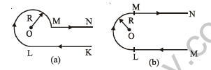
2. Find the magnetic induction at the point O if a wire carrying current I has the shape shown in figure (a, b). The radius of the curved part of the wire is R and the linear parts may be assumed to be very long.
(a)
Answer:
1. The curved part is three-quarters of a circle of radius R, carried from L round the left side and top to M (clockwise about O). Its field at O is \( \frac{3}{4} \cdot \frac{\mu_0 I}{2R} = \frac{3\mu_0 I}{8R} \), into the page.
2. The wire KL is a semi-infinite straight wire starting at L, which is at perpendicular distance R from O. Its field at O is \( \frac{\mu_0 I}{4\pi R} \), into the page.
3. The wire MN lies along the line through O, so it contributes zero field at O.
4. Total: B = \( \frac{\mu_0 I}{4\pi R} + \frac{3\mu_0 I}{8R} = \frac{\mu_0 I}{4\pi R}\left(1 + \frac{3\pi}{2}\right) \), into the page.
Teacher's Note:
a) A three-quarter arc gives three-quarters of the full-loop field μ₀I/(2R).
b) A straight wire that lies on a line passing through O gives no field at O; this is the MN part here.
c) A semi-infinite wire gives half of the field of a long straight wire at its perpendicular foot.
(b)
Answer:
1. The semicircular part (from L to M, clockwise about O) gives \( \frac{\mu_0 I}{4R} \), into the page.
2. The top straight wire starts at M, which is at perpendicular distance R from O. It is semi-infinite and gives \( \frac{\mu_0 I}{4\pi R} \), into the page.
3. The bottom straight wire starts at L, also at distance R from O, and gives \( \frac{\mu_0 I}{4\pi R} \), into the page.
4. Total: B = \( \frac{\mu_0 I}{4R} + \frac{2\mu_0 I}{4\pi R} = \frac{\mu_0 I}{4\pi R}(\pi + 2) \), into the page.
Teacher's Note:
a) A semicircle gives half the field of a full loop, which is μ₀I/(4R).
b) Both straight wires are semi-infinite, so each gives only μ₀I/(4πR).
c) Keep the common factor μ₀I/(4πR) outside the bracket to avoid errors.
3. A particle of mass 9 × 10⁻³¹ kg and negative charge of 1.6 × 10⁻¹⁹ coulomb is projected horizontally with a velocity of 10⁶ m/sec into a region between two infinite horizontal parallel plates of metal. The distance between the plates is 0.3 cm and the particle enters 0.1 cm below the top plate. The top and bottom plates are connected respectively to the positive and negative terminals of a 30 volt battery. Find the components of the velocity just before the particle hits one of the plates.
Answer:
1. Field between the plates: E = \( \frac{V}{d} = \frac{30}{0.3 \times 10^{-2}} \) = 1.0 × 10⁴ V/m, directed from the top plate to the bottom plate, that is, downward.
2. The particle is negative, so the electric force is upward: F = qE = 1.6 × 10⁻¹⁹ × 1.0 × 10⁴ = 1.6 × 10⁻¹⁵ N.
3. Upward acceleration: a = \( \frac{F}{m} = \frac{1.6 \times 10^{-15}}{9 \times 10^{-31}} \) ≈ 1.78 × 10¹⁵ m/s².
4. Distance to the top plate: 0.1 cm = 1.0 × 10⁻³ m. Vertical velocity on reaching it: vy = √(2ad) = √(2 × 1.78 × 10¹⁵ × 1.0 × 10⁻³) ≈ 1.89 × 10⁶ m/s, upward.
5. The horizontal component is not affected by the vertical field, so vx = 10⁶ m/s.
6. Hence, just before hitting the top plate, vx = 10⁶ m/s (horizontal) and vy ≈ 1.89 × 10⁶ m/s (upward).
Teacher's Note:
a) The field is V/d, and d must be in metres, so 0.3 cm becomes 3 × 10⁻³ m.
b) A negative charge is pushed against the field, so it moves toward the positive top plate.
c) The printed key gives 1.88 × 10⁶ m/s; the exact value is 1.886 × 10⁶ m/s, which rounds to 1.89 × 10⁶ m/s.
4. A non-relativistic proton beam passed without deviation through a region of space where there are mutually perpendicular uniform electric and magnetic fields with E = 120 kV/m and B = 50 mT. Then the beam strikes a ground target. Find the force with which the beam acts on the target if the beam current is equal to 0.8 mA.
Answer:
1. For no deflection, the electric and magnetic forces balance: qE = qvB, so v = \( \frac{E}{B} = \frac{120 \times 10^{3}}{50 \times 10^{-3}} \) = 2.4 × 10⁶ m/s.
2. Number of protons striking the target per second: n = \( \frac{I}{e} = \frac{0.8 \times 10^{-3}}{1.6 \times 10^{-19}} \) = 5 × 10¹⁵ per second.
3. Momentum of each proton: p = mv = 1.67 × 10⁻²⁷ × 2.4 × 10⁶ ≈ 4.0 × 10⁻²¹ kg m/s.
4. Force on the target = rate of momentum delivered: F = np = 5 × 10¹⁵ × 4.0 × 10⁻²¹ ≈ 2.0 × 10⁻⁵ N, along the beam.
Teacher's Note:
a) Undeflected motion means the two forces balance, so the speed is E/B and does not depend on the mass.
b) Convert kV/m to V/m and mT to T before dividing.
c) The printed key shows 2.04 × 10⁻⁵ N, which corresponds to taking the proton mass as 1.7 × 10⁻²⁷ kg; the answer is 2.0 × 10⁻⁵ N with the standard proton mass.
5. Two long parallel wires of zero resistance are connected to each other by a battery of 1.0 V. The separation between the wires is 0.5 m. A metallic bar, which is perpendicular to the wires and of resistance 10Ω, moves on these wires when a magnetic field of 0.02 Tesla is acting perpendicular to the plane containing the bar and the wires. Find the steady state velocity of the bar. If the mass of the bar is 0.002 kg, find its velocity as a function of time.
Answer:
1. Steady state: the current in the bar stops when the motional emf Blv equals the battery emf V, so v = \( \frac{V}{Bl} = \frac{1.0}{0.02 \times 0.5} \) = 100 m/s.
2. At time t, the current is I = \( \frac{V - Blv}{R} \), and the magnetic force on the bar opposes its motion: m \( \frac{dv}{dt} \) = \( \frac{Bl(V - Blv)}{R} \).
3. Time constant: τ = \( \frac{mR}{B^2 l^2} = \frac{0.002 \times 10}{(0.02)^2 (0.5)^2} \) = 200 s.
4. Solving with v = 0 at t = 0: v = \( \frac{V}{Bl}\left(1 - e^{-t/\tau}\right) \) = 100(1 − e−t/200) m/s.
5. For very small t, this gives v ≈ 0.5 t m/s, the initial straight-line rise.
Teacher's Note:
a) At steady state the induced emf cancels the battery emf, so no current flows through the bar.
b) The printed v = 0.5 t holds only for small times, because the acceleration falls as the speed rises.
c) The bar approaches 100 m/s exponentially, with a time constant of 200 s.
6. A galvanometer having 30 divisions has a current sensitivity of 20 μA/ division. It has a resistance of 25 ohm. How will you convert in into an ammeter measuring upto 1 ampere? How will you now convert this ammeter into a voltmeter reading upto 1 volt?
Answer:
1. Full-scale current of the galvanometer: Ig = 30 × 20 μA = 6 × 10⁻⁴ A.
2. Shunt for a 1 A ammeter, connected in parallel with the galvanometer: S = \( \frac{I_g G}{I - I_g} = \frac{6 \times 10^{-4} \times 25}{1 - 6 \times 10^{-4}} \) ≈ 0.015 Ω (1.5 × 10⁻² Ω).
3. Resistance of this ammeter: RA ≈ 0.015 Ω.
4. For a 1 V voltmeter, the total resistance must be \( \frac{1 \text{ V}}{1 \text{ A}} \) = 1 Ω, so a series resistance of 1 Ω − 0.015 Ω = 0.985 Ω is connected in series with the ammeter.
Teacher's Note:
a) The full-scale current is the number of divisions multiplied by the sensitivity per division.
b) The shunt carries the excess current, which is 1 A minus 6 × 10⁻⁴ A.
c) The series resistance for the voltmeter is found after subtracting the ammeter's own resistance, not from V/I alone.
7. Two straight infinitely long and thin parallel wires are spaced 0.1 m apart and carry a current of 10 ampere each. Find the magnetic field at a point distant 0.1 m from both wires in the two cases when the currents are in the
(a) same and
Answer:
1. Field of one wire at the point: B = \( \frac{\mu_0 I}{2\pi r} = \frac{2 \times 10^{-7} \times 10}{0.1} \) = 2 × 10⁻⁵ T.
2. The point and the two wires form an equilateral triangle, so the two fields make an angle of 60° with each other.
3. For currents in the same direction, the resultant is along the line joining the wires: B = 2B cos 30° = 2 × 2 × 10⁻⁵ × 0.866 ≈ 3.46 × 10⁻⁵ T.
Teacher's Note:
a) Each wire gives the same magnitude at the point because both are at the same distance.
b) Use the cosine of half the angle between the two fields when adding them.
c) The resultant lies along the line joining the two wires for parallel currents in the same direction.
(b) opposite directions.
Answer:
1. Each wire still gives 2 × 10⁻⁵ T at the point, with the fields at 60° to each other.
2. For currents in opposite directions, one field is reversed, and the resultant is perpendicular to the line joining the wires.
3. Resultant: B = 2 × 10⁻⁵ T, perpendicular to the line joining the two wires.
Teacher's Note:
a) Reversing one current reverses only that wire's field, which changes the direction of the resultant.
b) The magnitude is 2 × 10⁻⁵ T, which is smaller than the same-direction case.
8. In the Bohr model of hydrogen atom, the electron circulates around the nucleus in the path of radius 5.1 × 10⁻¹¹ m at a frequency of 6.8 × 10¹⁵ rev/s.
(a) Calculate the magnetic induction B at the centre of the orbit.
Answer:
1. Equivalent current: I = ef = 1.6 × 10⁻¹⁹ × 6.8 × 10¹⁵ = 1.088 × 10⁻³ A.
2. Field at the centre: B = \( \frac{\mu_0 I}{2r} = \frac{4\pi \times 10^{-7} \times 1.088 \times 10^{-3}}{2 \times 5.1 \times 10^{-11}} \).
3. B ≈ 13.4 T (Wb/m²).
Teacher's Note:
a) A revolving electron is an electric current equal to its charge times its revolutions per second.
b) The radius goes into the formula directly, in metres.
c) The answer is in tesla, which is the same unit as Wb/m².
(b) What is the equivalent dipole moment?
Answer:
1. Magnetic dipole moment: M = IA = I πr².
2. M = 1.088 × 10⁻³ × π × (5.1 × 10⁻¹¹)² ≈ 8.89 × 10⁻²⁴ A m².
Teacher's Note:
a) The dipole moment uses the square of the radius, not the diameter.
b) The printed key shows 8.88 × 10⁻²⁴ A m², which differs only in the last rounded digit; 8.89 × 10⁻²⁴ A m² is the value from the given data.
9. The wire loop PQRSP formed by joining two semi-circular wires of radii R1 and R2 carries a current I as shown in Fig. What is the magnetic induction at the centre O and magnetic moment of the loop in cases (A) and (B)?

(A)
Answer:
1. The outer semicircle (radius R2, from S over the top to P) is traversed clockwise, giving \( \frac{\mu_0 I}{4R_2} \) into the page.
2. The inner semicircle (radius R1, from Q over the top to R) is traversed anticlockwise, giving \( \frac{\mu_0 I}{4R_1} \) out of the page.
3. The straight parts lie along the diameter through O, so they give zero field at O.
4. Net field at O: B = \( \frac{\mu_0 I}{4}\left(\frac{1}{R_1} - \frac{1}{R_2}\right) \), out of the page.
5. Magnetic moment: M = I × (area of outer semicircle − area of inner semicircle) = \( \frac{\pi I (R_2^2 - R_1^2)}{2} \), into the page.
Teacher's Note:
a) A semicircular loop gives half the field of a full loop, which is μ₀I/(4R) at its centre.
b) The two arcs circulate in opposite senses, so their fields subtract.
c) The moment is the current times the area enclosed, and the area is the difference of the two half-discs.
(B)
Answer:
1. Both semicircular arcs are traversed in the same sense (clockwise), so each gives a field into the page at O.
2. Larger arc (radius R1): \( \frac{\mu_0 I}{4R_1} \), into the page. Smaller arc (radius R2): \( \frac{\mu_0 I}{4R_2} \), into the page.
3. The straight parts pass through O and give zero field.
4. Net field at O: B = \( \frac{\mu_0 I}{4}\left(\frac{1}{R_1} + \frac{1}{R_2}\right) \), into the page.
5. Magnetic moment: M = I × (πR1²/2 + πR2²/2) = \( \frac{\pi I (R_1^2 + R_2^2)}{2} \), into the page.
Teacher's Note:
a) When both arcs circulate the same way, their fields add at the centre.
b) The moment adds the areas of both semicircles because the loop encloses both.
c) The formulas are symmetric in R1 and R2, so the labels do not change the answer.
10. A loop of flexible conducting wire of length 0.5 m lies in a magnetic field of 1.0 Tesla perpendicular to the plane of the loop. Calculate the ten sion developed in the wire if the current is of 1.57 ampere.
Answer:
1. Circumference 2πr = 0.5 m, so r = \( \frac{0.5}{2\pi} \) ≈ 0.0796 m.
2. Consider half of the loop. The magnetic force on it is BI × (diameter) = BI × 2r, pointing outward.
3. This force is balanced by the tensions at the two ends of the half-loop, 2T: 2T = BI(2r), so T = BIr.
4. T = 1.0 × 1.57 × 0.0796 ≈ 0.125 N.
Teacher's Note:
a) The net force on a semicircle of wire equals the field times the current times the diameter.
b) Since 2πr = L, the tension can also be written as BIL/(2π).
c) Tension acts along the wire, so each half of the loop pulls on the other.
11. A coil in the shape of an equilateral triangle of side 0.02 m is suspended from a vertex such that it is hanging in a vertical plane between the pole pieces of a permanent magnet producing a horizontal magnetic field of 5 × 10⁻² T. Find the couple acting on the coil when a current of 0.1 ampere is passed through it and the magnetic field is parallel to its plane.
Answer:
1. Area of the equilateral triangle: A = \( \frac{\sqrt{3}}{4} a^2 = \frac{\sqrt{3}}{4} (0.02)^2 \) ≈ 1.73 × 10⁻⁴ m².
2. Magnetic moment of the coil: M = IA = 0.1 × 1.73 × 10⁻⁴ ≈ 1.73 × 10⁻⁵ A m², normal to the plane of the coil.
3. The field lies in the plane of the coil, so the angle between M and B is 90°.
4. Couple: τ = MB sin 90° = 1.73 × 10⁻⁵ × 5 × 10⁻² ≈ 8.66 × 10⁻⁷ N m, which is exactly 5√3 × 10⁻⁷ N m.
Teacher's Note:
a) The couple on a coil is MB sin θ, where θ is the angle between the moment and the field.
b) The moment is perpendicular to the plane, so an in-plane field gives the maximum couple.
c) Keep the exact value 5√3 × 10⁻⁷ N m in the answer, and round only at the end.
12. The magnetic field existing in a region is given by B = B₀ (1 + \( \frac{x}{l} \)) k̂. A square loop of edge l and carrying a current i, is placed with its edges parallel to the X - Y axes. Find the magnitude of the net magnetic force experienced by the loop
Answer:
1. The field depends only on x, so the two sides parallel to the X-axis (at y = 0 and y = l) carry equal and opposite forces, which cancel.
2. Side at x = 0: B = B₀, and the force on it is i l B₀, along −X.
3. Side at x = l: B = 2B₀, and the force on it is i l (2B₀) = 2 i l B₀, along +X.
4. Net force: F = 2 i l B₀ − i l B₀ = i B₀ l, along the X-axis.
Teacher's Note:
a) A uniform field gives zero net force on a closed loop, so the net force comes only from the change in B across the loop.
b) The net force equals i times the difference of B across the loop times l, which is i B₀ l here.
c) The direction is along the X-axis, toward the region of stronger field, for the current sense shown in the figure.
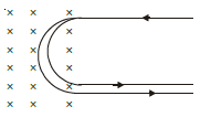
13. A narrow beam of singly charged carbon ions, moving at a constant velocity of 6.0 × 10⁴ m/s, is sent perpendicularly in a rectangular region having uniform magnetic field B = 0.5 T. It is found that two beams emerge from the field in the backward direction, the separations from the incident beam being 3.0 cm and 3.5 cm. Identify the isotopes present in the ion beam. Take the mass of an ion = A(1.6 × 10⁻²⁷) kg, where A is the mass number.
[Figure: Region shaded with crosses (magnetic field into the page) on the left. The incident beam is the upper horizontal line with an arrow pointing left, entering a semicircular path inside the field. Two emerging beams, the lower two horizontal lines with arrows pointing right, leave the field in the backward direction, at separations of 3.0 cm and 3.5 cm from the incident beam.]
Answer:
1. Radius of the circular path: r = \( \frac{mv}{qB} \), where q = e = 1.6 × 10⁻¹⁹ C.
2. Separation from the incident beam is the diameter of the semicircle, so r = \( \frac{d}{2} \).
3. Mass number: A = \( \frac{eBr}{v \times 1.6 \times 10^{-27}} = \frac{1.6 \times 10^{-19} \times 0.5 \times r}{6.0 \times 10^{4} \times 1.6 \times 10^{-27}} \) ≈ 833 r, with r in metres.
4. For d = 3.0 cm, r = 0.015 m, A ≈ 12.5. For d = 3.5 cm, r = 0.0175 m, A ≈ 14.6.
5. Predicted separations: for carbon-12, d = 2 × 1.44 cm = 2.88 cm; for carbon-14, d = 2 × 1.68 cm = 3.36 cm.
6. Hence, the two isotopes present are carbon-12 and carbon-14.
Teacher's Note:
a) The beam returns along a semicircle, so the separation equals the diameter 2r.
b) The mass is found from r = mv/(qB), and the mass number is the mass divided by 1.6 × 10⁻²⁷ kg.
c) The separations are read only to about 0.5 cm, so the mass numbers are approximate and match C-12 and C-14.
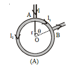
14. A battery is connected between two points A and B on the circumference of a uniform conducting ring of radius r and resistance R as shown in Fig. One of the arcs AB of the ring subtends an angle θ at the centre. What is the value of the magnetic field at the centre due to the current in the ring?
Answer:
1. The two arcs of the ring act as parallel branches between A and B. Arc AB (angle θ) has resistance \( \frac{R\theta}{2\pi} \), and the other arc (angle 2π − θ) has resistance \( \frac{R(2\pi - \theta)}{2\pi} \).
2. Currents: I1 = \( \frac{V}{R\theta/2\pi} \) and I2 = \( \frac{V}{R(2\pi-\theta)/2\pi} \).
3. Field at the centre due to an arc of angle φ carrying current I is \( \frac{\mu_0 I \varphi}{4\pi r} \). For the first arc: \( \frac{\mu_0 I_1 \theta}{4\pi r} = \frac{\mu_0}{4\pi r} \cdot \frac{2\pi V}{R} \).
4. For the second arc: \( \frac{\mu_0 I_2 (2\pi - \theta)}{4\pi r} = \frac{\mu_0}{4\pi r} \cdot \frac{2\pi V}{R} \), the same magnitude.
5. The two arcs carry current in opposite senses around the ring, so the two fields are equal and opposite. Net field at the centre: B = 0.
Teacher's Note:
a) The current divides between the arcs in inverse proportion to their resistances.
b) The product of current and angle is the same for both arcs, which is why the fields cancel exactly.
c) The result is zero for any angle θ, not only for a symmetric position of A and B.
15. A solenoid of length 0.4 m and having 500 turns of wire carries a current of 3 ampere. A thin coil having 10 turns of wire and of radius 0.01 m carries a current of 0.4 ampere. Calculate the torque required to hold the coil in the middle of the solenoid with its axis perpendicular to the axis of the solenoid.
Answer:
1. Turns per metre of the solenoid: n = \( \frac{500}{0.4} \) = 1250 m⁻¹.
2. Field inside the solenoid: B = μ₀nI = 4π × 10⁻⁷ × 1250 × 3 ≈ 4.71 × 10⁻³ T.
3. Magnetic moment of the small coil: M = NIA = 10 × 0.4 × π(0.01)² ≈ 1.26 × 10⁻³ A m².
4. The coil axis is perpendicular to the solenoid axis, so the angle between M and B is 90°.
5. Torque: τ = MB sin 90° = 1.26 × 10⁻³ × 4.71 × 10⁻³ ≈ 5.9 × 10⁻⁶ N m.
Teacher's Note:
a) The field inside a long solenoid is uniform and equals μ₀nI, where n is turns per metre.
b) Use turns per metre, not the total number of turns, when finding the field.
c) The torque is largest when the coil's axis is perpendicular to the field and zero when the axes are parallel.
16. An electron beam passes through a magnetic field of 2 × 10⁻³ Wb/m² and an electric field of 3.4 × 10⁴ V/m, both acting simultaneously. If the path of electrons remains undeflected, calculate the speed of the electrons. If the electric field is removed, what will be the radius of the electron path [me = 9.1 × 10⁻³¹ kg]?
Answer:
1. For no deflection: eE = evB, so v = \( \frac{E}{B} = \frac{3.4 \times 10^{4}}{2 \times 10^{-3}} \) = 1.7 × 10⁷ m/s.
2. With the electric field removed, the electron moves in a circle: r = \( \frac{m_e v}{eB} = \frac{9.1 \times 10^{-31} \times 1.7 \times 10^{7}}{1.6 \times 10^{-19} \times 2 \times 10^{-3}} \).
3. r ≈ 4.83 × 10⁻² m = 4.83 cm.
Teacher's Note:
a) The speed from balanced forces does not depend on the mass or the charge of the electron.
b) Use e = 1.6 × 10⁻¹⁹ C in the radius formula, as the mass is given in kg.
c) The radius comes out in metres, so 0.0483 m must be written as 4.83 cm.
17. A pair of stationary and infinitely long bent wires are placed in the xy plane as shown in figure. The wires carry currents of i = 10 A each as shown. The segments L and M are along the x-axis. The segments P and Q are parallel to the y-axis such that OS = OR = 0.02 m. Find the magnitude and direction of the magnetic induction at the origin O.
Answer:
1. Segments L and M lie along the x-axis, which passes through O, so they give zero field at O.
2. Segment P is a semi-infinite wire starting at R, which is at distance a = 0.02 m from O. Its field at O is \( \frac{\mu_0 i}{4\pi a} \), out of the page.
3. Segment Q is a semi-infinite wire starting at S, also at distance a = 0.02 m. Its field at O is \( \frac{\mu_0 i}{4\pi a} \), out of the page.
4. Total: B = \( \frac{\mu_0 i}{2\pi a} = \frac{4\pi \times 10^{-7} \times 10}{2\pi \times 0.02} \) = 1 × 10⁻⁴ T = 1 gauss, along +z, that is, out of the plane of the paper.
Teacher's Note:
a) A wire lying on a line through the point gives no field at that point.
b) Each vertical half-wire gives half of the field of an infinite straight wire, μ₀i/(2πa).
c) One gauss equals 10⁻⁴ T.
18. Calculate the magnetic induction at the centre of a rectangular frame of wire carrying a current I. The length of any diagonal of the rectangular frame is d and the acute angle between its diagonals is φ.
Answer:
1. Let the sides be a and b. Each side subtends the angle φ or (π − φ) at the centre, so a = d sin(φ/2) and b = d cos(φ/2).
2. A finite straight side of length a at distance b/2 from the centre gives Ba = \( \frac{\mu_0 I a}{\pi b d} \), and the side b gives Bb = \( \frac{\mu_0 I b}{\pi a d} \). All four sides add in the same sense.
3. Total: B = 2(Ba + Bb) = \( \frac{2\mu_0 I}{\pi d}\cdot\frac{a^2 + b^2}{ab} \).
4. Since a² + b² = d² and ab = \( \frac{d^2 \sin\phi}{2} \), we get \( \frac{a^2 + b^2}{ab} = \frac{2}{\sin\phi} \).
5. Hence B = \( \frac{4\mu_0 I}{\pi d \sin\phi} \).
Teacher's Note:
a) Two sides of a rectangle are related to the diagonal by sine and cosine of half the angle between diagonals.
b) The distance from the centre to each side is half of the other side's length.
c) Check with a square of side s: d = s√2 and φ = 90°, which gives 2√2 μ₀I/(πs), the known result.
19. In figure, MN is a very long wire which carries a current I1 along the x-axi white PQ is a straight segment of another wire lying along the y-axis and carrying a current I2. The strength PQ = L and OP = d, with OP ⊥ MN. Calculate the magnitude and direction of (a) the force F experienced by PQ and (b) the torque experienced by PQ about the axis MN.
(a) the force F experienced by PQ
Answer:
1. Field of the long wire MN at a distance y from it along PQ: B = \( \frac{\mu_0 I_1}{2\pi y} \), perpendicular to the plane of MN and PQ.
2. Force on a small length dy of PQ: dF = I2 dy × B, which is directed along MN.
3. F = \( \int_d^{d+L} \frac{\mu_0 I_1 I_2}{2\pi y}\, dy = \frac{\mu_0 I_1 I_2}{2\pi} \ln\left(\frac{d+L}{d}\right) \), along the x-axis, from M towards N.
Teacher's Note:
a) The field of an infinite straight wire is μ₀I/(2πr), so the denominator has 2π.
b) The force on PQ is parallel to MN, so the two wires are not pulling it across.
c) The printed key shows 4π in the denominator; the field formula gives 2π, which is used here.
(b) the torque experienced by PQ about the axis MN.
Answer:
1. Each element of PQ is pushed along MN, so the moment of this force about the axis MN itself is zero.
2. The non-zero torque is about an axis through O perpendicular to the plane of MN and PQ (the z-axis). Torque on the element: dτ = y dF = \( \frac{\mu_0 I_1 I_2}{2\pi} dy \).
3. Integrating from y = d to y = d + L: τ = \( \frac{\mu_0 I_1 I_2 L}{2\pi} \).
Teacher's Note:
a) A force parallel to an axis produces no torque about that axis, so the torque about MN is zero.
b) The value μ₀I₁I₂L/(2π) is the torque about an axis through O perpendicular to the plane, which is the printed key's value.
20. A parallel plate capacitor having plate area equal to A and the separation between the plates equal to d, is placed in a stream of conducting liquid with resistivity ρ. The liquid moves with constant velocity v parallel to the plates of capacitor. The complete system is placed in a uniform magnetic field of induction B, which is parallel to the plates of capacitor and perpendicular to direction of motion of liquid. The plates of capacitor are joined by some external resistance R. Calculate the amount of power generated in that resistance.
Answer:
1. Motional emf of the liquid between the plates: ε = Bvd, because v, B and d are mutually perpendicular.
2. Resistance of the liquid between the plates: r = \( \frac{\rho d}{A} \).
3. Current through the circuit: I = \( \frac{Bvd}{R + \rho d/A} \).
4. Power in the external resistance: P = I²R = \( \frac{B^2 v^2 d^2 R}{\left(R + \frac{\rho d}{A}\right)^2} \).
Teacher's Note:
a) The emf depends on the plate separation d, not on the plate area.
b) The liquid between the plates acts as an internal resistance in series with R.
c) The power in R is largest when R equals ρd/A, which is the matching condition.
Free study material for Physics
CBSE Class 12 Physics Study Material: Chapter 01 Electric Charges and Fields
Quick Revision Material for Chapter 01 Electric Charges and Fields
Access comprehensive study material for Chapter 01 Electric Charges and Fields, including revision notes, concept maps, and high-probability questions. These resources are designed in alignment with the latest 2026 CBSE syllabus for Class 12 Physics to support effective exam preparation.
Expert Notes and Solved Exam Questions
Built using official NCERT guidelines for Class 12 Physics, these materials provide reliable academic support. Integrating past examination questions and step-by-step solutions helps students understand official CBSE grading criteria.
Additional Study Resources for Class 12
Maximize your grade potential by utilizing Class 12 Physics practice papers in tandem with these structured notes. All printable assignments and interactive mock tests on our platform are updated for the 2026 session and available free of charge.
FAQs
Our advanced study package for Chapter 01 Electric Charges and Fields includes detailed concepts, diagrams, Mind Maps, and explanation of complex topics to ensure Class 12 students learn as per syllabus for 2026 exams.
The Mind Maps provided for Chapter 01 Electric Charges and Fields act as visual anchors which will help faster recall during high-pressure exams.
Yes, teachers use our Class 12 Physics resources for lesson planning as they are in simple language and have lot of solved examples.
Yes, You can download the complete, mobile-friendly PDF of the Physics Chapter 01 Electric Charges and Fields advanced resources for free.
Yes, our subject matter experts have updated the Chapter 01 Electric Charges and Fields material to align with the rationalized NCERT textbooks and have removed deleted topics and added new competency-based questions.