

Official CBSE Study Materials for Class 12 Physics
Review targeted academic resources with the CBSE Class 12 Physics Electromagnetic Induction Theory and Examples. Built according to official CBSE standards for the 2026-27 term, these downloadable Class 12 Physics study materials support effective daily practice and deeper conceptual understanding for Chapter 06 Electromagnetic Induction.
Advanced Resources for Physics
Navigate directly to the advanced Physics study materials using the digital viewer below. Each resource pack includes detailed conceptual summaries and solved practice questions, allowing students to instantly reinforce their learning.
CBSE Class 12 Physics Electromagnetic Induction Theory and Examples. Please refer to the examination notes which you can use for preparing and revising for exams. These notes will help you to revise the concepts quickly and get good marks.
ELECTROMAGNETIC INDUCTION
ELECTROMAGNETIC INDUCTION
1. MAGNETIC FLUX
- The number of lines of flux passing through an area held perpendicular to the field is equal to the magnetic flux linked with that plane.
- Mathematically, magnetic flux is the product of the field and the area of the plane, i.e. \(\phi=\vec B\cdot\vec A=BA\cos\theta\), where \(\theta\) is the angle between the magnetic induction and the area vector (the area vector is perpendicular to the plane of the area).
- It is a scalar quantity.
- Unit: MKS – weber or tesla-m2 (or N·m/A); CGS – maxwell or gauss-cm2. \(1\ \text{weber}=1\ \text{tesla-m}^2=10^8\ \text{maxwell}=10^8\ \text{gauss-cm}^2\).

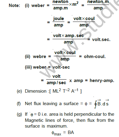

Note:
- \(\text{weber}=\dfrac{\text{newton}}{\text{amp}\cdot\text{m}}\times\text{m}^2=\dfrac{\text{newton}\cdot\text{m}}{\text{amp}}=\dfrac{\text{joule}}{\text{amp}}=\dfrac{\text{volt}\times\text{coul}}{\text{amp}}=\dfrac{\text{volt}\times\text{amp}\cdot\text{sec}}{\text{amp}}=\text{volt-sec}\)
- \(\text{weber}=\dfrac{\text{volt}\times\text{coul}}{\text{amp}}=\text{ohm-coul}\)
- \(\text{weber}=\text{volt-sec}=\dfrac{\text{volt}}{\text{amp/sec}}\times\text{amp}=\text{henry-amp}\)
- Dimension: \([ML^2T^{-2}A^{-1}]\).
- Net flux leaving a surface \(=\phi=\oint\vec B\cdot d\vec s\).
- If \(\theta=0\), i.e. the area is held perpendicular to the magnetic lines of force, then the flux through the surface is maximum: \(\phi_{max}=BA\).
- If \(\theta=90^\circ\), i.e. the area is held parallel to the lines of force, then the flux through the surface is zero: \(\phi=BA\cos90^\circ=0\).
- Net flux linked with a closed surface is zero: \(\phi=\oint\vec B\cdot d\vec s=0\). Why? Magnetic lines of force are closed curves, so the number of lines entering a closed surface is equal to the number of lines leaving the surface. Hence the net flux is 0.
- Flux linked with a surface depends on the following quantities: (i) intensity of the magnetic field \(B\); (ii) area of the surface \(A\); (iii) orientation of the surface relative to the magnetic field.
At a certain location in the northern hemisphere, the earth’s magnetic field has a magnitude of 42 μT and points downward at 57° to the vertical. The flux through a horizontal surface of area 2.5 m2 will be: (given \(\cos33^\circ=0.839\), \(\cos57^\circ=0.545\))
- \(42\times10^{-6}\) Wb
- \(42\times10^{-6}\) Wb/m2
- \(57\times10^{-6}\) Wb
- \(57\times10^{-6}\) Wb/m2
Answer: (C)
The flux through the area is
\[\phi=BA\cos57^\circ=42\times10^{-6}\times2.5\times0.545=57\times10^{-6}\ \text{Wb}\]
2. FARADAY’S LAWS OF ELECTROMAGNETIC INDUCTION
- Whenever the number of magnetic lines of force (magnetic flux) passing through a circuit changes, an e.m.f. is produced in the circuit, called the induced e.m.f.
- If the circuit is closed, a current flows through it, called the induced current.
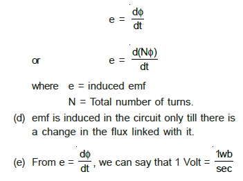
- The induced e.m.f. is given by the rate of change of magnetic flux linked with the circuit, i.e. \(e=\dfrac{d\phi}{dt}\) or \(e=\dfrac{d(N\phi)}{dt}\), where \(e\) = induced e.m.f. and \(N\) = total number of turns.
- An e.m.f. is induced in the circuit only as long as there is a change in the flux linked with it.
- From \(e=\dfrac{d\phi}{dt}\) we can say that \(1\ \text{volt}=1\ \text{wb/sec}\).
3. LENZ’S LAW
- This gives the direction of the induced e.m.f.
- According to this law, the direction of the induced e.m.f. or current is such as to oppose the change that produces it.
- From Lenz’s law and Faraday’s law, the induced e.m.f. is given by \(e=-\dfrac{d\phi}{dt}\), where the minus sign shows that the e.m.f. opposes the change of flux linked with it.
- This law is based upon the law of conservation of energy.
- Mechanical energy and magnetic energy get converted into electrical energy in this phenomenon, called electromagnetic induction.

Problems:
(i) A square loop is moved through a region of uniform magnetic field (directed into the page). While it enters the field the magnetic flux through the square is increasing; when it is completely inside there is no change in the magnetic flux and the current is zero (i = 0); while it leaves the region the flux is decreasing.
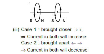
(ii) Two coaxial loops carrying current in the same sense (shown in the figure; the magnetic faces are S N and S N):
Case 1: brought closer \(\to\leftarrow\) \(\Rightarrow\) the current in both will decrease. Case 2: brought apart \(\leftarrow\to\) \(\Rightarrow\) the current in both will increase.
(iii) For two coaxial loops carrying currents in opposite senses: Case 1: brought closer \(\to\leftarrow\) \(\Rightarrow\) the current in both will increase. Case 2: brought apart \(\leftarrow\to\) \(\Rightarrow\) the current in both will decrease.
A coil of metal wire is kept stationary in a non-uniform magnetic field. Is there any induced e.m.f. in the coil?
Answer: No, since the magnetic flux is not changing.
4. SOME GENERAL POINTS
- The induced e.m.f. is given by \(e=-\dfrac{d\phi}{dt}\). The sign is given by Lenz’s law.
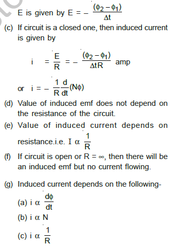
- If the magnetic flux linked with a circuit changes from \(\phi_1\) to \(\phi_2\) in time \(\Delta t\), then the induced e.m.f. is \(E=-\dfrac{\phi_2-\phi_1}{\Delta t}\).
- If the circuit is a closed one, then the induced current is given by \(i=\dfrac ER=-\dfrac{\phi_2-\phi_1}{\Delta t\,R}\) amp, or \(i=-\dfrac1R\dfrac{d}{dt}(N\phi)\).
- The value of the induced e.m.f. does not depend on the resistance of the circuit.
- The value of the induced current depends on the resistance, i.e. \(I\propto\dfrac1R\).
- If the circuit is open or \(R=\infty\), then there will be an induced e.m.f. but no current flowing.
- The induced current depends on the following: (a) \(i\propto\dfrac{d\phi}{dt}\); (b) \(i\propto N\); (c) \(i\propto\dfrac1R\).
- If a charge \(dq\) flows due to induction in time \(dt\), then \(i=\dfrac{dq}{dt}=\dfrac1R\dfrac{d\phi}{dt}\Rightarrow dq=\dfrac{d\phi}{R}\), so \(q=\dfrac1R\int d\phi=\dfrac{\phi_2-\phi_1}{R}\) (important).
- This flow of charge is called the induced charge.
- The charge induced does not depend on the time interval in which the flux through the circuit changes. It depends only on the net change in flux and the resistance of the circuit.
Examples: Induced e.m.f.
A rectangular coil of size 10 cm × 20 cm has 60 turns. It is rotating in a magnetic field of 0.5 Wb/m2 at a rate of 1800 revolutions per minute. The maximum induced e.m.f. across the ends of the coil is:
- 111 V
- 112 V
- 113 V
- 114 V
Answer: (C) 113 V
Given: area \(=10\times20\ \text{cm}^2=200\times10^{-4}\ \text{m}^2\), \(B=0.5\) T, \(N=60\), \(\omega=2\pi\times\dfrac{1800}{60}\).
\[e=-\frac{d(N\phi)}{dt}=-N\frac d{dt}(BA\cos\omega t)=NBA\omega\sin\omega t\]
\[e_{max}=NBA\omega=60\times2\times10^{-2}\times0.5\times2\pi\times\frac{1800}{60}=113\ \text{volt}\]
A closed coil of copper whose area is 1 m × 1 m is free to rotate about an axis. The coil is placed perpendicular to a magnetic field of 0.10 Wb/m2. It is rotated through 180° in 0.01 second. The induced e.m.f. and induced current in the coil will respectively be: (The resistance of the coil is 2.0 Ω)
- 20 V, 10 A
- 10 V, 20 A
- 10 V, 10 A
- 20 V, 20 A
Answer: (A)
The change in flux linked with the coil on rotating it through 180° is \(nAB-(-nAB)=2nAB\).
\[\text{induced e.m.f.}=-\frac{d\phi}{dt}=\frac{2nAB}{dt}\ \text{(numerically)}=\frac{2\times1\times0.1}{0.01}=20\ \text{V}\]
The coil is closed and has a resistance of 2.0 Ω. Therefore \(i=20/2=10\) A.
Note: when the coil is opened, the induced e.m.f. is still present in it but the induced current becomes zero.
A coil having 100 turns and area 0.001 m2 is free to rotate about an axis. The coil is placed perpendicular to a magnetic field of 1 Wb/m2. If the coil is rotated rapidly through an angle of 180°, the charge flown through the coil will be: (The resistance of the coil is 10 Ω.)
- 0.01 C
- 0.02 C
- 0.03 C
- 0.04 C
Answer: (B)
The flux linked with the coil, when the plane of the coil is perpendicular to the magnetic field, is \(\phi=nAB\cos\theta=nAB\). The change in flux on rotating the coil by 180° is \(d\phi=nAB-(-nAB)=2nAB\).
\[\text{induced charge}=\frac{d\phi}{R}=\frac{2nAB}{R}=\frac{2\times100\times0.001\times1}{10}=0.02\ \text{C}\]
5. DIRECTION OF INDUCED E.M.F. AND INDUCED CURRENT
(a) The various positions of relative motion between the magnet and the coil are represented in the following table (the current directions are those seen by an observer looking at the coil from the side of the magnet).
| Position of magnet | Deflection of galvanometer | Direction of current in coil | Behaviour of the face of the coil | Type of magnetic force opposed | Magnetic flux |
|---|---|---|---|---|---|
| The north pole of the magnet approaches the coil | Towards left | Anticlockwise | As a north pole | Repulsive force | Increases |
| The north pole of the magnet recedes away from the coil | Towards right | Clockwise | As a south pole | Attractive force | Decreases |
| The south pole of the magnet approaches the coil | Towards right | Clockwise | As a south pole | Repulsive force | Increases |
| The south pole of the magnet recedes away from the coil | Towards left | Anticlockwise | As a north pole | Attractive force | Decreases |
Representation of magnetic lines of force (column of the table above):
(b) When there is relative motion between two inductive circuits:
| Relative motion of circuits | Direction of induced current in the stationary circuit |
|---|---|
| When a current-carrying circuit is approached towards a stationary circuit. | The direction of the induced current in the stationary circuit is opposite to that in the moving circuit. |
| When a current-carrying circuit is moved away from the stationary circuit. | The direction of the induced current in the stationary circuit is the same as that in the moving circuit. |
(c) When there is an increase or decrease of current in current-carrying coils:
| Current in the coil | Direction of induced current in the coil |
|---|---|
| When the value of current is increased in the coil, then | The direction of the induced current in the coil will be in a direction opposite to that of the main current. |
| When the current flowing in the coil is decreased, then | The direction of the induced current in the coil will be the same as that of the main current. |
(d) When the inductive circuits are closed or opened: if two coils (primary and secondary) are arranged as shown (a primary circuit with battery \(\varepsilon_1\), resistance \(R_1\) and switch S, and a secondary coil with resistance \(R_2\)) and the circuit is closed or opened, then the direction of the induced current in them will be according to the following table.
| State of the circuit | When the circuit is closed, i.e. switch S is pressed | When the circuit is opened, i.e. the switch S is raised |
|---|---|---|
| Direction of induced current in the secondary coil | \(B\) increasing: the direction of the induced current in the secondary coil is opposite to that in the primary coil (\(I_1\) increasing, \(I_2\) induced). | \(B\) decreasing: the direction of the induced current in the secondary coil is the same as that in the primary coil (\(I_1\) decreasing, \(I_2\) induced). |
(e) When two coils are arranged as shown in the figure (a large coil P and a small coil Q at its centre, with a battery and key K in the circuit of P):
- When key K is closed, the current in P will flow in the clockwise direction and consequently the induced current in Q will flow in the anticlockwise direction.
- When key K is opened, the current in P falls from maximum to zero and consequently the induced current in Q will flow in the clockwise direction.
(f) When three coils are arranged coaxially as in the figure (coils P, Q and R, with an observer looking from the P side): equal currents are flowing in coils P and R as shown. Coils Q and R are fixed. Coil P is moved towards Q. The induced current in Q will be in the clockwise direction so that it may oppose the approach of P according to Lenz’s law. As the face of P towards Q is a south pole, the plane of Q towards P will also be a south pole. As there is no relative motion between Q and R, no current is induced in Q due to R.
(g) When the current in a straight conductor is increased:
- The direction of the induced current in the loop (placed with the wire CD below it) will be clockwise, so that it may oppose the increase of magnetic flux in the loop in the upward direction.
- The direction of the induced current in the loop (placed with the wire CD above it) will be anticlockwise, so that it may oppose the increase of magnetic flux in the loop in the downward direction.
(h) When a bar magnet is dropped vertically into a conducting coil:
- A current will be induced in the coil in the anticlockwise direction so that it may oppose the motion of the magnet and consequently its acceleration will be less than \(g\) (i.e. if the coil is small, then \(a<g\)).
- If the coil is broken at any point, then an induced e.m.f. will be generated in it but no induced current will flow. In this condition the coil will not oppose the motion of the magnet and the magnet will fall freely with acceleration \(g\) (i.e. \(a=g\)).
(i) When the magnet is dropped freely into a long vertical copper tube: the resistance of the copper tube is quite negligible (being a continuous medium) and hence maximum induced currents (eddy currents) are generated in it due to the motion of the magnet. Due to these eddy currents the motion of the magnet is also opposed maximum, consequently the acceleration of the magnet will be zero (\(a=g-g=0\)).
(j) When the magnet is dropped freely into a long solenoid of copper wire: because the resistance of a copper solenoid is much higher than that of a copper tube, the induced current in it, due to the motion of the magnet, will be much less than that in the tube. Consequently the opposition to the motion of the magnet will be less and the magnet will fall with an acceleration \(a\) less than \(g\) (i.e. \(a<g\)).
(k) A magnet is dropped from the ceiling along the axis of a metallic ring kept at ice temperature and then at room temperature. When this magnet is photographed with a time-sequence camera it is found that:
- When the metallic ring is at ice temperature, the magnet falls slowly, because at ice temperature the resistance of the ring is low and consequently more induced current is generated in it and the motion of the magnet is opposed more.
- When the metallic ring is at room temperature, the magnet falls faster, because in this condition the resistance of the ring will be higher and consequently less induced current will be generated in it and the motion of the magnet will be opposed less.
(l) Determination of the poles of a coil:
- If, on looking at the face of the coil, the direction of the current in it is anticlockwise, then that face of the coil will be a north pole.
- If, on looking towards the face of the coil, the direction of the current in it is clockwise, then that face of the coil will be a south pole.
- The face of the coil into which the magnetic lines of force merge behaves like a south pole (S).
- The face of the coil from which the magnetic lines of force emerge out behaves like a north pole.
- While looking towards the face of the coil into which the magnetic flux merges, the direction of the current in it is clockwise and hence that face of the coil behaves like a south pole (S).
- While looking towards the face of the coil from which the magnetic flux emerges, the direction of the current in it is anticlockwise and hence that face of the coil behaves like a north pole (N).
(m) When a magnetic pole is approached or receded away from a coil:
- When the north pole of a magnet is brought near a loop, then on looking from the other side of the loop, the direction of the induced current in it will be clockwise.
- When the south pole of a magnet is brought near a loop, then on looking from the other side of the loop, the direction of the induced current in it will be anticlockwise.
(n) When a circular ring is falling in the magnetic field of a current-carrying coil: in the position shown (ring above the coil) the upper face of the coil behaves like a south pole. According to Lenz’s law the lower face of the ring will behave like a south pole. Hence, looking from the upper side, the direction of the induced current will be anticlockwise.
(o) Other features related to induced e.m.f.:
- The induced e.m.f. depends on (A) \(A\), (B) \(N\), (C) \(\dfrac{dB}{dt}\).
- The direction of the induced e.m.f. depends on (A) the direction of the magnetic flux, (B) the rate of change of magnetic flux, i.e. whether \(\dfrac{d\phi}{dt}\) is positive or negative, increasing or decreasing.
- The conditions when an induced e.m.f. may be produced: (A) when there is relative motion between the coil and the magnet; (B) when a train runs in any direction, an e.m.f. will be induced between the ends of its axle due to the vertical component of the earth’s magnetic field; (C) when an aeroplane flies in the horizontal direction; (D) when a conducting wire is dropped freely in the east–west direction; (E) when the plane of the orbit of a metallic satellite is inclined at any angle from the equatorial plane; (F) when an aeroplane lands or takes off with its wings in the east–west direction.
- The conditions when an induced e.m.f. is not produced: (A) if there is no relative motion between the magnet and the coil; (B) when the magnet and the coil both move with the same velocity in the same direction; (C) when a conducting wire is freely dropped towards the earth in the north–south direction; (D) when the plane of the orbit of a metallic satellite coincides with the equatorial plane of the earth; (E) when an aeroplane lands or takes off with its wings in the north–south direction; (F) when an aeroplane flies along the direction of the earth’s magnetic field (e.g. northwards at the magnetic equator, where the field is horizontal); (G) when a conductor moves in the direction of the magnetic field.
- The conditions for the induced e.m.f. being maximum: (A) when the relative motion between the magnet and the coil is fast; (B) on placing a core of high permeability inside the coil; (C) on taking a stronger magnet; (D) on increasing the number of turns in the coil.
Examples
A current-carrying solenoid is approaching a conducting loop as shown in the figure. The direction of the induced current as observed by an observer on the other side of the loop will be:
- anticlockwise
- clockwise
- east
- west
Answer: (A)
The direction of the current in the solenoid is clockwise. On displacing it towards the loop, a current in the loop will be induced in the clockwise direction so as to oppose its approach. Therefore the direction of the induced current as observed by the observer will be anticlockwise.
Consider the arrangement in which the north pole of a magnet is moved away from a thick conducting loop containing a capacitor (plates a and b). Then excess positive charge will arrive on:
- plate a
- plate b
- both plates a and b
- neither plate a nor b
Answer: (B)
When the north pole of the magnet is moved away, a south pole is induced on the face of the loop in front of the magnet, i.e. as seen from the magnet side a clockwise induced current flows in the loop. This makes free electrons move in the opposite direction, to plate a. Thus excess positive charge appears on plate b. The correct answer is (B).
The current changes in an inductance coil of 100 mH from 100 mA to zero in 2 milliseconds. The e.m.f. induced in the coil will be:
- −5 V
- 5 V
- −50 V
- 50 V
Answer: (B)
\[E=-L\frac{dI}{dt}=-100\times10^{-3}\times\frac{(0-100)\times10^{-3}}{2\times10^{-3}}=5.0\ \text{V}\]
When a small piece of wire passes between the magnetic poles of a horse-shoe magnet in 0.1 sec, an e.m.f. of \(4\times10^{-3}\) volt is induced in it. The magnetic flux between the poles is:
- \(4\times10^{-2}\) weber
- \(4\times10^{-4}\) weber
- \(4\times10^{-3}\) weber
- \(4\times10^{-6}\) weber
Answer: (C) \(4\times10^{-4}\) weber (the PDF option order is (A) \(4\times10^{-2}\), (B) \(4\times10^{-3}\), (C) \(4\times10^{-4}\), (D) \(4\times10^{-6}\) weber)
\[E=\left|\frac{d\phi}{dt}\right|\ \Rightarrow\ d\phi=E\,dt\ \text{(in magnitude)}\]
\[\phi=4\times10^{-3}\times0.1=4\times10^{-4}\ \text{weber}\]
The normal magnetic flux passing through a coil changes with time according to the equation \(\phi=10t^2+5t+1\), where \(\phi\) is in milliweber and \(t\) is in second. The value of the e.m.f. produced in the coil at \(t=5\) s will be:
- zero
- 1 V
- 2 V
- 0.105 V
Answer: (D)
\[e=-\frac{d\phi}{dt}=-\frac d{dt}\left[10t^2+5t+1\right]\times10^{-3}=-\left[10\times10^{-3}(2t)+5\times10^{-3}\right]\]
At \(t=5\) s: \(e=-[10\times10^{-2}+5\times10^{-3}]=-[0.1+0.005]\), so \(|e|=0.105\) V.
6. FLEMING’S RIGHT HAND RULE
This law is used for finding the direction of the induced e.m.f. or current. According to this law, if we stretch the right-hand thumb and two nearby fingers perpendicular to one another, and the first finger points in the direction of the magnetic field and the thumb in the direction of motion of the conductor, then the central finger will point in the direction of the induced current.
7. GENERATION OF E.M.F. AND CURRENT IN VARIOUS OBJECTS
7.1 Induced e.m.f. due to uniform motion of a conducting rod in a uniform magnetic field
- If a conducting rod of length \(\ell\) is in the plane of the paper, the magnetic field \(\vec B\) is pointing into the plane of the paper and the velocity \(\vec v\) of the rod is pointing towards the +x-axis, then the force \(\vec F=q(\vec v\times\vec B)\) acts downwards (\(-\hat j\)) on the free electrons present in the conductor due to the magnetic field. As a result the electrons are concentrated at the Q end of the conductor, due to which the Q end becomes negatively charged and the P end positively charged.
- The e.m.f. induced between the ends of the rod is \(E=-(\vec v\times\vec B)\cdot\vec\ell\). If \(\vec v\) and \(\vec B\) are perpendicular to each other, then the induced e.m.f. will be \(E=-B\ell v\).
- If the direction of motion of the conductor makes an angle \(\theta\) with the magnetic field, then the induced e.m.f. (potential difference) between the two ends of the conductor will be \(E=-B\ell v\sin\theta\).
- If the direction of motion of the conductor is in the direction of the magnetic field, that is, \(\theta=0\), then no e.m.f. will be induced between the ends of the moving conductor, i.e. \(E=0\).
- If a galvanometer is connected between the ends of the conductor, then the current will be \(i=\dfrac ER=\dfrac{-B\ell v}{R}\).
- Force acting on the conductor: \(\vec F=i(\vec\ell\times\vec B)=-\dfrac{B\ell v}{R}\,\ell B\,\hat x=\dfrac{B^2\ell^2v}{R}(-\hat x)\).
- Power dissipated in the moving conductor: \(P=Fv=\dfrac{B^2\ell^2v}{R}\,v=\dfrac{B^2\ell^2v^2}{R}\).
- When a train moves on rails, a potential difference between the ends of the axle of the wheels is induced, because the axle of the wheels of the train cuts the vertical component \(B_v\) of the earth’s magnetic field, so the magnetic flux linked with it changes and the potential difference or e.m.f. is induced: \(E=B\ell v\), where \(\ell\) is the length of the axle and \(v\) is the speed of the train.
- A potential difference or e.m.f. across the wings of an aeroplane flying horizontally at a definite height is also induced because the aeroplane cuts the vertical component \(B_v\) of the earth’s magnetic field. Thus the induced e.m.f. is \(E=B_v\ell v\) volt, where \(\ell\) is the length of the wings of the aeroplane and \(v\) is the speed of the aeroplane.
- Keeping a conducting wire in the east–west direction, if it is allowed to fall freely, then an e.m.f. will be induced across the wire. If the conducting wire is kept in the north–south direction and then allowed to fall freely, no e.m.f. will be induced in the wire.
- If the orbital plane of an artificial satellite of metallic surface is coincident with the equatorial plane of the earth, then no e.m.f. will be induced. If the orbital plane makes an angle with the equatorial plane, then an e.m.f. will be induced on it.
7.2 Induced e.m.f. due to rotation of a conducting rod in a uniform magnetic field
A conducting rod of length \(\ell\), whose one end is fixed, is rotated in the anticlockwise direction about an axis passing through the fixed end and perpendicular to the direction of a uniform magnetic field \(\vec B\) (pointing inward normal to the plane of the paper) with an angular velocity \(\omega\). Then:
- A force \(\vec F=q(\vec v\times\vec B)\) acts on the free electrons radially outwards, so the electrons are displaced towards the free end. Thus the fixed end of the rod becomes positively charged and the free end negatively charged.
- The e.m.f. induced across the ends of the conductor is \(E=\dfrac12\omega B\ell^2\).
- If the angular frequency of the conducting rod is \(n\), then \(\omega=2\pi n\), so the induced e.m.f. is \(E=B\pi n\ell^2\).
- If the area covered by the moving rod is \(A\), where \(A=\pi\ell^2\), then \(E=ABn\).
- The e.m.f. induced in the conducting rod depends upon \(E\propto B\), \(E\propto n\) and \(E\propto\ell^2\) (or \(A\)).
7.3 Induced e.m.f. due to rotation of a metallic disc in a uniform magnetic field
If a metallic disc of radius \(R\) is rotating in the anticlockwise direction about its own axis perpendicular to a uniform magnetic field \(\vec B\) (pointing inward normal to the plane of the paper) with an angular velocity \(\omega\), then:
- The force acting on the free electrons due to the magnetic field makes them displaced, and they are concentrated at its circumference. In this way the rim of the disc becomes negatively charged and its centre positively charged.
- The e.m.f. induced between the centre and the circumference is \(E=\dfrac12B\omega R^2\). If \(n\) is the rotational frequency, \(\omega=2\pi n\), \(\therefore\ E=\dfrac12\omega(2\pi n)R^2=B\pi R^2n\).
- If \(A\) is the area of the disc, then \(E=ABn\) (i.e. \(E=\tfrac12B\omega R^2\) or \(E=BAf=B\pi R^2f\), since \(A=\pi R^2\) is the area of the disc and \(f\) is the frequency of rotation).
7.4 Induced e.m.f., current and energy conservation in a rectangular loop moving in a non-uniform magnetic field with a constant velocity
(a) A rectangular coil abcd is placed in a non-uniform magnetic field perpendicular to it such that the magnetic field at arm ab is \(B_1\) and at arm cd is \(B_2\) (\(B_1>B_2\)). The lengths of the arms ab and cd are \(\ell\). If the coil is moved normal to the magnetic field with a velocity \(v\), then:
- The net change in flux crossing through the coil in time \(\Delta t\) is \(\Delta\phi=(B_2-B_1)\ell v\,\Delta t\).
- The e.m.f. induced in the coil is \(E=(B_1-B_2)\ell v\).
(b) If the resistance of the coil is \(R\), then the current induced in the coil is
\[I=\frac ER=\frac{(B_1-B_2)}{R}\,\ell v\]
(c) The resultant force acting on the coil is \(F=I\ell(B_1-B_2)\) (towards left, opposing the motion).
(d) The work done against the resultant force is
\[W=(B_1-B_2)^2\,\frac{\ell^2v^2}{R}\,\Delta t\ \text{joule}\]
The energy supplied in this work appears in the form of electrical energy in the circuit.
(e) The energy supplied due to the flow of current \(I\) in time \(\Delta t\) is \(H=I^2R\,\Delta t\), or
\[H=(B_1-B_2)^2\,\frac{\ell^2v^2}{R}\,\Delta t\ \text{joule}\quad\text{or}\quad H=W\]
(f) In electromagnetic induction, electrical energy is produced by the mechanical energy, which is then transformed into heat energy by current flow. As these energies are equal in magnitude, it is proved that energy is conserved, i.e. in electromagnetic induction the law of conservation of energy is obeyed.
(g) When the magnetic field is uniform: if a coil is moved in a uniform magnetic field with constant velocity, then the magnetic flux crossing through this coil does not change with time. Hence the e.m.f. induced in it is zero, i.e. in this case \(B_1=B_2\), \(\therefore\ E=(B_1-B_2)v\ell=0\).
(h) When the magnetic field is uniform and in a limited region: in this case, as long as the moving coil remains completely in the magnetic field \(\vec B\), the induced e.m.f. remains zero. But as soon as one arm of the coil enters a region of zero magnetic field, that is, \(B_2=0\), \(B_1=B\), the induced e.m.f. becomes \(E=(B_1-B_2)v\ell=Bv\ell\). As soon as the coil is totally out of the magnetic field region, the induced e.m.f. becomes zero again.
(i) If a rectangular loop is moved in a uniform magnetic field \(\vec B\) with a velocity \(\vec v\), then the induced e.m.f. and current will not be produced because the magnetic flux linked with the coil does not change. But if the loop is drawn out of the magnetic field, then an e.m.f. and current will be induced in it.
7.5 Rotation of a rectangular coil in a uniform magnetic field
- In the figure a conducting rectangular coil of area \(A\) and \(N\) turns is shown. It is rotated in a uniform magnetic field \(B\) about a horizontal axis perpendicular to the field with an angular velocity \(\omega\). The magnetic flux linked with the coil is continuously changing due to rotation. Here \(\theta\) is the angle between the perpendicular to the plane of the coil and the direction of the magnetic field.
- The magnetic flux passing through the rectangular coil depends on the orientation of the plane of the coil about its axis.
- The magnetic flux passing through the coil is \(\phi=\vec B\cdot\vec A=BA\cos\theta=BA\cos\omega t\). If there are \(N\) turns in the coil, then the flux linked with the coil is \(\phi=BAN\cos\omega t\).
- Since \(\phi\) depends upon the time \(t\), the rate of change of magnetic flux is \(\dfrac{d\phi}{dt}=-BAN\omega\sin\omega t\).
- According to Faraday’s law, the e.m.f. induced in the coil is \(E=-\dfrac{d\phi}{dt}\), or \(E=BAN\omega\sin\omega t\). \(BAN\omega\) is the maximum value of the induced e.m.f. Thus, writing \(BAN\omega=E_0\), \(\therefore\ E=E_0\sin\omega t\). This equation represents the instantaneous value of the e.m.f. induced at time \(t\).
- If the total resistance of the circuit along with the coil is \(R\), then the induced current due to the alternating voltage is \(I=\dfrac ER=\dfrac{E_0}{R}\sin\omega t\), or \(I=I_0\sin\omega t\), where \(I_0=\dfrac{E_0}{R}\) is the maximum value of the current.
- The magnetic flux linked with the coil and the e.m.f. induced at different positions of the coil in one rotational cycle are shown in the following table:
| Time | Position of coil | Magnetic flux | Induced e.m.f. |
|---|---|---|---|
| \(t=0\) | Plane of the coil normal to \(\vec B\) (\(\theta=0\)) | \(\phi=NBA\) = maximum flux | \(E=0\) |
| \(t=\dfrac T4\) | Plane of the coil parallel to \(\vec B\) (\(\theta=90^\circ\)) | \(\phi=0\) | \(E=NBA\omega\) = maximum |
| \(t=\dfrac T2\) | Plane of the coil normal to \(\vec B\) again (\(\theta=180^\circ\)) | \(\phi=-NBA\) | \(E=0\) |
| \(t=\dfrac{3T}4\) | Plane of the coil parallel to \(\vec B\) again (\(\theta=270^\circ\)) | \(\phi=0\) | \(E=-NBA\omega\) |
| \(t=T\) | Plane of the coil normal to \(\vec B\) (\(\theta=360^\circ\)) | \(\phi=NBA\) | \(E=0\) |
(h) The variations of the magnetic flux linked with the coil and of the induced e.m.f. at different times, given in the above table, are shown in the following figure.
- The phase difference between the instantaneous magnetic flux and the induced e.m.f. is \(\pi/2\).
- The ratio of \(E_{max}\) and \(\phi_{max}\) is equal to the angular velocity of the coil: \(\dfrac{E_{max}}{\phi_{max}}=\dfrac{NBA\omega}{NBA}=\omega\).
- If \(\theta=\dfrac\pi4=45^\circ\), then \(\phi=\dfrac{NBA}{\sqrt2}\) and \(E=\dfrac{NBA\omega}{\sqrt2}\). In this case the ratio of the induced e.m.f. to the magnetic flux is equal to the angular velocity of the coil: \(\dfrac E\phi=\omega\).
- The direction of the induced e.m.f. in the coil changes during one cycle, so it is called an alternating e.m.f., and the current induced due to it is called alternating current. This is the principle of the A.C. generator.
Examples: Generation of e.m.f. and current in various objects
A bicycle wheel of radius 0.5 m has 32 spokes. It is rotating at the rate of 120 revolutions per minute, perpendicular to the horizontal component of the earth’s magnetic field \(B_H=4\times10^{-5}\) tesla. The e.m.f. induced between the rim and the centre of the wheel will be:
- \(6.28\times10^{-5}\) V
- \(4.8\times10^{-5}\) V
- \(6.0\times10^{-5}\) V
- \(1.6\times10^{-5}\) V
Answer: (A)
For each spoke, the induced e.m.f. between the centre O and the rim will be the same:
\[e=\tfrac12B\omega L^2=B\pi L^2f\quad(\because\ \omega=2\pi f)\]
For all spokes, the centre O will be positive while the rim will be negative. Thus all the e.m.f.’s are in parallel, giving the total e.m.f. \(e=B\pi L^2f\), independent of the number of the spokes. Substituting the values,
\[e=4\times10^{-5}\times3.14\times(0.5)^2\times2=6.28\times10^{-5}\ \text{volt}\]
Note: if a copper disc of radius \(R\) is rotating about its own axis with angular frequency \(\omega\) in a magnetic field \(B\) which is perpendicular to the disc, then the induced e.m.f. between its centre and rim will be \(E=\tfrac12B\omega R^2\) or \(E=BAf=B\pi R^2f\).
A thick wire in the form of a semicircle of radius \(r\) is rotated with a frequency \(f\) in a magnetic field. What will be the peak value of the e.m.f. induced?
- \(B\pi r^2f\)
- \(B\pi^2r^2f\)
- \(2Br^2f\)
- \(2B\pi^2r^2f\)
Answer: (B)
\[\phi=BA\cos\omega t=\frac{B\pi r^2}{2}\cos2\pi ft\]
\[e=-\frac{d\phi}{dt}=\frac{B\pi r^2}{2}\cdot2\pi f\sin2\pi ft=B\pi^2r^2f\sin2\pi ft\]
Peak value \(=B\pi^2r^2f\).
An aeroplane having a distance of 50 metre between the edges of its wings is flying horizontally with a speed of 360 km/hour. If the vertical component of the earth’s magnetic field is \(4\times10^{-4}\) weber/m2, then the e.m.f. between the edges of its wings will be:
- 2 mV
- 2 V
- 0.2 V
- 20 V
Answer: (B)
\[E=B\ell v=4\times10^{-4}\times50\times\frac{360\times1000}{60\times60}=2\ \text{V}\]
A square loop of side \(a\) is rotating about its diagonal with angular velocity \(\omega\) in a perpendicular magnetic field as shown in the figure. If the number of turns in the loop is 10, then the magnetic flux linked with the loop at any instant will be:
- \(10Ba^2\cos\omega t\)
- \(10Ba\)
- \(10Ba^2\)
- \(20Ba^2\)
Answer: (A)
The magnetic flux linked with the loop at any instant of time \(t\) is given by \(\phi=BAN\cos\omega t\), or \(\phi=10Ba^2\cos\omega t\). Here \(N=10\), \(A=a^2\).
An angular conductor (two arms of length \(\ell\) making an angle \(\theta\) at O) is moving with velocity \(v\) along its angular bisector in a perpendicular magnetic field \(B\) as shown in the figure. The induced potential difference between its free ends P and Q will be:
- \(2Bv\ell\sin\dfrac\theta2\)
- \(2Bv\ell\)
- \(2Bv\ell\sin\theta\)
- zero
Answer: (A)
A positive charge will be induced at P and the end O becomes negative with respect to P. The e.m.f. induced at P is \(B\ell v\sin\dfrac\theta2\). Similarly the e.m.f. induced at the end Q is \(B\ell v\sin\dfrac\theta2\) with the opposite sense (Q is negative with respect to O). The potential difference between P and Q is
\[B\ell v\sin\frac\theta2-\left(-B\ell v\sin\frac\theta2\right)=2B\ell v\sin\frac\theta2\]
The distance between the ends of the wings of an aeroplane is 3 m. This aeroplane is descending down with a speed of 300 km/hour. If the horizontal component of the earth’s magnetic field is 0.4 gauss, then the value of the e.m.f. induced in the wings of the plane will be:
- 1 V
- 2 V
- 0.01 V
- 0.1 V
Answer: (C)
\[e=H v\ell=0.4\times10^{-4}\times\frac{300\times10^3}{60\times60}\times3=10^{-2}\ \text{V}\]
8. SELF-INDUCTANCE
- Whenever there is a change in the current flowing in a coil or circuit, the flux linked with itself changes. The property of a coil or circuit by virtue of which it opposes this change in flux is called self-inductance.
- Self-inductance is measured in terms of a coefficient called the coefficient of self-induction.
- Self-induction is also known as the inertia of electricity, because it opposes the change in the present state.
- If no magnetic materials are present near the coil, the number of flux linkages of the coil is proportional to the current \(i\): \(N\phi\propto i\), or \(N\phi=Li\), where \(L\) = coefficient of self-induction, so \(L=\dfrac{N\phi}{i}\).
- If \(i=1\) amp and \(N=1\), then \(L=\phi\), i.e. the coefficient of self-induction of a coil is equal to the flux linked with the coil when the current in it is 1 amp.
- \(\phi=Li\), so \(\dfrac{d\phi}{dt}=e=L\dfrac{di}{dt}\); if \(\dfrac{di}{dt}=1\), \(L=e\), i.e. the coefficient of self-induction of a coil is equal to the e.m.f. induced in the coil when the rate of change of current in the coil is unity.
- Unit of \(L\): wb/amp = volt·sec/amp = henry (H).
- Dimension: \([ML^2T^{-2}A^{-2}]\).
- \(L\) does not depend upon the current flowing or the change in the current flowing, but it depends upon the number of turns (\(N\)), the area of cross-section (\(A\)) and the permeability of the medium (\(\mu\)).
- \(L\) does not play any role till there is a constant current flowing in the circuit. \(L\) comes into the picture only when there is a change in current.
- Energy stored in the magnetic field \(=\tfrac12LI^2\).
When the current in the circuit is increased (the main current increasing), the induced current is opposite to the main current; when the main current is decreased (rheostat setting changed), the induced current is in the same direction as the main current.
8.1 Calculation of self-inductance (L)
(a) \(N\phi=LI\), or \(L=\dfrac{N\phi}{I}\); \(\phi=BA\cos\theta\), so \(L=\dfrac{N(BA\cos\theta)}{I}\).
Examples:
(i) Circular coil (\(N\): number of turns, \(I\): current through the coil, \(R\): radius):
\[B=\frac{\mu_0NI}{2R}\;\Rightarrow\;\phi=BA=\frac{\mu_0NI}{2R}\cdot\pi R^2\;\Rightarrow\;L=\frac{N\phi}{I}=\frac{\mu_0N^2I\pi R^2}{2RI}=\frac{\mu_0N^2\pi R}{2}\]
So \(L\propto N^2\), \(L\propto R\), \(L\propto\mu_r\).
Conclusion: (A) the graph of \(L\) against \(N\) is a parabola:
(B) \(L\propto R\), i.e. if the radius is doubled keeping the number of turns (\(N\)) and the medium (\(\mu_r\)) constant, then the self-inductance will also be doubled.
(C) If the area of cross-section is doubled, i.e. \(\pi R^2=2\pi R_1^2\), or \(R=\sqrt2R_1\), i.e. the radius is increased \(\sqrt2\) times, then the self-inductance will also increase \(\sqrt2\) times, or by 41.4%.
(ii) Solenoid (\(n\) is the number of turns per unit length, \(A\) the area of cross-section):
\[B=\mu_0ni,\qquad\phi=BA=\mu_0niA,\qquad L=\frac{n\phi}{i}=\mu_0n^2A\ \ \text{(self-inductance per unit length)}\]
(iii) Toroid (\(R\): radius of the toroid; \(A=\pi r^2\): area of cross-section; \(n\) the number of turns per unit length):
\[L=\mu_0n^2A\,(2\pi R)\]
Examples: Self-inductance
A current increases uniformly from zero to one ampere, in a coil of inductance 10 mH, in 0.01 second. The induced e.m.f. will be:
- 1 V
- 2 V
- 3 V
- 4 V
Answer: (A)
\[e=-L\frac{dI}{dt}=-10\times10^{-3}\times\frac{1.0}{0.01}=-1\ \text{volt}\]
\(\therefore\ |e|=1\) volt.
The current in a coil varies with time as \(I=3t^2+2t\). If the inductance of the coil is 10 mH, the value of the induced e.m.f. at \(t=2\) s will be:
- 0.14 V
- 0.12 V
- 0.11 V
- 0.13 V
Answer: (A)
\[e=-L\frac{dI}{dt}=-L\frac d{dt}\left[3t^2+2t\right]=-L[6t+2]=-10\times10^{-3}\,[6t+2]\]
\[e_{(t=2)}=-10\times10^{-3}\,(6\times2+2)=-10\times10^{-3}\times14=-0.14\ \text{V}\]
\(|e|=0.14\) volt.
Why is there a spark while switching a key off? What can be done to avoid it?
Answer: When the key is switched off, the current in the circuit falls to zero; because of this a very high e.m.f. is induced in the circuit in the same direction as the source. Hence the net e.m.f. is very high and so sparking takes place. To avoid this, a capacitor is used in parallel, which gets charged during the induction and hence sparking does not occur.
Note: (a) if \(I\) is decreased, an e.m.f. is induced so as to compensate for this decrease, and hence the direction of the e.m.f. \(e\) will be such as to push the current in the same direction. (b) If \(I\) is increased, the direction of the e.m.f. \(e\) will be such as to decrease the current, i.e. it will be opposite to the current flowing.
If a coil with \(N_1\) turns is changed into a coil of \(N_2\) turns, what will be the ratio of the self-inductances in the two cases (the length of the wire being the same)?
Answer: \(\dfrac{L_1}{L_2}=\dfrac{N_1}{N_2}\)
The length of the wire of the coil is constant, i.e. \(\ell=N_1(2\pi r_1)=N_2(2\pi r_2)\), so \(N_1r_1=N_2r_2\).
\[L_1=\frac{\mu_0\pi N_1^2r_1}{2},\quad L_2=\frac{\mu_0\pi N_2^2r_2}{2}\;\Rightarrow\;\frac{L_1}{L_2}=\frac{N_1^2r_1}{N_2^2r_2}=\frac{N_1}{N_2}\]
9. MUTUAL INDUCTANCE
(a) If we place two coils near each other and pass an electric current in one of them or change the current already passing through it or stop the current, then an e.m.f. is induced in the second coil. This phenomenon is called mutual induction. The first coil is called the 'primary coil' and the second is called the 'secondary coil'.
(b) \(N_2\phi_2\propto i_1\); on pressing the key and on leaving the key, \(N_2\phi_2=M\,i_1\), where \(M\) is called the coefficient of mutual induction.
- 'M' does not depend on whether the change is being brought in which coil. It only depends on: (a) the number of turns; (b) the area of cross-section; (c) the arrangement of the coils relative to each other; (d) the permeability of the medium.
- \(e_2=-M\dfrac{dI_1}{dt}\). If \(\dfrac{dI_1}{dt}=1\) amp/sec, \(e_2=M\), i.e. the coefficient of mutual induction (\(M\)) is equal to the e.m.f. induced in the secondary coil when the rate of change of current in the primary coil is unity.
- The current induced in the secondary will be so as to oppose the change in the current in the primary coil.
- Units of \(M\): henry = wb/amp = volt·sec/amp.
- Dimension: \([ML^2T^{-2}A^{-2}]\). Note that the dimensions of \(M\) and \(L\) are the same.
- A transformer acts on the principle of mutual induction.
9.1 Mutual inductance of two coils (M)
- In terms of the number of turns: \(M=\dfrac{\mu_0\mu_rN_1N_2A}{\ell}\).
- In terms of the self-inductances: \(M=\sqrt{L_1L_2}\) (ideal); \(M=K\sqrt{L_1L_2}\), where \(K\) = coupling coefficient (\(0\le K\le1\)); \(K=0\): no coupling, \(M=0\); \(K=1\): complete coupling, \(M\) = maximum.
- The coupling coefficient \(K\) is determined on the basis of the coupling between the coils: when the coils are far from each other or only partly linked, \(0<K<1\) and \(M\) is less; when the coils are placed perpendicular to each other, \(K=0\) and \(M\) is least (zero); when the coils are wound coaxially over each other, \(K=1\) and \(M\) is maximum.
9.2 General points
- The equivalent self-inductance of a series combination is \(L=L_1+L_2+L_3\).
- The equivalent self-inductance of a parallel combination is \(\dfrac1L=\dfrac1{L_1}+\dfrac1{L_2}+\dfrac1{L_3}\).
- When \(M\) is also considered:
Case (A): when \(M\) favours \(L\) in series: \(L=L_1+L_2+2M\).
Case (B): when \(M\) opposes \(L\) in series: \(L=L_1+L_2-2M\).
Case (C): when \(M\) favours \(L\) in parallel:
\[L=\frac{L_1L_2-M^2}{L_1+L_2-2M}\]
Case (D): when \(M\) opposes \(L\) in parallel:
\[L=\frac{L_1L_2-M^2}{L_1+L_2+2M}\]
Note: here it is assumed that the coils are far enough from each other that the mutual inductance (\(M\)) is zero (in the series and parallel formulae without \(M\)).
Examples: Mutual inductance
A current of 10 A in the primary coil of a circuit is reduced to zero at a uniform rate in \(10^{-3}\) second. If the coefficient of mutual inductance is 3 H, the induced e.m.f. in the secondary coil will be:
- 3 kV
- 30 kV
- 2 kV
- 20 kV
Answer: (B)
\[e_2=-M\frac{dI_1}{dt}=-3\times\frac{0-10}{10^{-3}}=3\times10^4\ \text{volt}=30\ \text{kV}\]
Three inductances are connected as shown (L1 in series with the parallel combination of L2 and L3). Assuming no coupling, the resultant inductance will be:
- 0.25 H
- 0.75 H
- 0.01 H
- 1 H
Answer: (D)
\(L_2\) and \(L_3\) are in parallel. Thus their combination gives
\[L'=\frac{L_2L_3}{L_2+L_3}=0.25\ \text{H}\]
\(L'\) and \(L_1\) (\(=0.75\) H) are in series, thus the equivalent inductance is \(L=L_1+L'=0.75+0.25=1\) H.
10. GROWTH AND DECAY OF CURRENT IN AN L–R CIRCUIT
Growth of current
- When an inductive circuit is closed, the main current in it rises from zero to its maximum value and consequently the value of the magnetic flux increases from zero to its maximum value.
- The value of the current at any instant of time \(t\) after closing the circuit is given by \(I=I_0\left[1-e^{-Rt/L}\right]\), where \(R\) is the total resistance of the whole circuit and \(I_0\) is the maximum final value of the current.
- If \(t=\dfrac LR=\tau\) = time constant, then \(I=I_0\left[1-e^{-1}\right]=I_0\left[1-\dfrac1{2.718}\right]=0.63\,I_0=63\%\) of \(I_0\).
- The time interval during which the current in an inductive circuit rises to 63% of its maximum value at make is defined as the time constant.
- The dimensions of \(\dfrac LR\) are the same as those of time, i.e. \(M^0L^0T^1\).
- The dimensions of \(\dfrac RL\) are the same as those of frequency, i.e. \(M^0L^0T^{-1}\).
Decay of current
- When an inductive d.c. circuit is opened, the current in it and the magnetic flux linkages decrease from their maximum to zero value.
- The value of the current at any instant of time \(t\) after opening the circuit is given by \(I=I_0\,e^{-Rt/L}\).
- If \(t=\dfrac LR=\tau\) = time constant, then \(I=I_0\,e^{-1}=\dfrac{I_0}{e}=0.37\,I_0=37\%\) of \(I_0\).
- The time interval during which the current after opening an inductive circuit falls to 37% of its maximum value is defined as the time constant.
The current through a 4.6 H inductor is shown in the graph. Calculate the induced e.m.f. during the time intervals: (1) \(t=0\) to \(t=2\) ms, (2) \(t=2\) ms to \(t=5\) ms, (3) \(t=5\) ms to \(t=6\) ms. (Ignore the behaviour at the ends of the intervals.)
We use \(e=-L\,\dfrac{dI}{dt}\) to determine the value of the induced e.m.f.
(i) \(dI=7-0=7\) A, \(dt=2-0=2\) ms. Thus \(e=-4.6\times\dfrac{7}{2\times10^{-3}}=-16.1\times10^3\) volt.
(ii) \(dI=5-7=-2\) A, \(dt=(5-2)\) ms \(=3\) ms. Thus \(e=-4.6\times\dfrac{(-2)}{3\times10^{-3}}=3.07\times10^3\) V.
(iii) \(dI=0-5=-5\) A, \(dt=6-5=1\) ms. Thus \(e=-4.6\times\dfrac{(-5)}{10^{-3}}=23\times10^3\) V.
A solenoid has an inductance of 50 mH and a resistance of 0.025 Ω. If it is connected to a battery, how long will it take for the current to reach one half of its final equilibrium value?
- 1.34 ms
- 1.2 ms
- 6.32 ms
- 0.23 ms
Answer: (A) 1.34 ms
The current grows as \(I=I_0\left(1-e^{-t/\tau}\right)\), where \(I=\tfrac12I_0\) and \(\tau=L/R\). Thus \(\tfrac12I_0=I_0(1-e^{-t/\tau})\), or \(\tfrac12=e^{-t/\tau}\), or \(2=e^{t/\tau}\), or \(\log_e2=t/\tau\), so \(t=\tau\ln2=0.693\,\dfrac LR\).
Note: the PDF's worked calculation is \(t=\tau\log_e2=\dfrac{50\times10^{-3}}{0.25}\times0.693=1.34\times10^{-3}\ \text{s}=1.34\) ms (it uses 0.25 in the denominator).
11. TRANSFORMER
- This is based on the principle of mutual induction.
- This can be used only for A.C. input and not for D.C.
- These are used for converting a large A.C. at low voltage into small currents at high voltages, and vice versa. Accordingly, these are of two types: (i) step-up: \(V_{input}<V_{output}\); (ii) step-down: \(V_{input}>V_{output}\).
- Energy is transferred without altering the frequency, using transformers.
- A simple transformer consists of two coils: (i) the primary coil: the a.c. mains is connected to this (input); (ii) the secondary coil: the output voltage is taken from this.
- These two coils are insulated from each other and wound on a common soft iron laminated core. This is to reduce the eddy currents.
- The resistance between the coils is infinite.
- Let \(N_P\) = number of turns in the primary coil, \(N_S\) = number of turns in the secondary coil, \(E_P\) = input voltage, \(E_S\) = output voltage. Now \(\dfrac{E_S}{E_P}=\dfrac{N_S}{N_P}\).
- For a step-down transformer: (i) \(E_P>E_S\); (ii) \(N_P>N_S\); (iii) \(I_S>I_P\).
- For a step-up transformer: (i) \(E_S>E_P\); (ii) \(N_S>N_P\); (iii) \(I_P>I_S\).
(k) Comparison between an ideal and a real transformer:
| Ideal | Real | |
|---|---|---|
| (i) | No power loss | Power loss due to eddy currents etc. |
| (ii) | Input power = output power | Output power = (\(\eta/100\)) × input power, where \(\eta\) = efficiency |
| (iii) | \(V_PI_P=V_SI_S\) | \(\dfrac{V_S}{V_P}=\dfrac{\eta}{100}\times\dfrac{I_P}{I_S}\) |
| (iv) | \(\dfrac{V_S}{V_P}=\dfrac{I_P}{I_S}=\dfrac{N_S}{N_P}\) | \(\eta=\dfrac{V_SI_S}{V_PI_P}\times100\) |
| (v) | \(M=\sqrt{L_1L_2}\) | \(M=K\sqrt{L_1L_2}\) |
(l) The phase difference between the input and output voltage is zero (as given in the source).
Note: a transformer is not a generator of electricity.
11.1 Energy losses in a transformer
- Copper losses: due to the resistance of the coils.
- Eddy current losses: eddy currents are set up in the iron core of the transformer. To minimize these, the iron core is laminated by making it of a number of thin sheets of iron insulated from each other.
- Flux losses: the coupling of the primary and secondary coils is never perfect. \(K\) should be high.
11.2 Uses
- Power stations.
- Radio, television, telegraph, etc.
Examples: Transformer
The current in the primary coil of a transformer as shown in the figure (a primary with \(V_P=220\) V and a secondary with \(V_S=22\) V connected to a load of 220 Ω) will be:
- 0.01 A
- 1.0 A
- 0.1 A
- \(10^{-6}\) A
Answer: (A)
\[V_S=I_SZ_S\Rightarrow22=I_S\times220\ \therefore\ I_S=0.1\ \text{A}\]
\[\frac{V_S}{V_P}=\frac{I_P}{I_S}\Rightarrow\frac{22}{220}=\frac{I_P}{0.1}\Rightarrow I_P=0.01\ \text{A}\]
A current of 5 A is flowing at 220 V in the primary coil of a transformer. If the voltage produced in the secondary coil is 2200 V and 50% of the power is lost, then the current in the secondary coil will be:
- 2.5 A
- 5 A
- 0.25 A
- 0.025 A
Answer: (C)
\(V_P=220\) V, \(I_P=5\) A, \(V_S=2200\) V. The power in the secondary \(P_S=\dfrac{P_P}{2}\), so
\[V_SI_S=\frac{V_PI_P}{2}\Rightarrow2200\,I_S=\frac{220\times5}2\Rightarrow I_S=0.25\ \text{A}\]
A 10 ampere alternating current flows through the primary coil of a transformer at 230 volt. If a voltage of 23000 volt is produced in the secondary coil and half of the power is lost in it, then the current in the secondary coil will be:
- 0.05 A
- 0.5 A
- 0.1 A
- 1 A
Answer: (A)
\[\tfrac12E_PI_P=E_SI_S\ \therefore\ I_S=\frac{E_PI_P}{2E_S}=\frac{230\times10}{2\times23000}=\frac1{20}=0.05\ \text{A}\]
12. ELECTRIC MOTOR
- It converts electric energy into mechanical energy.
- Working principle: electric energy \(\to\) current; a coil carrying current in a magnetic field experiences a torque \(\to\) rotation of the coil.
- This does not work on the principle of electromagnetic induction (EMI).
- The d.c. battery continues to send a current through the armature coil, and this e.m.f. also keeps a control on the back e.m.f. (due to EMI).
- The current is maximum when the motor is just started. Later the motor adjusts its speed appropriate to any load.
Steady state:
\[E-e_b=I_aR_a\]
where \(e_b\) = back e.m.f., \(R_a\) = armature resistance, \(I_a\) = current in the armature coil. Hence \(E=e_b+I_aR_a\), and
\[EI_a=e_bI_a+I_a^2R_a\]
(electric power = mechanical power + Joule heat), i.e. input power = output power + power losses.
- Back e.m.f. \(\propto\omega\) (\(\omega\) = frequency of rotation).
- Efficiency of a motor: \(\eta=\dfrac{e_b}{E}\times100\); if \(e_b=E\), \(\eta=100\%\).
- Current in the motor: \(I_a=\dfrac{E-e_b}{R_a}\).
- There is a possibility of damage to the insulation of the windings due to a large armature current flowing in the beginning (when the back e.m.f. is zero). This is prevented by introducing a large variable resistance \(R\) called the starter resistance or starter.
- Losses: (i) copper losses; (ii) flux leakage; (iii) mechanical losses; (iv) eddy currents.
13. GENERATOR
- This converts mechanical energy into electrical energy.
- This is based on the principle of electromagnetic induction.
- It consists of the following parts: (i) armature; (ii) field magnet; (iii) convertor system: (A) slip rings with brushes (A.C. generator), (B) commutator (D.C. generator); (iv) brushes; (v) load resistance; (vi) indicator; (vii) driver.
- Efficiency of a generator: \(e_q=I_a(R_a+R_L)\), where \(R_L\) = load resistance, \(R_a\) = armature resistance, \(I_a\) = armature current, \(e_q\) = e.m.f. of the generator; \(e_q=V_L+I_aR_a\), where \(V_L\) is the output voltage; \(\eta=\dfrac{V_L}{e_q}\times100\).
- Maximum power transfer will take place when the load resistance = the armature resistance.
- Losses: (i) mechanical loss; (ii) copper losses; (iii) flux leakage; (iv) eddy current losses.
POINTS TO REMEMBER
- The unit of magnetic flux \(\phi\) is the weber. Since \(B=\phi/A\), the unit of magnetic field is also expressed as 'weber/metre2'. That is why the magnetic field induction \(B\) is also called the 'magnetic flux density'. As we have read, the unit of \(B\) is also newton/(ampere-metre).
- C.G.S. unit of flux is the maxwell. \(1\ \text{weber}=10^8\ \text{maxwell}\).
- \(1\ \text{weber/m}^2=1\ \text{tesla}\).
- If a plane is parallel to the magnetic field, then no flux line will pass through it and the magnetic flux linked with that plane will be zero.
- Magnetic flux can change in a number of ways. Some of them are: (i) if a coil with plane area \(A\) is kept perpendicular to a magnetic field \(B\), then the magnetic flux linked with the coil will be \(\phi_1=BA\); (ii) if the coil is suddenly withdrawn from the magnetic field, then the magnetic flux linked with the coil will become \(\phi_2=0\). Hence the change in flux is \(\Delta\phi=\phi_2-\phi_1=0-BA=-BA\); (iii) if the coil is rotated through 90° in the magnetic field, then also the magnetic flux linked with the coil will become zero and the change in flux will again be \(BA\) (in magnitude); (iv) if the coil is rotated through 180° (half-turn), then the magnetic flux will become \(-BA\) and the change in flux will be \(\Delta\phi=(-BA-BA)=-2BA\).
- The use of a conducting copper ring for the coil in the dead-beat galvanometer closely follows Lenz’s law, as the induced current in the ring opposes the relative motion of the coil with respect to the magnetic field, due to which the current is induced.
- In a motor, (a) the current at start is \(I=E/R\); (b) the current at full speed is \(I=(E-e)/R\); (c) the current at switch-off is \(I=-e/R\), where \(e\) = back e.m.f., \(R\) = armature resistance, \(E\) = e.m.f. of the battery.
Sol. (C) The flux through the area is
φ = BA cos 57º = 42 × 10-6 × 2.5 × 0.545 = 57 × 10-6 Wb.
Please click on below link to download pdf file for CBSE Class 12 Physics Electromagnetic Induction Theory and Examples.
Free study material for Physics
Free CBSE Study Guides: Class 12 Physics Chapter 06 Electromagnetic Induction
Core Study Kit: Class 12 Physics Chapter 06 Electromagnetic Induction
Access comprehensive study material for Chapter 06 Electromagnetic Induction, including revision notes, concept maps, and high-probability questions. These resources are designed in alignment with the latest 2026 CBSE syllabus for Class 12 Physics to support effective exam preparation.
NCERT-Aligned Solutions for Chapter 06 Electromagnetic Induction
Designed around the official curriculum, these study guides guarantee standard compliance. Reviewing step-by-step solutions clarifies complex sub-topics within Chapter 06 Electromagnetic Induction and demystifies standard marking schemes for Physics evaluations.
Next Steps in Your Exam Preparation
For peak performance in upcoming evaluations, integrate official Physics sample papers directly into your study schedule. Follow up your revision by attempting online MCQ tests for Chapter 06 Electromagnetic Induction to refine calculation speed and precision.
FAQs
Our advanced study package for Chapter 06 Electromagnetic Induction includes detailed concepts, diagrams, Mind Maps, and explanation of complex topics to ensure Class 12 students learn as per syllabus for 2026 exams.
The Mind Maps provided for Chapter 06 Electromagnetic Induction act as visual anchors which will help faster recall during high-pressure exams.
Yes, teachers use our Class 12 Physics resources for lesson planning as they are in simple language and have lot of solved examples.
Yes, You can download the complete, mobile-friendly PDF of the Physics Chapter 06 Electromagnetic Induction advanced resources for free.
Yes, our subject matter experts have updated the Chapter 06 Electromagnetic Induction material to align with the rationalized NCERT textbooks and have removed deleted topics and added new competency-based questions.