

Class 12 Physics Study Guide: CBSE Class 12 Physics Electromagnetic Induction Solved Examples.
Explore structured advanced study materials through the CBSE Class 12 Physics Electromagnetic Induction Solved Examples.. Tailored for Class 12 learners, utilizing these Physics resources ensures thorough preparation and strengthens foundational knowledge before final CBSE evaluations.
Download Chapter 06 Electromagnetic Induction Study Material PDF
Navigate directly to the advanced Physics study materials using the digital viewer below. Each resource pack includes detailed conceptual summaries and solved practice questions, allowing students to instantly reinforce their learning.
CBSE Class 12 Physics Electromagnetic Induction Solved Examples.. Please refer to the examination notes which you can use for preparing and revising for exams. These notes will help you to revise the concepts quickly and get good marks.

Class 12 Physics: Electromagnetic Induction (Solved Examples)
A loop of wire is placed in a magnetic field \( \vec B=0.02\,\hat i \) tesla. Then the flux through the loop, if its area vector is \( \vec A=30\hat i+16\hat j+23\hat k\ \text{cm}^2 \), is
- 60 \(\mu\)Wb
- 32 \(\mu\)Wb
- 46 \(\mu\)Wb
- 138 \(\mu\)Wb
Answer: (A)
\[ \phi=\vec B\cdot\vec A=(0.02\,\hat i)\cdot(30\hat i+16\hat j+23\hat k)\times10^{-4}=0.6\times10^{-4}\ \text{Wb}=60\ \mu\text{Wb} \]
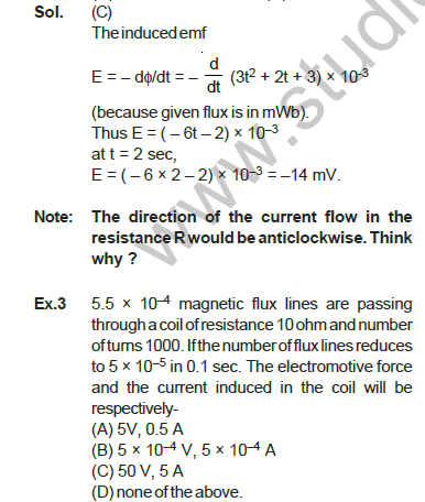
The magnetic flux passing perpendicular to the plane of the coil and directed into the paper is varying according to the relation \( \phi=3t^2+2t+3 \), where \(\phi\) is in milliwebers and \(t\) is in seconds. Then the magnitude of emf induced in the loop when \(t=2\) second is
- 31 mV
- 19 mV
- 14 mV
- 6 mV
Answer: (C)
The induced emf is \( E=-\dfrac{d\phi}{dt}=-\dfrac{d}{dt}(3t^2+2t+3)\times10^{-3}=-(6t+2)\times10^{-3} \) V (because the flux is in mWb). At \(t=2\) s, \( E=-(6\times2+2)\times10^{-3}=-14 \) mV.
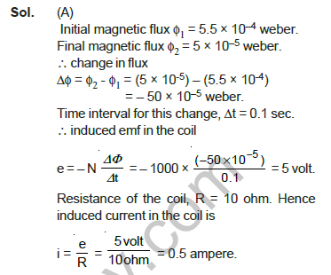
Note: the direction of the current flow in the resistance R would be anticlockwise. Think why?\(5.5\times10^{-4}\) magnetic flux lines (webers) are passing through a coil of resistance 10 ohm and number of turns 1000. If the flux reduces to \(5\times10^{-5}\) in 0.1 sec, the electromotive force and the current induced in the coil will be respectively
- 5 V, 0.5 A
- \(5\times10^{-4}\) V, \(5\times10^{-4}\) A
- 50 V, 5 A
- none of the above.
Answer: (A)
Initial flux \(\phi_1=5.5\times10^{-4}\) Wb; final flux \(\phi_2=5\times10^{-5}\) Wb. Change in flux \( \Delta\phi=\phi_2-\phi_1=-50\times10^{-5} \) Wb in \(\Delta t=0.1\) s.
\[ e=-N\frac{\Delta\Phi}{\Delta t}=-1000\times\frac{(-50\times10^{-5})}{0.1}=5\ \text{V} \]
With \(R=10\ \Omega\), the induced current is \( i=\dfrac eR=\dfrac{5}{10}=0.5 \) A.
A gramophone disc of brass of diameter 30 cm rotates horizontally at the rate of \(100/3\) revolutions per minute. If the vertical component of the earth's magnetic field be 0.01 weber/m², then the emf induced between the centre and the rim of the disc will be
- \(7.065\times10^{-4}\) V
- \(3.9\times10^{-4}\) V
- \(2.32\times10^{-4}\) V
- none of the above.
Answer: (B)
The flux through the disc is \( \phi=BA=0.01\times3.14\times(15\times10^{-2})^2=7.065\times10^{-4} \) Wb. The line joining the centre and the rim cuts this flux in one round, so the rate of cutting flux (the induced emf) is
\[ \text{flux}\times\text{revolutions per second}=7.065\times10^{-4}\times\frac{100}{60\times3}=3.9\times10^{-4}\ \text{V} \]
A closed coil consists of 500 turns on a rectangular frame of area 4.0 cm² and has a resistance of 50 ohm. The coil is kept with its plane perpendicular to a uniform magnetic field of 0.2 weber/m². The amount of charge flowing through the coil if it is turned over (rotated through 180°) will be

- \(1.6\times10^{-19}\) C
- \(1.6\times10^{-9}\) C
- \(1.6\times10^{-3}\) C
- \(1.6\times10^{-2}\) C
Answer: (C)
The flux through each turn is \(\phi_1=BA\); after rotating through 180° it is \(\phi_2=-BA\) (the sign changes because the flux lines now enter through the other face). So \( \Delta\phi=-2BA \), and the emf is \( e=-N\dfrac{\Delta\Phi}{\Delta t}=\dfrac{2NBA}{\Delta t} \). The current is \( i=\dfrac eR=\dfrac1R\dfrac{2NBA}{\Delta t} \) and it flows only for the time \(\Delta t\), so the charge passed is
\[ q=i\,\Delta t=\frac{2NBA}{R}=\frac{2\times500\times0.2\times4.0\times10^{-4}}{50}=1.6\times10^{-3}\ \text{C} \]
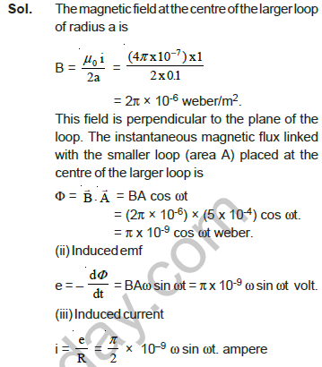
Note: rotating the coil slowly or fast has no effect on the charge that flows. The charge depends on the total change in magnetic flux, not on the rate of change of magnetic flux.A very small circular loop of area \(5\times10^{-4}\) m², resistance 2 ohm and negligible inductance is initially coplanar and concentric with a much larger fixed circular loop of radius 0.1 m. A constant current of 1 ampere is passed in the bigger loop and the smaller loop is rotated with angular velocity \(\omega\) rad/sec about a diameter. Calculate (i) the flux linked with the smaller loop, (ii) induced emf, and (iii) induced current in the smaller loop, as a function of time (\(\mu_0=4\pi\times10^{-7}\) V-s/A-m).
Answer: (i) \( \pi\times10^{-9}\cos\omega t \) Wb; (ii) \( \pi\times10^{-9}\,\omega\sin\omega t \) V; (iii) \( \dfrac{\pi}{2}\times10^{-9}\,\omega\sin\omega t \) A
The magnetic field at the centre of the larger loop of radius \(a\) is \( B=\dfrac{\mu_0 i}{2a}=\dfrac{(4\pi\times10^{-7})\times1}{2\times0.1}=2\pi\times10^{-6}\ \text{Wb/m}^2 \), perpendicular to the plane of the loop.
(i) The instantaneous flux linked with the smaller loop (area \(A\)) is \( \Phi=\vec B\cdot\vec A=BA\cos\omega t=(2\pi\times10^{-6})(5\times10^{-4})\cos\omega t=\pi\times10^{-9}\cos\omega t \) Wb.
(ii) Induced emf: \( e=-\dfrac{d\Phi}{dt}=BA\omega\sin\omega t=\pi\times10^{-9}\,\omega\sin\omega t \) V.
(iii) Induced current: \( i=\dfrac eR=\dfrac{\pi}{2}\times10^{-9}\,\omega\sin\omega t \) A.
A copper disc of radius 0.1 m rotates about its centre with 10 revolutions per second in a uniform magnetic field of 0.1 tesla. The emf induced across the radius of the disc is
- \(\pi/10\) V
- \(2\pi/10\) V
- \(10\pi\) mV
- \(20\pi\) mV
Answer: (C)
The induced emf between the centre and the rim is \[ E=\tfrac12B\omega R^2=\tfrac12\times0.1\times2\pi\times10\times(0.1)^2=10\pi\times10^{-3}\ \text{V} \]
Two rail tracks, insulated from each other and the ground, are connected to a millivoltmeter. What is the reading of the millivoltmeter when a train passes at a speed of 180 km/hr along the track, given that the horizontal component of earth's magnetic field is \(0.2\times10^{-4}\) Wb/m² and the rails are separated by 1 metre.
- 1 mV
- 10 mV
- 100 mV
- 1 V
Answer: (A)
The induced emf is \( E=Blv=0.2\times10^{-4}\times1\times\dfrac{180\times1000}{3600}=1\times10^{-3} \) V \(=1\) mV.
The annular disc of copper, with inner radius \(a\) and outer radius \(b\) is rotating with a uniform angular speed \(\omega\), in a region where a uniform magnetic field \(B\) along the axis of rotation exists. Then, the emf induced between the inner side and the outer rim of the disc is
- Zero
- \(\tfrac12B\omega a^2\)
- \(\tfrac12B\omega b^2\)
- \(\tfrac12B\omega(b^2-a^2)\)
Answer: (D)
Consider a thin strip of the disc. The linear speed of a small element \(dr\) at a distance \(r\) from the centre is \(\omega r\), so the emf across it is \( de=B\,dr\,v=B\omega r\,dr \). The emf across the inner and outer sides of the disc is
\[ e=\int_a^bB\omega r\,dr=\tfrac12B\omega(b^2-a^2) \]
A coil with 200 turns and area of 70 cm² is placed in a uniform magnetic field of strength 0.3 tesla pointing normal to the plane of the coil. If the coil turns through 180° in 0.1 sec, then the value of induced emf is
- 4.2 V
- 8.4 V
- 42 V
- 84 V
Answer: (B)
The change in flux is \(2BAN\), so \[ e=\frac{2BAN}{0.1}=\frac{2\times0.3\times200\times70\times10^{-4}}{0.1}=8.4\ \text{V} \]
A conducting wire in the shape of Y, with each side of length \(l\), is moving in a uniform magnetic field \(B\), with a uniform speed \(v\) as shown in the figure. The induced emf at the two ends X and Y of the wire will be
- Zero
- \(2Blv\)
- \(2Blv\sin(\theta/2)\)
- \(2Blv\cos(\theta/2)\)
Answer: (C)
The induced emf is \( e=-(\vec v\times\vec B)\cdot\vec l \). For the part PX, \(\vec v\perp\vec B\), and the angle between \( \vec v\times\vec B \) and the wire is \((90^\circ-\theta/2)\). Thus \( e_P-e_X=vBl\cos(90^\circ-\theta/2)=vBl\sin(\theta/2) \). Similarly \( e_Y-e_P=vBl\sin(\theta/2) \). Therefore the induced emf between X and Y is \( e_{YX}=2Bvl\sin(\theta/2) \).
Note: the induced emf between points P and Q is zero because \(\vec l\) is parallel to \(\vec v\). The induced emf between Q and X is \( Bvl\sin(\theta/2) \). The end Y is positive while X is negative. If the movement of the wire segment was upwards or downwards in the figure, then \( e_{XY}=0 \).In the figure, CODF is a semicircular loop of a conducting wire of resistance \(R\) and radius \(r\). It is placed in a uniform magnetic field \(B\), which is directed into the page (perpendicular to the plane of the loop). The loop is rotated with a constant angular speed \(\omega\) about an axis passing through the centre O, and perpendicular to the page. Then the induced current in the wire loop is
- Zero
- \( B r^2\omega/R \)
- \( B r^2\omega/2R \)
- \( B\pi r^2\omega/R \)
Answer: (C)
The area swept by the radius OC in one half circle is \( \pi r^2/2 \). The flux change in time \(T/2\) is thus \( \pi r^2B/2 \), so the induced emf is \( e=\dfrac{\pi r^2B}{T}=\dfrac{B\omega r^2}{2} \) (using \( T=2\pi/\omega \)). The induced current is then \( I=\dfrac eR=\dfrac{B\omega r^2}{2R} \).
A 10-metre wire is kept in the east-west direction. It is falling down with a speed of 5.0 m/s, perpendicular to the horizontal component of earth's magnetic field of \(0.30\times10^{-4}\) weber/m². The momentary potential difference induced between the ends of the wire will be
- 0.0015 V
- 0.015 V
- 0.15 V
- 1.5 V
Answer: (A)
If a wire of length \(l\) metre moves perpendicular to a magnetic field of \(B\) weber/m² with a velocity \(v\) m/s, the emf induced in the wire is \(V=Bvl\) volt. Here \(B=0.30\times10^{-4}\), \(v=5.0\) and \(l=10\):
\[ V=0.30\times10^{-4}\times5.0\times10=0.0015\ \text{V}=1.5\ \text{mV} \]
Note: by Fleming's left-hand rule, the magnetic force on a positive charge in the wire acts towards the east. Hence the force on the free electrons acts towards the west and they move to the western end of the wire. Hence the eastern end of the wire is at the higher (positive) potential.A metallic square wire-loop of side 10 cm and resistance 1 ohm is moved with a constant velocity \(v_0\) in a uniform magnetic field of induction \(B=2\) weber/m² as shown in the figure. The magnetic field lines are perpendicular to the plane of the loop (directed into the paper). The loop is connected to a network of resistors each of value 5 ohm. The resistance of the lead wires OS and PQ are negligible. What should be the speed of the loop so as to have a steady current of 1 milliampere in it? Give the direction of current in the loop.
Answer: \( v=3\times10^{-2} \) m/s; the current in the loop is clockwise.
The mesh of resistances OCSA is a balanced Wheatstone bridge, so the resistance CA is ineffective. Let the equivalent resistance of the bridge be \(R'\). Then \( \dfrac1{R'}=\dfrac1{10}+\dfrac1{10}=\dfrac15 \), or \(R'=5\ \Omega\). Total resistance of the circuit \(R=5+1=6\ \Omega\).
The emf induced in the loop is \(e=Bvl\), so the current in the loop is \( i=\dfrac eR=\dfrac{Bvl}{R} \), and the speed of the loop is \( v=\dfrac{iR}{Bl} \). For \(i=1\) mA \(=1\times10^{-3}\) A,
\[ v=\frac{(1\times10^{-3})\times6}{2\times0.1}=3\times10^{-2}\ \text{m/s} \]
According to Fleming's right-hand rule the current in the loop will be clockwise.
The current flowing in a coil whose coefficient of self-induction is 0.4 mH changes by 250 mA in 0.1 sec. The electromotive force (e.m.f.) induced in the coil will be
- 100 mV
- 30 mV
- 0.01 mV
- 1 mV
Answer: (D)
\( e=-L\dfrac{\Delta i}{\Delta t} \) with \(L=0.4\) mH \(=0.4\times10^{-3}\) H and \(\Delta i=0.250\) A:
\[ e=-(0.4\times10^{-3})\frac{0.250}{0.1}=-1\times10^{-3}\ \text{V} \]
so the magnitude is 1 mV. The minus sign indicates that the direction of the induced e.m.f. is such as to oppose the change in current.
In the circuit, \(E=10\) volt, \(R_1=5.0\) ohm, \(R_2=10\) ohm and \(L=5.0\) henry. Calculate the currents \(i_1\), \(i_2\) and \(i\) (i) just when the switch S is pressed, (ii) after sufficient time the switch S has been pressed.
Answer: (i) \(i=i_1=2.0\) A, \(i_2=0\); (ii) \(i=3.0\) A, \(i_1=2.0\) A, \(i_2=1.0\) A
(i) Immediately after pressing the switch S, the current in the coil L, due to its self-induction, will be zero, that is \(i_2=0\). The current will only be found in the resistance \(R_1\) and this will be the total current in the circuit: \( i=i_1=\dfrac E{R_1}=\dfrac{10}{5.0}=2.0 \) A.
(ii) After sufficient time the current is established in L and in \(R_2\) also. Because \(R_1\) and \(R_2\) are in parallel, the equivalent resistance is \( R=\dfrac{R_1R_2}{R_1+R_2}=\dfrac{5.0\times10}{5.0+10}=\dfrac{10}3\ \Omega \). So the total current is \( i=\dfrac ER=\dfrac{10}{10/3}=3.0 \) A.
Since the internal resistance of the cell is negligible, the potential difference across \(R_1\) is \(V=10\) V, so the current in \(R_1\) is \( i_1=\dfrac V{R_1}=\dfrac{10}{5.0}=2.0 \) A. The current in \(R_2\) is \( i_2=i-i_1=3.0-2.0=1.0 \) A.
Two inductors \(L_1\) and \(L_2\) are at a sufficient distance apart. Find out the equivalent inductance when they are connected (i) in series (ii) in parallel.
Answer: (i) \( L=L_1+L_2 \); (ii) \( L=\dfrac{L_1L_2}{L_1+L_2} \)
(i) In series the same current \(i\) flows in both the inductors and the total magnetic flux linked with them is the sum of the fluxes linked with them individually, that is \( \Phi=L_1i+L_2i \). If the equivalent inductance is \(L\), then \(\Phi=Li\), so \( Li=L_1i+L_2i \), or \( L=L_1+L_2 \).
(ii) In parallel, let the currents in the two coils be \(i_1\) and \(i_2\). Then the total current is \( i=i_1+i_2 \), so \( \dfrac{di}{dt}=\dfrac{di_1}{dt}+\dfrac{di_2}{dt} \). In parallel, the induced e.m.f. across each coil is the same, so \( e=-L_1\dfrac{di_1}{dt}=-L_2\dfrac{di_2}{dt} \). If the equivalent inductance is \(L\), then \( e=-L\dfrac{di}{dt} \). Therefore
\[ \frac eL=-\frac{di}{dt}=-\left(\frac{di_1}{dt}+\frac{di_2}{dt}\right)=\frac e{L_1}+\frac e{L_2}\ \Rightarrow\ \frac1L=\frac1{L_1}+\frac1{L_2}\ \Rightarrow\ L=\frac{L_1L_2}{L_1+L_2} \]
A small coil of \(N_1\) turns, length \(l_1\), is tightly wound over the centre of a long solenoid of length \(l_2\), area of cross-section \(A\) and number of turns \(N_2\). If a current \(I\) flows in the small coil, then what is the flux through the long solenoid?
- Zero
- \( \dfrac{\mu_0N_1^2AI}{l_1} \)
- infinite
- \( \dfrac{\mu_0N_1N_2AI}{l_2} \)
Answer: (D)
If we try to find the field of the small coil and then calculate the flux through the long solenoid, the problem becomes very difficult. So we use the fact about mutual inductance: \( M_{21}=M_{12} \), i.e. \( \dfrac{\phi_2}{I_1}=\dfrac{\phi_1}{I_2} \).
Thus if a current \(I\) flows in the long solenoid, the flux \(\phi\) through the small coil is the same as the flux \(\phi_2\) obtained when current \(I\) flows through the small coil. Therefore \( \phi_2=\phi_1=(\text{field at small coil})\times(\text{area})\times(\text{turns}) \):
\[ \phi=\left(\mu_0\frac{N_2}{l_2}I\right)(AN_1)=\frac{\mu_0N_1N_2AI}{l_2} \]
If the current in the primary coil is reduced from 3.0 ampere to zero in 0.001 second, the induced e.m.f. in the secondary coil is 1500 volt. The mutual inductance of the two coils will be
- 0.5 H
- 0.05 H
- 0.005 H
- 0.0005 H
Answer: (A)
The induced e.m.f. is \( e=-M\dfrac{\Delta i}{\Delta t} \), or \( M=-\dfrac{e}{\Delta i/\Delta t} \). Here \(e=1500\) V:
\[ M=-\frac{1500}{(0-3.0)/0.001}=\frac{1500\times0.001}{3.0}=0.5\ \text{H} \]
A 50 Hz a.c. current of crest value 1 A flows through the primary of a transformer. If the mutual inductance between the primary and secondary be 1.5 H, the crest voltage induced in the secondary is
- 75 V
- 150 V
- 225 V
- 300 V
Answer: (D)
The crest value is attained in \(T/4\) time, where \(T\) is the time period of the a.c. Thus \(dI=1\) A in \(dt=T/4\) s. Since \( T=\dfrac1{50} \) s, \( dt=\dfrac1{200} \) s. The induced emf is
\[ |E_2|=M\frac{dI_1}{dt}=1.5\times\frac{1}{(1/200)}=1.5\times200=300\ \text{V} \]
(A) 7.065 × 10⁻⁴ V (B) 3.9 × 10⁻⁴ V (C) 2.32 × 10⁻⁴ V (D) none of the above.
Sol. (B) Magnetic flux passing through the disc is φ = BA = 0.01 weber/ meter2 × 3.14 × (15 × 10–2 meter)2 = 7.065 × 10⁻⁴ weber.
Please click on below link to download pdf file for CBSE Class 12 Physics Electromagnetic Induction Solved Examples.
Free study material for Physics
CBSE Class 12 Physics Study Material: Chapter 06 Electromagnetic Induction
Core Study Kit: Class 12 Physics Chapter 06 Electromagnetic Induction
Review targeted study resources for Chapter 06 Electromagnetic Induction tailored for Class 12 learners. Utilizing these structured notes and quick-revision tools ensures complete alignment with current CBSE evaluation standards.
NCERT-Aligned Solutions for Chapter 06 Electromagnetic Induction
Built using official NCERT guidelines for Class 12 Physics, these materials provide reliable academic support. Integrating past examination questions and step-by-step solutions helps students understand official CBSE grading criteria.
Next Steps in Your Exam Preparation
For peak performance in upcoming evaluations, integrate official Physics sample papers directly into your study schedule. Follow up your revision by attempting online MCQ tests for Chapter 06 Electromagnetic Induction to refine calculation speed and precision.
FAQs
Our advanced study package for Chapter 06 Electromagnetic Induction includes detailed concepts, diagrams, Mind Maps, and explanation of complex topics to ensure Class 12 students learn as per syllabus for 2026 exams.
The Mind Maps provided for Chapter 06 Electromagnetic Induction act as visual anchors which will help faster recall during high-pressure exams.
Yes, teachers use our Class 12 Physics resources for lesson planning as they are in simple language and have lot of solved examples.
Yes, You can download the complete, mobile-friendly PDF of the Physics Chapter 06 Electromagnetic Induction advanced resources for free.
Yes, our subject matter experts have updated the Chapter 06 Electromagnetic Induction material to align with the rationalized NCERT textbooks and have removed deleted topics and added new competency-based questions.