

Class 12 Physics Study Guide: CBSE Class 12 Physics Electromagnetic Induction And Alternating Currents chapter notes and important questions
Access comprehensive study materials and useful resources for Chapter 06 Electromagnetic Induction using the CBSE Class 12 Physics Electromagnetic Induction And Alternating Currents chapter notes and important questions. Designed to align with the 2026-27 CBSE academic guidelines, these advanced resources help Class 12 Physics students reinforce core concepts beyond standard textbooks.
Download Chapter 06 Electromagnetic Induction Study Material PDF
Access the complete useful resource PDF for Class 12 Physics below. Regular practice with these targeted academic notes builds familiarity with complex topics and helps secure higher marks in final school evaluations.
This CBSE Class 12 Physics chapter 4 covers Electromagnetic Induction and Alternating Currents. The gist gives the key laws and formulas: magnetic flux, Faraday's and Lenz's laws, motional emf, eddy currents, self and mutual inductance, AC generator, rms values, LCR circuits, resonance, transformers and free oscillations. The important questions that follow include the answers and Teacher's Notes for board exam practice.
CHAPTER 4: ELECTROMAGNETIC INDUCTION AND ALTERNATING CURRENTS
GIST
1. The phenomenon in which an electric current is generated by a varying magnetic field is called electromagnetic induction.
2. Magnetic flux through a surface of area A placed in a uniform magnetic field B is ΦB = B·A = BA cos θ, where θ is the angle between B and the area vector A.
3. Magnetic flux is a scalar quantity. Its S.I. unit is weber (Wb). Its dimensional formula is [ML²T⁻²A⁻¹].
4. Faraday's law of induction states that the magnitude of the induced emf in a circuit is equal to the time rate of change of magnetic flux through the circuit: ε = -dΦ/dt.
5. According to Lenz's law, the direction of the induced current, or the polarity of the induced emf, is such that it opposes the change in magnetic flux that produces it. The negative sign in Faraday's law shows this.
6. Lenz's law obeys the principle of conservation of energy.
7. An induced emf can be produced by changing (i) the magnitude of B, (ii) the area A, or (iii) the angle θ between B and the normal to the area A.
8. When a metal rod of length l is placed normal to a uniform magnetic field B and moved with velocity v perpendicular to the field, the induced emf is called motional emf, given by ε = Blv.
9. Changing magnetic fields can set up current loops in nearby metal bodies (any conductor). Such currents are called eddy currents. They dissipate energy as heat, which can be minimised by laminating the conductor.
10. Inductance is the ratio of flux linkage to current.
11. When the current in a coil changes, it induces a back emf in the same coil. This is called self induction, and the self induced emf is ε = -L dI/dt, where L is the self inductance of the coil. Self inductance is a measure of the inertia of the coil against change of current through it. Its S.I. unit is henry (H).
12. A changing current in one coil can induce an emf in a nearby coil. This is mutual induction, and the mutual inductance of coil 1 with respect to coil 2 (M12) is due to the change of current in coil 2. M12 = M21.
13. The self inductance of a long solenoid is L = μ0n²Al, where A is the cross-sectional area of the solenoid, l is its length and n is the number of turns per unit length.
14. The mutual inductance of two co-axial solenoids is M12 = M21 = μ0n1n2Al, where n1 and n2 are the numbers of turns per unit length of coils 1 and 2, A is the area of cross-section and l is the length of the solenoids.
15. Energy stored in an inductor in the form of a magnetic field is UB = (1/2) L I²max. The magnetic energy density is uB = B²/(2μ0).
16. In an AC generator, mechanical energy is converted into electrical energy by electromagnetic induction. Rotation of a rectangular coil in a magnetic field changes the flux, Φ = NBA cos ωt. The induced emf is ε = -dΦ/dt = NBAω sin ωt, so ε = ε0 sin ωt. The induced current is I = ε/R = I0 sin ωt.
17. An alternating voltage ε = ε0 sin ωt applied to a resistor R drives a current I = I0 sin ωt, where I0 = ε0/R. ε0 and I0 are the peak values, also written Vm and Im.
18. The root mean square (rms) value of an AC is the value of steady current which would generate the same heat in a given resistance in a given time as the AC does. Irms = I0/√2 = 0.707 I0, and similarly Vrms = V0/√2 = 0.707 V0. For an AC source ε = εm sin ωt applied to a resistor, current and voltage are in phase.
19. In an AC circuit with pure inductance, current lags behind the emf by a phase angle of 90°. \( \varepsilon = \varepsilon_m \sin \omega t \) and \( i = i_m \sin(\omega t - \pi/2) \); \( I_m = \varepsilon_m / X_L \), where \( X_L = \omega L \) is called inductive reactance.
20. In an AC circuit with pure capacitance, current leads the emf by a phase angle of 90°. \( \varepsilon = \varepsilon_m \sin \omega t \) and \( I = I_m \sin(\omega t + \pi/2) \), where \( I_m = \varepsilon_m / X_C \) and \( X_C = 1/\omega C \) is called capacitive reactance.
21. In an AC circuit containing R, L and C, the total effective opposition is called impedance (Z). \( Z = \varepsilon_m / I_m = \sqrt{R^2 + (X_C - X_L)^2} \). tan φ = (XL - XC)/R, where φ is the phase difference between current and voltage. With \( I = I_m \sin(\omega t + \phi) \), the PDF gives \( \tan\phi = \dfrac{X_C - X_L}{R} \). \( \varepsilon = \varepsilon_m \sin \omega t,\; I = I_m \sin(\omega t + \phi) \).
22. The average power loss over a complete cycle in an LCR circuit is P = εrms Irms cos φ.
i) In a purely resistive circuit φ = 0, so P = Vrms Irms.
ii) In a purely inductive circuit φ = π/2, so P = 0.
iii) In a purely capacitive circuit φ = π/2, so P = 0.
23. In an LCR circuit, maximum current flows when XC = XL, so Z = R. The resonant frequency is ωr = 1/√(LC), and νr = 1/(2π√(LC)).
24. The Q factor of a series resonant circuit is the ratio of the voltage developed across the inductance or capacitance at resonance to the applied voltage across R. \( Q = \dfrac{\omega_r L}{R} \) or \( \dfrac{1}{\omega_r C R} \); also \( Q = \dfrac{\omega_r}{2\Delta\omega} \), where \( 2\Delta\omega \) is the bandwidth.
25. For a transformer, \( \dfrac{E_s}{E_p} = \dfrac{N_s}{N_p} = \dfrac{i_p}{i_s} = K \). For an ideal transformer, EP IP = ES IS. If NS is greater than NP, then ES is greater than EP and IS is less than IP, which is a step up transformer. If NP is greater than NS, then EP is greater than ES and IP is less than IS, which is a step down transformer.
26. A circuit containing an inductor L and a charged capacitor C, with no AC source and no resistor, shows free oscillations of energy between the capacitor and the inductor. The charge q satisfies d²q/dt² + (1/LC) q = 0.
IMPORTANT QUESTIONS
1. Two concentric circular coils are perpendicular to each other. Coil I carries a current i. If this current is changed, will this induce a current in the coil II?
Answer: No. The field due to coil I is parallel to the plane of coil II, so the flux through coil II does not change.
Teacher's Note:
a) Flux is the component of the field normal to the area, and here that component is zero.
b) Induced current needs a change in flux, not just a change in current.
2. A closed loop of wire is being moved with constant velocity without changing its orientation inside a uniform magnetic field. Will this induce a current in the loop?
Answer: No. The flux through the loop does not change, because the field is uniform and the orientation and area inside the field remain the same.
Teacher's Note:
a) Motion alone does not induce an emf in a uniform field.
b) An emf appears only if the loop enters or leaves a region of changing field.
3. A cylindrical bar magnet is kept along the axis of a circular coil and near it as shown in the fig. Will there be any induced current at the terminals of the coil when the magnet is rotated (a) about its own axis (b) about an axis perpendicular to the length of the magnet?
Answer:
(a) No emf is induced when the magnet is rotated about its own axis, because there is no change in flux through the coil.
(b) Yes, an emf is induced when the magnet is rotated about a perpendicular axis, because the flux through the coil changes continuously.
Teacher's Note:
a) Rotation about the magnet's own axis keeps the field pattern unchanged at the coil.
b) Rotation about a perpendicular axis changes the orientation of the magnet's field relative to the coil.
4. A conducting wire is kept along the N to S direction and is allowed to fall freely. Will an emf be induced in the wire?
Answer: No. The velocity of the wire is vertical and the horizontal component of the earth's field is along N to S, which is parallel to the wire. So the force on the free electrons is perpendicular to the wire, and no emf is developed along it.
Teacher's Note:
a) Motional emf needs the velocity, the field and the wire length to be mutually perpendicular.
b) The vertical component of the earth's field does not give an emf in a vertically falling wire.
5. A conducting wire is kept along the E to W direction and is allowed to fall freely. Will an emf be induced in the wire?
Answer: Yes. The wire moves vertically across the horizontal component of the earth's field, which is perpendicular to the wire. So an emf is induced across its ends.
Teacher's Note:
a) The emf is ε = BH l v, where BH is the horizontal component.
b) Compare this with question 4, where the wire lies along the field direction.
6. A vertical magnetic pole falls down through the plane of magnetic meridian. Will any emf be induced between its ends?
Answer: No. The pole intercepts neither the vertical component BV nor the horizontal component BH of the earth's field in a way that gives an emf between its ends.
Teacher's Note:
a) A pole falling in the plane of the magnetic meridian moves parallel to the horizontal field.
b) Induced emf needs a component of velocity perpendicular to the field and to the length.
7. A wheel with a certain number of spokes is rotated in a plane normal to earth's magnetic field so that an emf is induced between the axle and rim of the wheel. Keeping all other things same, number of spokes is changed. How is the emf affected? (Hint: Number of spokes does not affect the net emf)
Answer: The emf is not affected. The net emf depends only on the area swept by the spokes per revolution, and the number of spokes does not change this.
Teacher's Note:
a) The emf is ε = (1/2) B ω r², which has no term for the number of spokes.
b) Each spoke carries a share of the emf, and these shares add in parallel, so the net emf stays the same.
8. What are eddy currents?
Answer: Eddy currents are induced circulating currents set up in bulk conductors when they are placed in a changing magnetic flux.
Teacher's Note:
a) Eddy currents produce heat, which is why they are a source of energy loss.
b) Laminating the core reduces these currents.
9. Find the RMS value of A.C shown in the figure.
Answer: From the figure the current is ±2 A for only part of the period, with the mean of I² equal to 2 A², so Irms = √2 A. (A wave that is ±2 A throughout would give Irms = 2 A, since I² = 4 A² at every instant.)
Teacher's Note:
a) The rms value of a current that is always ±I0 is equal to I0.
b) The key value √2 A applies because the current is 2 A for only half of the cycle in the figure.
10. The instantaneous value of emf is given by ε = 300 sin 314t. What is the rms value of emf?
Answer: ε0 = 300 V, so εrms = 300/√2 = 212.1 V.
Teacher's Note:
a) The coefficient of sin in the equation is the peak value.
b) The value 314 is ω, which gives a frequency of 50 Hz.
11. Why is a 220 V AC considered to be more dangerous than 220 V DC?
Answer: The peak value of 220 V AC is about 311 V, which is more than the rms value of 220 V. The peak voltage is what causes the greater risk of electric shock.
Teacher's Note:
a) The rms value of 220 V AC is the same heating effect as 220 V DC.
b) Shock damage depends on the peak voltage and the current it drives.
12. AC current flows through a circuit consisting of different elements connected in series. (i) Is the applied instantaneous voltages equal to the algebraic sum of instantaneous voltages across the series elements of the circuit? (ii) Is it true for rms voltages?
Answer:
(i) Yes, the instantaneous voltages add algebraically.
(ii) No, the rms voltages do not add algebraically, because the voltages across the elements have different phases.
Teacher's Note:
a) Phasors must be added for rms voltages across L, C and R.
b) This is why the rms voltage across an LCR circuit can be larger than the source voltage.
13. A capacitor blocks DC. Why?
Answer: The reactance of a capacitor is XC = 1/(2πνC). For DC, ν = 0, so XC is infinite and no steady current can flow.
Teacher's Note:
a) The higher the frequency, the lower the reactance of a capacitor.
b) A capacitor allows AC to pass because it keeps charging and discharging.
14. What is the phase relationship between emf across L and C in a series LCR circuit connected to an AC source?
Answer: The voltages across L and C are 180° out of phase with each other.
Teacher's Note:
a) VL leads the current by 90°, and VC lags the current by 90°.
b) So their phase difference is 180°, and they subtract in a series circuit.
15. Two alternating currents are given by I1 = I0 sin ωt and I2 = I0 sin(ωt + π/3). Will the rms value of I1 and I2 be equal or different?
Answer: The rms values will be equal, because both have the same peak value I0. The phase difference does not change the rms value.
Teacher's Note:
a) Irms depends only on the peak value.
b) Phase only affects the timing of the current, not its heating effect averaged over a cycle.
16. Sketch a graph showing the variation of impedance of LCR circuit with the frequency of applied voltage.
[Figure: Graph of impedance Z on the vertical axis against frequency ν on the horizontal axis. The curve is U shaped, falling from a high value to a minimum at the resonant frequency νr, and then rising again.]
Answer: The impedance is high at low frequencies, falls to its minimum value R at the resonant frequency νr, and then rises again at high frequencies.
Teacher's Note:
a) At resonance, XL = XC, so Z = R.
b) The curve is symmetrical only on a logarithmic frequency scale.
17. What is meant by wattless current?
Answer: Wattless current is the component of AC that flows in a circuit without consuming any average power. It occurs when the phase difference between current and voltage is 90°, as in a pure inductor or capacitor.
Teacher's Note:
a) Wattless current is given by Irms sin φ, and the power factor is cos φ.
b) Circuits with a low power factor carry more wattless current.
18. Define Q factor in LCR series circuit.
Answer: The Q factor of a series LCR circuit is the ratio of the voltage developed across the inductance or capacitance at resonance to the applied voltage across R. It is given by Q = ωrL/R = (1/R)√(L/C).
Teacher's Note:
a) A high Q means a sharp resonance and a narrow bandwidth.
b) Q is a dimensionless quantity.
19. Why is choke coil preferred over resistor to reduce AC?
Answer: A choke coil reduces the AC current by its inductive reactance, and an ideal inductor dissipates no average power. A resistor reduces the current too, but it dissipates the electrical energy as heat.
Teacher's Note:
a) This is why choke coils are used with fluorescent tubes.
b) A choke works only with AC, since its reactance is zero for DC.
20. Why is the core of a transformer laminated?
Answer: The core is laminated to reduce eddy currents. Thin insulated laminations increase the resistance of the path of eddy currents, so energy losses as heat are reduced.
Teacher's Note:
a) Laminated iron cores are also used in motors and generators.
b) Eddy current loss appears as heat in the core.
21. Why can't a transformer be used to step up DC voltages?
Answer: A transformer works on the principle of mutual induction, which needs a changing flux. A DC current gives a steady flux, so no emf is induced in the secondary coil.
Teacher's Note:
a) A transformer needs an alternating current to change the flux continuously.
b) Using DC would also heat the primary coil with a large current.
22. Does current in AC circuit lag, lead or remain in phase with voltage of frequency ν applied to a series LCR circuit when (i) ν = νr (ii) ν < νr (iii) ν > νr, where νr is resonant frequency?
Answer:
(i) At ν = νr, the current is in phase with the voltage.
(ii) At ν < νr, the current leads the voltage, because the circuit is capacitive.
(iii) At ν > νr, the current lags the voltage, because the circuit is inductive.
Teacher's Note:
a) At low frequency, XC is large, so the circuit is capacitive.
b) At high frequency, XL is large, so the circuit is inductive.
23. If the speed of rotation of armature is increased twice how would it affect the (a) maximum emf produced (b) frequency of the emf? (ε = NBAω; ν = ω/2π)
Answer:
(a) The maximum emf is doubled, because ε0 = NBAω and ω doubles.
(b) The frequency is doubled, because ν = ω/2π.
Teacher's Note:
a) Both emf and frequency are directly proportional to the rotation speed.
b) The rms current in a resistor also doubles, since it depends on the emf.
24. Explain any two applications of eddy current.
Answer:
1. Electromagnetic braking in trains: eddy currents in a metal disc or rail oppose its motion, which slows the train without friction.
2. Induction furnace: strong eddy currents are produced in a metal charge placed in a changing magnetic field, which heats and melts it.
Teacher's Note:
a) Eddy currents also operate electric energy meters and metal detectors.
b) Electromagnetic braking has no wear and tear because there is no mechanical contact.
25. Two coils P and S are arranged as shown in the figure. (i) What will be the direction of induced current in S when the switch is closed? (ii) What will be the direction of induced current in S when the switch is opened?
[Figure: Coil P is a large circular loop with a battery and a switch in a circuit connected to it, and coil S is a smaller circle placed inside coil P, sharing the same centre.]
Answer:
(i) When the switch is closed, the current in P increases and the flux through S increases. The induced current in S is anticlockwise.
(ii) When the switch is opened, the current in P decreases and the flux through S decreases. The induced current in S is clockwise.
Teacher's Note:
a) Lenz's law says the induced current opposes the change in flux.
b) The direction in both cases is set by the direction of the battery current shown in the figure.
26. A conducting circular loop is placed in a uniform magnetic field B = 0.020 T with its plane perpendicular to the field. Somehow, the radius of the loop starts shrinking at a constant rate of 1 mm/s. Find the induced current in the loop at an instant when the radius is 2 cm.
Answer:
1. Flux Φ = πr²B, so ε = -dΦ/dt = -2πrB (dr/dt).
2. |ε| = 2π × 0.02 m × 0.020 T × 0.001 m/s = 2.5 × 10⁻⁶ V = 2.5 μV.
3. Induced current I = ε/R, where R is the resistance of the loop. Since R is not given, the emf of 2.5 μV is the answer.
Teacher's Note:
a) The printed key gives 25 μV, but the correct value from this data is 2.5 μV.
b) Divide 2.5 μV by the resistance of the loop to get the current.
27. A 12 V battery is connected to a 6 Ω; 10 H coil through a switch drives a constant current in the circuit. The switch is suddenly opened. Assuming that it took 1 ms to open the switch calculate the average emf induced across the coil.
Answer:
1. Steady current before opening: I1 = 12/6 = 2 A.
2. Current after opening: I2 = 0, so dI = -2 A.
3. Average emf: |ε| = L |dI/dt| = 10 × 2/(1 × 10-3) = 20000 V.
Teacher's Note:
a) This large emf is the reason switches of inductive circuits produce sparks.
b) A larger opening time would reduce the induced emf.
28. A coil of mean area 500 cm² having 1000 turns is held perpendicular to a uniform magnetic field of 0.4 G. The coil is turned through 180° in 1/10 seconds. Calculate the average induced emf.
Answer:
1. Area A = 500 cm² = 0.05 m². Field B = 0.4 G = 4 × 10⁻⁵ T.
2. Change in flux when turned through 180°: ΔΦ = 2NBA = 2 × 1000 × 4 × 10-5 × 0.05 = 4 × 10⁻³ Wb.
3. Average emf = ΔΦ/Δt = 4 × 10⁻³/(1/10) = 0.04 V.
Teacher's Note:
a) Turning through 180° reverses the flux, so the change is twice the flux.
b) Convert gauss to tesla by dividing by 104.
29. A conducting rod of length l with one end pivoted is rotated with a uniform angular speed ω in a vertical plane normal to uniform magnetic field B. Deduce an expression for emf induced in this rod.
Answer:
1. A small element dx at distance x from the pivot has speed v = ωx.
2. The emf across this element is dε = Bv dx = Bωx dx.
3. Integrating from 0 to l: ε = ∫0l Bωx dx = (1/2) Bωl².
Teacher's Note:
a) The emf is proportional to the square of the length of the rod.
b) The same result is given by the rate of sweeping the area: ε = (1/2) Bωl².
30. Two conducting circular loops of radii R1 and R2 are placed in the same plane with their centres coinciding. Find the mutual inductance between them assuming R2 << R1.
Answer: M = μ0πR2²/(2R1)
Teacher's Note:
a) The field at the centre of the large loop is μ0I/(2R1), which is nearly uniform over the small loop.
b) Flux through the small loop is that field times πR2², which gives M.
31. Prove that the total inductance of two coils connected in parallel is \(\frac{1}{L_T} = \frac{1}{L_1} + \frac{1}{L_2}\)
Answer:
1. For coils in parallel, the emf across each coil is the same, V = L1 dI1/dt = L2 dI2/dt.
2. The total current is I = I1 + I2, so dI/dt = V/L1 + V/L2.
3. Let LT be the total inductance, so V = LT dI/dt. Then 1/LT = 1/L1 + 1/L2.
Teacher's Note:
a) This result assumes no mutual inductance between the two coils.
b) The formula looks the same as for resistors in parallel.
32. Two circular loops are placed with their centres at fixed distance apart. How would you orient the loops to have (i) maximum (ii) minimum mutual inductance?
Answer:
(i) Maximum mutual inductance: the loops should be coaxial, with their planes parallel to each other.
(ii) Minimum mutual inductance: the loops should be placed with their planes perpendicular to each other, so that the flux from one loop does not pass through the other.
Teacher's Note:
a) Mutual inductance depends on how much of one loop's flux links the other.
b) Perpendicular planes give zero flux linkage in the ideal case.
33. A coil of wire of certain radius has 600 turns and inductance of 108 mH. What will be the inductance of another similar coil with 500 turns?
Answer:
1. Inductance is proportional to the square of the number of turns, L ∝ N².
2. L2 = 108 × (500/600)² = 108 × 0.694 = 75 mH.
Teacher's Note:
a) The coil geometry is the same, so only the turns change.
b) Doubling the turns would make the inductance four times larger.
34. Obtain the mutual inductance of a pair of coaxial circular coils kept separated by a distance as shown in fig.
[Figure: A large coil of radius R and a small coil of radius r placed coaxially with their centres a distance x apart on the same axis.]
Answer:
1. Field on the axis of the large coil at distance x: B = μ0IR²/(2(R² + x²)3/2).
2. Flux through the small coil, taking the field uniform over its area: Φ = Bπr².
3. So M = Φ/I = μ0πr²R²/(2(R² + x²)3/2).
Teacher's Note:
a) This assumes the small coil is much smaller than the large one, so the field is uniform over it.
b) At x = 0 the result reduces to μ0πr²/(2R), which matches question 30.
35. An alternating current is given by i = i1 cos ωt + i2 sin ωt. Find the rms current in the circuit.
Answer:
1. The mean square current over a cycle is I2rms = (i1² + i2²)/2, because the cross term averages to zero.
2. So Irms = √((i1² + i2²)/2).
Teacher's Note:
a) The sine and cosine terms are 90° out of phase, so their product averages to zero.
b) Each term contributes half its square to the mean square current.
36. An alternating current having a peak value of 14 A is used to heat a metal wire. What is the value of steady current which can produce the same heating effect as produced by AC? Why?
Answer: Irms = 14/√2 = 9.9 A, which is about 10 A. A steady current of this value produces the same heating effect, because the rms value is defined by equal heating in a given time.
Teacher's Note:
a) Heat depends on the square of the current, so the average of I² is what matters.
b) The rms value is the steady current that gives the same average heating.
37. If a constant current of 2.8 A exists in a resistor, what is the rms value of current? Why?
Answer: The rms value is 2.8 A, because a constant (DC) current has the same value at every instant, so its rms value equals its magnitude.
Teacher's Note:
a) rms is the same as the steady value for DC.
b) Peak and rms values differ only for alternating currents.
38. In an AC circuit there is no power consumption in an ideal inductor. Why?
Answer: In an ideal inductor, the current lags the voltage by 90°, so cos φ = 0 and P = Vrms Irms cos 90° = 0. The energy is stored in the magnetic field and returned to the circuit in each cycle.
Teacher's Note:
a) An ideal inductor has no resistance, so no energy is converted to heat.
b) Average power over a complete cycle is zero for the same reason.
39. An LCR series circuit is connected to an AC source. Which of its components dissipates power L or C or R? Justify your answer.
Answer: Only the resistor R dissipates power. The average power in L and C is zero, because the current is 90° out of phase with the voltage across each of them.
Teacher's Note:
a) Power dissipated in the circuit is Irms² R.
b) L and C store and return energy in each cycle.
40. An electric lamp connected in series with a capacitor and an AC source is glowing with certain brightness. How does the brightness of the lamp change on reducing the capacitance?
Answer: The brightness decreases. Reducing C increases XC, so the impedance Z increases and the current I decreases.
Teacher's Note:
a) XC = 1/(2πνC) is inversely proportional to C.
b) Lower current means less power in the lamp.
41. The power factor of an AC circuit is lagging by a factor 0.5. What does it mean?
Answer: The power factor cos φ = 0.5, so φ = 60°. This means the current lags behind the applied voltage by a phase angle of 60°.
Teacher's Note:
a) Power factor is the cosine of the phase angle between current and voltage.
b) A lagging power factor means the circuit is inductive.
42. The peak value of an AC is 5 A and its frequency is 60 Hz. Find its rms value. How long will the current take to reach the peak value starting from zero?
Answer:
1. Irms = 5/√2 = 3.5 A.
2. Time period T = 1/60 s. The current reaches its peak value from zero in T/4.
3. t = T/4 = 1/240 s, which is about 4.2 ms.
Teacher's Note:
a) A sine wave goes from zero to its peak in a quarter of its period.
b) The rms value is the peak divided by √2.
43. The voltage and current in a series AC circuit are given by V = V0 cos ωt and I = I0 sin ωt. What is the power dissipated in the circuit?
Answer: V = V0 sin(ωt + π/2), so the voltage leads the current by π/2. The circuit is inductive, and the power dissipated is P = 0.
Teacher's Note:
a) A phase difference of 90° gives cos 90° = 0.
b) Voltage leading current by 90° means the net reactance is inductive.
44. When an AC source is connected to a capacitor with a dielectric slab between its plates, will the rms current increase or decrease or remain constant?
Answer: The rms current increases. The dielectric increases the capacitance, which decreases the reactance XC = 1/(2πνC), so the current increases.
Teacher's Note:
a) A dielectric slab multiplies the capacitance by its dielectric constant k.
b) This is the reverse of question 40.
45. Can peak voltage across an inductor be greater than the peak voltage supplied to an LCR?
Answer: Yes. When a circuit containing an inductor is suddenly broken, a large back emf is set up across the inductor, which can exceed the supply voltage.
Teacher's Note:
a) This is the principle behind the spark in an induction coil.
b) Switches in inductive circuits should be designed for such voltages.
46. Write any two differences between impedance and reactance.
Answer:
1. Impedance is the total opposition offered by a circuit containing R, L and C, given by Z = √(R² + (XL - XC)²). Reactance is the opposition offered only by an inductor or a capacitor (XL or XC).
2. Impedance includes the resistance of the circuit, while reactance does not. In a purely resistive circuit impedance equals R, and there is no reactance.
Teacher's Note:
a) Both are measured in ohms.
b) Impedance is the vector sum of resistance and net reactance.
47. A 100 Ω resistor is connected to 220 V, 50 cycles per second. What is (i) peak potential difference (ii) average potential difference and (iii) rms current?
Answer:
1. Peak potential difference: V0 = 220√2 = 311.1 V.
2. Average potential difference over a half cycle: Vavg = 2V0/π = 198 V. (Over a complete cycle the average is zero.)
3. rms current: Irms = 220/100 = 2.2 A.
Teacher's Note:
a) The average value is always taken over a half cycle for AC voltage.
b) The rms value is the one shown on the supply and used in power calculations.
48. If resistance R in circuit 'a' be decreased, what will be the direction of induced current in the circuit 'b'?
[Figure: Circuit a is a rectangular loop with a battery, a switch and a variable resistor R on its left side. Circuit b is a second rectangular loop placed beside circuit a on its right side.]
Answer: The induced current in circuit b is anticlockwise.
Teacher's Note:
a) Decreasing R increases the current in circuit a, so the flux through circuit b increases.
b) By Lenz's law, the current induced in b opposes this increase, and this gives an anticlockwise current in b.
49. For circuits for transporting electric power, a low power factor implies large power loss in transmission line. Why?
Answer: For a given power P at voltage V, the current is I = P/(V cos φ). A low power factor makes the current large, and the power loss I²R in the line is large.
Teacher's Note:
a) Power companies try to keep the power factor close to one.
b) Capacitors are added to improve a lagging power factor.
50. An inductor of inductance 100 mH is connected in series with a resistance, a variable capacitance and an AC source of frequency 2 kHz. What should be the value of the capacitance so that maximum current may be drawn into the circuit?
Answer:
1. For maximum current, resonance: XC = XL, so 1/(ωC) = ωL.
2. C = 1/(ω²L), with ω = 2π × 2000 = 1.257 × 10⁴ rad/s.
3. C = 1/((1.257 × 104)² × 0.1) = 6.3 × 10⁻⁸ F = 63 nF.
Teacher's Note:
a) Under resonance the impedance is equal to the resistance.
b) Check the units: ω must be in rad/s, not in Hz.
51. In the circuit shown below R represents an electric bulb. If the frequency of the supply is doubled, how the values of C and L should be changed so that the glow in the bulb remains unchanged?
[Figure: Circuit with an AC source, a bulb R, an inductor L and a capacitor C. Hint: XL = 2πfL and XC = 1/(2πfC).]
Answer:
1. For the glow to be unchanged, the reactances must stay the same when f is doubled.
2. XL = 2π(2f)L′ = 2πfL, so L′ = L/2.
3. XC = 1/(2π(2f)C′) = 1/(2πfC), so C′ = C/2.
4. Both L and C should be halved.
Teacher's Note:
a) Halving L and C keeps the product LC and the reactances the same, so the impedance does not change.
b) This is an example of keeping the circuit current constant with a change in frequency.
52. Draw phasor diagram for an LCR circuit for the cases (i) the voltage across the capacitor is greater than that across the inductor (ii) voltage across inductor is greater than that across the capacitor.
Answer:
1. Take the current I as the reference phasor along the horizontal axis.
2. Draw VR along I, VL vertically upwards (leading I by 90°), and VC vertically downwards (lagging I by 90°).
3. (i) If VC is greater than VL, the net reactive phasor VC - VL points downwards, and the resultant V is the vector sum of VR and this downward phasor. The current leads the applied voltage.
4. (ii) If VL is greater than VC, the net reactive phasor VL - VC points upwards, and the current lags the applied voltage.
Teacher's Note:
a) The resultant of VR and the net reactive phasor gives the applied voltage V.
b) The phasor of VL and VC are always opposite in direction.
53. 11 kW of electric power can be transmitted to a distant station at (i) 220 V and (ii) 22 kV. Which of the two modes of transmission should be preferred and why?
Answer:
1. At 220 V, the current is I = 11000/220 = 50 A.
2. At 22 kV, the current is I = 11000/22000 = 0.5 A.
3. Power loss is I²R, so the loss at 22 kV is (0.5/50)² = 1/10000 of the loss at 220 V. Transmission at 22 kV should be preferred.
Teacher's Note:
a) Higher voltage means lower current for the same power, which reduces line loss.
b) This is why long distance transmission uses step up transformers.
54. In an AC circuit V and I are given by V = 100 sin 100t volts and I = 100 sin(100t + π/3) mA respectively. What is the power dissipated in the circuit?
Answer:
1. V0 = 100 V, so Vrms = 100/√2 = 70.7 V.
2. I0 = 100 mA = 0.1 A, so Irms = 0.1/√2 = 0.0707 A.
3. φ = π/3, so cos φ = 0.5.
4. P = Vrms Irms cos φ = 70.7 × 0.0707 × 0.5 = 2.5 W.
Teacher's Note:
a) The current is given in milliamperes, so convert it to amperes before multiplying.
b) The printed key gives 2500 W, which is wrong because it used I0 = 100 A instead of 100 mA.
55. The potential across a generator is 125 V when it is supplying 10 A. When it supplies 30 A, the potential is 120 V. What is the resistance of the armature and induced emf?
Answer:
1. V = E - Ir, so 125 = E - 10r and 120 = E - 30r.
2. Subtracting, 5 = 20r, so r = 0.25 Ω.
3. E = 125 + 10 × 0.25 = 127.5 V.
Teacher's Note:
a) The induced emf E is the emf when no current is drawn.
b) The drop in terminal voltage is due to the armature resistance.
56. A coil of area 0.2 m² and 100 turns rotating at 50 revolutions per second with the axis perpendicular to the field. If the maximum emf is 7 kV determine the magnitude of magnetic field.
Answer:
1. ω = 2π × 50 = 100π rad/s.
2. ε0 = NBAω, so B = 7000/(100 × 0.2 × 100π) = 7000/(2000π) = 1.1 T.
Teacher's Note:
a) Rotation frequency must be converted to angular speed before using ε0 = NBAω.
b) A field of about 1 T is typical of large electromagnets.
57. How do R, XL and XC get affected when the frequency of applied AC is doubled?
Answer:
1. R remains unaffected, because resistance does not depend on frequency.
2. XL = 2πνL is doubled.
3. XC = 1/(2πνC) is halved.
Teacher's Note:
a) Inductive reactance increases with frequency.
b) Capacitive reactance decreases with frequency.
58. In an LCR circuit the potential difference between terminals of inductance 60 V, between terminals of capacitor 40 V and between the terminals of resistor is 40 V. Find the supply voltage.
Answer:
1. VL and VC are in opposite phase, so the net reactive voltage is VL - VC = 60 - 40 = 20 V.
2. VR is in phase with the current, and is perpendicular to the net reactive voltage.
3. Supply voltage V = √(VR² + (VL - VC)²) = √(40² + 20²) = √2000 = 44.7 V.
Teacher's Note:
a) The printed key uses 30 V for the capacitor, which does not match the data. The correct value is 44.7 V.
b) Voltages in an LCR circuit are added as phasors, not as simple sums.
59. The natural frequency of an LC circuit is 1,25,000 Hz. Then the capacitor C is replaced by another capacitor with a dielectric medium k, which decreases the frequency by 25 kHz. What is the value of k?
Answer:
1. Initial frequency ν1 = 1.25 × 10⁵ Hz. New frequency ν2 = 1.00 × 10⁵ Hz.
2. ν ∝ 1/√(C), and C becomes kC, so ν1/ν2 = √k.
3. k = (ν1/ν2)² = (1.25)² = 1.56.
Teacher's Note:
a) A dielectric increases capacitance, which lowers the frequency.
b) Use the ratio of frequencies, so the units cancel.
60. Obtain the resonant frequency and Q factor of a series LCR circuit with L = 3 H, C = 27 μF and R = 7.4 Ω. Write two different ways to improve quality factor of a series LCR circuit.
Answer:
1. ωr = 1/√(LC) = 1/√(3 × 27 × 10-6) = 111 rad/s.
2. Q = ωrL/R = 111 × 3/7.4 = 45.
3. Q can be improved by (i) decreasing the resistance R, and (ii) increasing L or decreasing C, so that the ratio √(L/C) becomes larger.
Teacher's Note:
a) Q = (1/R)√(L/C), so the value of R has the largest effect.
b) A higher Q gives a sharper and narrower resonance peak.
61. An A.C source of voltage V = Vm sin ωt is connected one by one to three circuit elements X, Y and Z. It is observed that the current flowing in them (i) is in phase with applied voltage for X (ii) lags applied voltage in phase by π/2 for element Y (iii) leads the applied voltage in phase by π/2 for element Z. Identify the three circuit elements.
Answer:
X is a resistor, Y is an inductor, and Z is a capacitor.
Teacher's Note:
a) In a resistor, current and voltage are in phase.
b) In an inductor, current lags the voltage by 90°, and in a capacitor, current leads the voltage by 90°.
62. The graph below shows the variation of I with t. If it is given to the primary of a transformer, what is the nature of induced emf in the secondary? (Hint: e has constant positive value in the first part and a constant negative value in the second part)
[Figure: Graph of current I against time t. The current rises linearly from zero to a peak and then falls linearly back to zero.]
Answer:
1. While the current rises linearly, the rate of change of current is constant and positive, so the induced emf in the secondary has a constant positive value.
2. While the current falls linearly, the rate of change is constant and negative, so the induced emf has a constant negative value.
3. Hence the secondary emf is a constant positive value followed by a constant negative value, that is, a rectangular (square) wave.
Teacher's Note:
a) The emf is proportional to the slope of the current, not to the current itself.
b) A transformer does not work with steady current, so the emf appears only during changes.
62 (part 1). The turn ratio of a transformer is 10. What is the emf in the secondary if 2 V is supplied to primary?
Answer: The secondary emf is 10 × 2 V = 20 V, since the emf is proportional to the number of turns.
Teacher's Note:
a) A turn ratio of 10 means the secondary has ten times the turns of the primary.
b) This is a step up transformer.
62 (part 2). A transformer has an efficiency of 80%. It works at 4 kW and 100 V. If the secondary voltage is 240 V find the primary current.
Answer:
1. Input power at the primary = 4 kW, and the primary voltage is 100 V.
2. Primary current IP = 4000/100 = 40 A.
Teacher's Note:
a) The 80 per cent efficiency gives the output power, which is 3.2 kW, and the secondary current.
b) The primary current is found from the input power, not from the output.
63. When a voltage of 120 V is given to the primary of a transformer the current in the primary is 1.85 mA. Find the voltage across the secondary when it gives a current of 150 mA. The efficiency of the transformer is 95%.
Answer:
1. Input power = 120 × 1.85 × 10-3 = 0.222 W.
2. Output power = 0.95 × 0.222 = 0.211 W.
3. Secondary voltage VS = 0.211/(150 × 10-3) = 1.41 V.
Teacher's Note:
a) The printed key gives 1406 V, which is wrong by a factor of 1000 because mA was not converted to A. The correct value is 1.41 V.
b) This is a step down transformer, since the secondary voltage is much less than the primary voltage.
64. An AC generator consists of a coil of 50 turns and an area of 2.5 m² rotating at an angular speed of 60 rad/s in a uniform magnetic field of B = 0.3 T between two fixed pole pieces. The resistance of the circuit including that of the coil is 500 Ω. (i) What is the maximum current drawn from the generator? (ii) What is the flux through the coil when current is zero? (iii) What is the flux when current is maximum?
Answer:
1. Maximum emf: ε0 = NBAω = 50 × 0.3 × 2.5 × 60 = 2250 V.
2. (i) Maximum current I0 = 2250/500 = 4.5 A.
3. (ii) When the current is zero, the emf is zero and the flux is maximum: Φ = NBA = 50 × 0.3 × 2.5 = 37.5 Wb.
4. (iii) When the current is maximum, the emf is maximum and the flux is zero.
Teacher's Note:
a) The printed key gives 375 Wb, which is wrong. The correct flux is 37.5 Wb.
b) Flux and emf are 90° out of phase, which is why the flux is maximum when the emf is zero.
65. The magnetic flux linked with a coil passing perpendicular to the plane of the coil changes with time as Φ = 4t² + 2t + 3, where t is in seconds. What is the magnitude of emf induced at t = 1 second?
Answer:
1. ε = -dΦ/dt = -(8t + 2).
2. At t = 1 s, |ε| = 8 × 1 + 2 = 10 V.
Teacher's Note:
a) Differentiate the flux term by term.
b) The sign shows the direction of induced emf, but the question asks for magnitude only.
66. A wheel fitted with spokes of radius r is rotating at a frequency of n revolutions per second in a plane perpendicular to magnetic field B Tesla. What is the emf induced between the axle and rim of the wheel?
Answer:
1. Area swept by a spoke per second = πr² × n.
2. Emf = B × (rate of change of area) = Bπr²n.
Teacher's Note:
a) The result is the same as (1/2) Bωr² with ω = 2πn.
b) The emf does not depend on the number of spokes, as in question 7.
67. A fan blade of length 0.5 m rotates perpendicular to a magnetic field of 5 × 10⁻⁵ T. If the emf induced between the centre and the end of the blade is 10-2 V. Find the rate of rotation.
Answer:
1. ε = (1/2) B ω l², so ω = 2ε/(Bl²) = 2 × 10⁻²/(5 × 10-5 × 0.25) = 1600 rad/s.
2. n = ω/2π = 1600/(2π) = 254.7 rev/s.
Teacher's Note:
a) The emf from the centre to the end is half of Bωl² with the full length.
b) Check the units: ω is in rad/s, and dividing by 2π gives revolutions per second.
68. The figure shows a square loop having 100 turns, an area of 2.5 × 10⁻³ m² and a resistance of 100 Ω. The magnetic field has a magnitude of B = 0.4 T. Find the work done in pulling the loop out of the field slowly and uniformly in 1 second. Also draw graph showing the variation of power delivered when the loop is moved from P to Q to R.
Answer:
1. Total change in flux when the loop is pulled out: ΔΦ = NBA = 100 × 0.4 × 2.5 × 10-3 = 0.1 Wb.
2. Since the loop is pulled out uniformly in 1 s, the induced emf is constant: ε = ΔΦ/Δt = 0.1 V.
3. Power delivered = ε²/R = (0.1)²/100 = 1 × 10⁻⁴ W, which is constant during the 1 s.
4. Work done = power × time = 1 × 10⁻⁴ J.
Teacher's Note:
a) The printed key gives 1 × 10⁻⁶ J, which does not match the data; the correct value is 1 × 10⁻⁴ J.
b) The graph of power against position is a flat line for a uniform pull, while the power is zero when the loop is fully inside or fully outside the field.
69. Two coils have a mutual inductance of 0.005 H. The current changes in the first coil according to the equation I = I0 sin ωt where I0 = 10 A and ω = 100π rad/s. Calculate the maximum value of emf in the second coil.
Answer:
1. Emf in the second coil: ε2 = -M dI/dt = -M I0 ω cos ωt.
2. Maximum value: εmax = M I0 ω = 0.005 × 10 × 100π = 5π V, which is about 15.7 V.
Teacher's Note:
a) Mutual inductance links the change of current in one coil to the emf in the other.
b) The maximum emf is found from the peak of cos ωt.
70. Predict the direction of induced current in the situations described by the following Figs. 3.18 (a) to (r).
[Figure: Six sketches labelled (a) to (f). (a) A tapping key and a bar magnet near a coil, with the magnet moving. (b) Two coils on a common axis with a bar magnet between them. (c) A tapping key just closed, with a ring and a coil on a common axis. (d) A rheostat setting being changed, with a ring and a coil on a common axis. (e) A tapping key just released, with two solenoids. (f) A horizontal loop with a vertical straight wire through its centre, with current decreasing at a steady rate.]
Answer:
1. In each case, the induced current flows in the direction that opposes the change in flux, as given by Lenz's law.
2. (f) No current is induced. The field of the straight wire is circular around the wire and lies in the plane of the horizontal loop, so the flux through the loop is zero at all times.
3. (c) and (e): when the current in the coil starts or stops, the induced current in the nearby conductor is opposite to the coil current when the flux increases, and in the same direction when the flux decreases.
Teacher's Note:
a) Find the sense of the flux first, then the sense of the induced current that opposes it.
b) Use the right hand rule to convert the current direction into the direction of the magnetic field.
71. Figure 7.21 shows a series LCR circuit connected to a variable frequency 230 V source. L = 5.0 H, C = 80 μF, R = 40 Ω. (a) Determine the source frequency which drives the circuit in resonance. (b) Obtain the impedance of the circuit and the amplitude of current at the resonating frequency. (c) Determine the rms potential drops across the three elements of the circuit. Show that the potential drop across the LC combination is zero at the resonating frequency.
[Figure: Series circuit with an AC source of emf ε, a resistor R at the top, a capacitor C at the right side and an inductor L at the bottom.]
Answer:
1. (a) ωr = 1/√(LC) = 1/√(5.0 × 80 × 10-6) = 50 rad/s, so νr = 50/(2π) = 7.96 Hz.
2. (b) At resonance Z = R = 40 Ω. The rms current is Irms = 230/40 = 5.75 A, so the peak current is I0 = 5.75 × √2 = 8.13 A.
3. (c) XL = ωrL = 50 × 5 = 250 Ω and XC = 1/(ωrC) = 250 Ω.
4. VR = 5.75 × 40 = 230 V, VL = 5.75 × 250 = 1437.5 V, and VC = 5.75 × 250 = 1437.5 V.
5. VL and VC are equal and opposite in phase, so the potential drop across the LC combination is VL - VC = 0 at resonance.
Teacher's Note:
a) Voltages across L and C can be much larger than the supply voltage at resonance, which is a useful feature in radio tuning.
b) The impedance is minimum and equal to R at resonance.
72. An LC circuit contains a 20 mH inductor and a 50 μF capacitor with an initial charge of 10 mC. The resistance of the circuit is negligible. Let the instant the circuit is closed be t = 0. (a) What is the total energy stored initially? Is it conserved during LC oscillations? (b) What is the natural frequency of the circuit? (c) At what time is the energy stored (i) completely electrical (ii) completely magnetic? (d) At what times is the total energy shared equally between the inductor and the capacitor? (e) If a resistor is inserted in the circuit, how much energy is eventually dissipated as heat?
Answer:
1. (a) Initial energy U = q²/(2C) = (10 × 10-3)²/(2 × 50 × 10-6) = 1 J. It is conserved in the ideal LC circuit, since there is no resistance.
2. (b) ω = 1/√(LC) = 1/√(20 × 10-3 × 50 × 10-6) = 1000 rad/s, so ν = 1000/2π = 159 Hz.
3. (c) The period is T = 2π/ω = 6.28 ms. The energy is completely electrical at t = 0, T/2, T, and so on, that is t = n × 3.14 ms. The energy is completely magnetic at t = T/4, 3T/4, and so on, that is t = (2n + 1) × 1.57 ms.
4. (d) The energy is shared equally when q = q0/√2, which occurs at t = (π/4 + nπ/2)/ω, that is t = 0.785 ms, 2.36 ms, 3.93 ms and so on.
5. (e) The whole initial energy of 1 J is eventually dissipated as heat in the resistor.
Teacher's Note:
a) The energy oscillates between the capacitor and the inductor, but the total stays the same without resistance.
b) Energy sharing happens twice in every period.
73. Answer the following questions: (a) In any AC circuit, is the applied instantaneous voltage equal to the algebraic sum of the instantaneous voltages across the series elements of the circuit? Is the same true for rms voltage? (b) A capacitor is used in the primary circuit of an induction coil. (c) An applied voltage signal consists of a superposition of a DC voltage and an AC voltage of high frequency. The circuit consists of an inductor and a capacitor in series. Show that the DC signal will appear across C and the AC signal across L. (d) A choke coil in series with a lamp is connected to a DC line. The lamp is seen to shine brightly. Insertion of the choke causes no change in the lamp's brightness. Predict the corresponding observations if the connection is to an AC line. (e) Why is choke coil needed in the use of fluorescent tubes with AC mains? Why can we not use an ordinary resistor instead of the choke coil?
Answer:
(a) The instantaneous voltages add algebraically, but the rms voltages do not, because they differ in phase.
(b) The capacitor in the primary circuit of an induction coil reduces the sparking at the breaker contacts, by absorbing the large back emf. It also makes the current change faster, which gives a larger induced emf in the secondary.
(c) For DC, the inductor has zero reactance and the capacitor has infinite reactance, so the DC voltage appears across C. For high frequency AC, XL is large and XC is small, so the AC voltage appears across L.
(d) With AC, the choke coil's inductive reactance limits the current, so the lamp glows dimmer than it did on DC.
(e) The choke limits the current without dissipating power, because an ideal inductor has no average power loss. A resistor would waste the electrical energy as heat.
Teacher's Note:
a) The choke coil is the standard device used with fluorescent tubes for this reason.
b) A resistor would make the circuit hot and waste power.
74. A small town with a demand of 800 kW of electric power at 220 V is situated 15 km away from an electric plant generating power at 440 V. The resistance of the two wire line carrying power is 0.5 Ω per km. The town gets power from the line through a 4000-220 V step-down transformer at a sub-station in the town. (a) Estimate the line power loss in the form of heat. (b) How much power must the plant supply, assuming there is negligible power loss due to leakage? (c) Characterise the step up transformer at the plant.
Answer:
1. Resistance of the two wire line: R = 0.5 × 15 × 2 = 15 Ω.
2. Line current: the town receives 800 kW at the 4000 V side of the step down transformer, so I = 800000/4000 = 200 A.
3. (a) Power loss in the line: I²R = 200² × 15 = 6 × 10⁵ W = 600 kW.
4. (b) Power the plant must supply: 800 kW + 600 kW = 1400 kW.
5. (c) The line voltage at the plant end is 4000 V + 200 × 15 = 7000 V. The step up transformer raises 440 V to about 7000 V, a turns ratio of about 1 : 16, so it is a step up transformer.
Teacher's Note:
a) Check the data before using the answer, because the loss is large on this line.
b) The step down transformer at the sub-station brings the 4000 V line down to 220 V for the town.
VALUE BASED QUESTIONS
1. Krishnan, a retired science teacher, was walking with his grandson Munna by the side of a paddy field. Munna noticed power grids carrying thick wires. He was curious to know what the structure was and what the wires were for. So he asked his grandfather about it. He also wanted to know if the tower could be removed so that there would be more space for crops. Krishnan explained in detail about the tower and the need for the wires. (a) Why is the voltage stepped up for long distance transmission? (b) What are the values exhibited by Krishnan and Munna?
Answer:
(a) Voltage is stepped up so that the current is low for the same power. The power loss in the line is I²R, so a lower current means less power loss.
(b) The values shown are concern for saving energy and for the environment and greenery, and the wish to share knowledge with the younger generation.
Teacher's Note:
a) Step up transformers at the power station raise the voltage for transmission.
b) Towers and lines are needed for safe long distance transmission, even though they take up land.
2. Nita switched on the radio set to listen to her favourite music but found the reception was not clear. Also there was overlapping of signals. So she adjusted the tuner in the set till she heard the music clear. (a) What are the components of tuning circuit in a radio? (b) Name the phenomenon involved here? (c) What value can be associated with this?
Answer:
(a) The tuning circuit is an LC circuit, made of an inductor and a variable capacitor.
(b) The phenomenon is resonance.
(c) The value is harmony, since tuning to one frequency keeps signals from overlapping and makes life easier.
Teacher's Note:
a) Adjusting the tuner changes the capacitance, which changes the resonant frequency.
b) The radio picks up only the frequency that matches the resonant frequency of the circuit.
3. Monica had come from Singapore on a holiday to her grandmother's place. She had heard a lot about Tirupathi temple and so she went to Tirupathi with her grandmother. She walked through a metal detector and heard a beep sound as she walked through it. When she went back to Singapore she asked her father about the metal detector and its working. Her father explained the working in detail and also the need for installing metal detectors in places where people visited in huge numbers. (a) Name the components present in the detector. (b) What is the phenomenon involved? (c) What value can be attached with this?
Answer:
(a) The detector has an inductor (coil) and a capacitor, forming an LC oscillator.
(b) The phenomenon is resonance, and a metal object near the coil changes the inductance, which changes the resonant frequency and triggers the beep.
(c) The value is concern for social security and the safety of people in crowded places.
Teacher's Note:
a) A metal object near the coil induces eddy currents, which changes the effective inductance.
b) The beep is produced when the change in frequency is detected by the circuit.

7 The induced e.m.f can be produced by changing the (i) magnitude of B (ii) area A (iii) angle θ between the direction of B and normal to the surface area A.
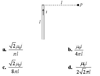
Question. Figure shows a straight wire of length l current i. The magnitude of magnetic field produced by the current at point P is:
Answer : C
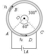
Question. A cell is connected between the points A and C of a circular conductor ABCD of centre 'O' with angle AOC = 60°, If B1 and B2 are the magnitudes of the magnetic fields at O due to the currents in ABC and ADC respectively, the ratio B1 / B2 is:
a. 0.2
b. 6
c. 1
d. 5
Answer : C
Question. For the solenoid shown in figure. The magnetic field at point P is:
Question. A proton of energy 200 MeV enters the magnetic field of 5 T. If direction of field is from south to north and motion is upward, the force acting on it will be:
a. Zero
b. 1.6 10−10 N
c. 3.2 10−8 N
d. 1.6 10−6 N
Answer : B
Question. A particle with 10–11 coulomb of charge and 10–7 kg mass is moving with a velocity of 108 m/s along the y-axis. A uniform static magnetic field B = 0.5 Tesla is acting along the x-direction. The force on the particle is:
a. 5 × 10–11 N along iˆ
b. 5 × 10³ N along k ˆ
c. 5 × 10–11 N along − ˆj
d. 5 × 10⁻⁴ N along − k ˆ
Answer : D
Question. An electron is moving along positive x-axis. To get it moving on an anticlockwise circular path in x-y plane, a magnetic field is applied:
a. Along positive y-axis
b. Along positive z-axis
c. Along negative y-axis
d. Along negative z-axis
Answer : A
Question. The earth’s magnetic field at a given point is 0.5 10-5 Wb-m-2 . This field is to be annulled by magnetic induction at the center of a circular conducting loop of radius 5.0cm. The current required to be flown in the loop is nearly:
a. 0.2 A
b. 0.4A
c. 4A
d. 40A
Answer : B
Question. In the figure shown there are two semicircles of radii r1 and r2 in which a current i is flowing. The magnetic induction at the centre O will be:
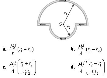
Answer : C
Question. Two very long straight, particle wires carry steady currents i and – i respectively. The distance between the wires is d. At a certain instant of time, a point charge q is at a point equidistant from the two wires, in the plane of the wires. It's instantaneous velocity v is perpendicular to this plane. The magnitude of the force due to the magnetic field acting on the charge at this instant is:
a. μ0iqv / 2πd
b. μ0iqv / πd
c. 2μ0iqv / πd
d. Zero
Answer : D
Question. A metallic block carrying current i is subjected to a uniform magnetic induction B as shown in the figure. The moving charges experience a force F given by ……. which results in the lowering of the potential of the face ……. Assume the speed of the carriers to be v :
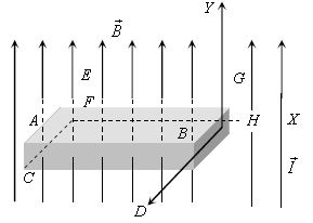
a. eVBkˆ, ABCD
b. eVBkˆ, ABCD
c. −eVBkˆ, ABCD
d. −eVBkˆ,EFGH
Answer : C
Question. A current carrying circular loop is freely suspended by a long thread. The plane of the loop will point in the direction:
a. Wherever left free
b. North-south
c. East-west
d. At 45° with the east-west direction
Answer : C
Question. A particle of charge 16 x 10−18 coulomb moving with velocity 10 m/s along the x-axis enters a region where a magnetic field of induction B is along the y-axis, and an electric field of magnitude 104 V/m is along the negative zaxis. If the charged particle continuous moving along the x-axis, the magnitude of B is:
a. 10−3 Wb /m2
b. 10−3 Wb /m2
c. 10−5 Wb /m2
d. 10−16 Wb /m2
Answer : B
Question. A particle of mass m and charge q moves with a constant velocity v along the positive x direction. It enters a region containing a uniform magnetic field B directed along the negative z direction extending from x = a to x = b. The minimum value of v required so that the particle can just enter the region x > b is:
a. qb B/m
b. q (b – a) B/m
c. qa B/m
d. q (b + a) B/2m
Answer : B
Question. A proton of mass 1.67 x 10⁻²⁷ kg and charge 1.6 x 10⁻¹⁹ C is projected with a speed of 2×10⁶ m/ s at an angle of 60° to the X-axis. If a uniform magnetic field of 0.104 Tesla is applied along Y-axis, the path of proton is:
a. A circle of radius = 0.2 m and time period π ×10−7 s
b. A circle of radius = 0.1 m and time period 2π ×10−7 s
c. A helix of radius = 0.1 m and time period 2π ×10−7 s
d. A helix of radius = 0.2 m and time period 4π ×10−7 s
Answer : B
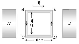
Question. A coil of 50 turns is situated in a magnetic field b = 0.25weber/m2 as shown in figure. A current of 2A is flowing in the coil. Torque acting on the coil will be:
a. 0.15 N
b. 0.3 N
c. 0.45 N
d. 0.6 N
Answer : B
Question. The coil of a galvanometer consists of 100 turns and effective area of 1 square cm. The restoring couple is 10– 8 N-m rad. The magnetic field between the pole pieces is 5 T. The current sensitivity of this galvanometer will be:
a. 5 × 10⁴ rad/μ amp
b. 5 × 10– 6 per amp
c. 2 × 10– 7 per amp
d. 5 rad /μ amp
Answer : D
Question. Consider a magnetic dipole kept in the north south direction. Suppose A1 , A2, B1, B2 be the four points at the same distance from the dipole towards north, south, east and west of the dipole respectively. The directions of the magnetic field due to the dipole are the same at:
a. A1 and A2
b. B1 and B2
c. A1 and B1
d. A2 and B2
Answer : A, B
Question. Which of the following statement (s) is/are correct?
a. Diamagnetism occurs in all materials
b. Diamagnetism is produced due to partial alignment of permanent magnetic dipoles
c. The magnetic field of induced magnetic moment is opposite to the applied field
d. Ferromagnetism is produced due to formation of a large number of small effective regions in the material, called domains and their alignment in external magnetic field
Answer : A, C, D
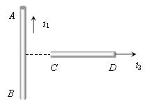
Question. An infinitely long, straight conductor AB is fixed and a current is passed through it. Another movable straight wire CD of finite length and carrying current is held perpendicular to it and released. Neglect weight of the wire:
a. The rod CD will move upwards parallel to itself
b. The rod CD will move downward parallel to itself
c. The rod CD will move upward and turn clockwise at the same time
d. The rod CD will move upward and turn anti –clockwise at the same time
Answer : C
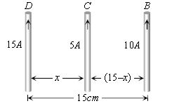
Question. Three long, straight and parallel wires carrying currents are arranged as shown in the figure. The wire C which carries a current of 5.0 amp is so placed that it experiences no force. The distance of wire C from wire D is then:
a. 9 cm
b. 7 cm
c. 5 cm
d. 3 cm
Answer : A
Question. When a ferromagnetic material goes through a hysteresis the magnetic susceptibility:
a. has a fixed value
b. may be zero
c. may be infinity
d. may be negative
Answer : B, C, D
Question. A proton moving with a constant velocity passes through a region of space without any change in any change in its velocity. If E and B represent the electric and magnetic fields respectively. Then, this region of space may have:
a. E = 0, B = 0
b. E = 0, B ≠ 0
c. E ≠ 0, B = 0
d. E ≠ 0, B ≠ 0
Answer : A, B, D
Question. H+ ,He+ and O2+ all having the same kinetic energy pass through a region in which there is a uniform magnetic field perpendicular to their velocity. The masses of H, He+ and O2+ are 1amu, 4amu and 16amu respectively. Then:
a. H+ will be deflected most
b. O2+ will be deflected most
c. He+ and O2+ will be deflected equally
d. all will be deflected equally
Answer : A, C
Question. A micro-ammeter has a resistance of 100Ω and a full scale range of 50 μA. It can be used as a voltmeter or as a high range ammeter provided resistance is added to it. Pick the correct range and resistance combination:
a. 50 V range and 10 KΩ resistance in series
b. 10 V range and 20 KΩ resistance in series
c. 5 mA range with 1Ω resistance in parallel
d. 10 mA range with 1Ω resistance in parallel
Answer : B, C
Question. A dip circle is taken to geomagnetic equator. The needle is allowed to move in a vertical plane perpendicular to the magnetic meridian. Which of the following statements is/are not correct?
a. The needle will stay in a horizontal direction only
b. The needle will stay in vertical direction only
c. The needle will stay in any direction except vertical and horizontal
d. The needle will stay in any direction it is released
Answer : A, B, C
Question. To measure the magnetic moment of a bas magnet, one may use:
a. a tangent galvanometer
b. a deflection galvanometer if the earth’s horizontal field is known
c. an oscillation magnetometer if the earth’s horizontal field is known
d. both deflection and oscillation magnetometer if the earth’s horizontal field is not known
Answer : B, C, D
Question. Which of the following statement is (are) correct in the given figure?
a. net force on the loop is zero
b. net torque on the loop is zero
c. loop will rotate clockwise about axis OO’when seen from O
d. loop will rotate anticlockwise about axis OO’ when seen from O
Answer : A, C
Question. A particle of mass m and charge q, moving with velocity v enters Region II normal to the boundary as shown in the figure. Region II has a uniform magnetic field B perpendicular to the plane of the paper. The length of the Region II is l. Choose the correct choice (s).
a. The particle enters Region III only if its velocity v > qlB / m
b. The particle enters Region III only if its velocity v < qlB / m
c. Path length of the particle in Region II is maximum when velocity
v = qlB / m
d. Time spent in Region II is same for any velocity v as long as the particle returns to Region I
Answer : A, C, D
Question. Two coaxial solenoids 1 and 2 of the same length are set so that one is inside the other. The number of turns per unit length are n1 and n2 . The currents i1 and i2 are flowing in opposite directions. The magnetic field inside the inner coil is zero. This is possible when:
a. i1 ≠ i2 and n1 = n2
b. i1 = i2 and n1 ≠ n2
c. i1 = i2 and n1 = n2
d. i1 n12 = i2 n2
Answer : C, D
Question. H+ , He+ and O++ ions having same kinetic energy pass through a region of space filled with uniform magnetic field B directed perpendicular to the velocity of ions. Th e masses of the ions H+ ,He+ and O++ are respectively in the ratio 1: 4 :16. As a result:
a. H+ ions will be deflected most
b.O++ ions will be deflected least
c. He+ and O++ ions will suffer same deflection
d. All ions will suffer the same deflection
Answer : A, C
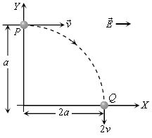
Question. A particle of charge +q and mass m moving under the influence of a uniform electric field Eiˆ and a uniform magnetic field Bkˆ follows trajectory from P to Q as shown in figure. The velocities at P and Q are viˆ and −2vˆj respectively. Which of the following statement(s) is/are correct?
a. E = 3/4 mv2 / qa
b. Rate of work done by electric field at P is 3/4 mv3 / a
c. Rate of work done by electric field at P is zero
d. Rate of work done by both the fields at Q is zero
Answer : A, B, D
Comprehension Based
Paragraph –I
Suppose we have a rectangular bar magnet having length, breadth and mass are L, b and w respectively if it is cut in n equal parts along the length as well as perpendicular to the length simultaneously as shown in the figure then
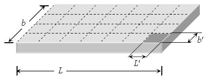
Length of each part L ' = L/√n, breadth of each part b' = b/√n,
Mass of each part w ' = w/n, pole strength of each part m ' = m/√n
Magnetic moment of each part M ' = m' L' = m/√n x L/√n = M/n
Question. A long magnet is cut in two parts in such a way that the ratio of their lengths is 2 : 1. The ratio of pole strengths of both the section is:
a. Equal
b. In the ratio of 2 : 1
c. In the ratio of 1 : 2
d. In the ratio of 4 : 1
Answer : A
Question. A long magnetic needle of length 2L, magnetic moment M and pole strength m units is broken into two pieces at the middle. The magnetic moment and pole strength of each piece will be:
a. ,M/2 , m/2
b. M, m/2
c. M/2 , m
d. M,m
Answer : C
Match the Column
Question. Match the statement of Column with those in Column II:
| Column I | Column II |
| (A) A The magnetism of magnet is due to | 1. Attracts only magnetic substances |
| (B) Magnetic induction is a | 2. Are always closed |
| (C) Magnetic lines of force | 3. Vector quantity |
| (D) A permanent magnet | 4. Magnetic induction force acting on a unit magnetic pole |
a. A → 4, B → 3, C → 2, D → 1
b. A → 2, B → 4, C → 3, D → 1
c. A → 1, B → 3, C → 2, D → 4
d. A → 4, B → 1, C → 3, D → 2
Answer : A
Question. Match the statement of Column with those in Column II:
| Column I | Column II |
| (A) Magnetic field intensity is defined as | 1. The spin motion of electron |
| (B) Which of the following, the most suitable material for making permanent magnet is | 2. Steel |
| (C) In the case of bar magnet, lines of magnetic induction | 3. Run continuously through the bar and outside |
| (D) A sensitive magnetic instrument can be shielded very effectively from outside magnetic fields by placing it inside a box of | 4. Soft iron of high permeability |
a. A → 4, B → 3, C → 2, D → 1
b. A → 2, B → 4, C → 3, D → 1
c. A → 1, B → 2, C → 3, D → 4
d. A → 4, B → 1, C → 3, D → 2
Answer : C
Question. Column I fives certain situations in which a straight metallic wire of resistance R is used and Colum II gives some resulting effects. Match the statements in Column I with the statements in Column II:
| Column I | Column II |
| (A) A charged capacitor is connected to the ends of the wire | 1. A constant current flows through the wire |
| (B) The wire is moved perpendicular to its length with a constant velocity in a uniform magnetic field perpendicular to the plane of motion | 2. Thermal energy is generated in the wire |
| (C) The wire is placed in a constant electric field that has a direction along the length of the wire | 3. A constant potential difference develops between the ends of the wire |
| (D) A battery of constant emf is connected to the ends of the wire | 4. Charges of constant magnitude appear at the ends of the wire |
a. A → 1, B → 3,4, C → 4, D → 2,3
b. A → 2, B → 4 C → 4, D → 1,2,3
c. A → 3,4 B → 2 C → 4, D → 1,2,3
d. A → 2, B → 3,4 C → 4, D → 1,2,3
Answer : D
Please click the link below to download CBSE Class 12 Physics Electromagnetic Induction And Alternating Currents chapter notes and important questions.
Free study material for Physics
Free CBSE Study Guides: Class 12 Physics Chapter 06 Electromagnetic Induction
Core Study Kit: Class 12 Physics Chapter 06 Electromagnetic Induction
Access comprehensive study material for Chapter 06 Electromagnetic Induction, including revision notes, concept maps, and high-probability questions. These resources are designed in alignment with the latest 2026 CBSE syllabus for Class 12 Physics to support effective exam preparation.
NCERT-Aligned Solutions for Chapter 06 Electromagnetic Induction
Designed around the official curriculum, these study guides guarantee standard compliance. Reviewing step-by-step solutions clarifies complex sub-topics within Chapter 06 Electromagnetic Induction and demystifies standard marking schemes for Physics evaluations.
Next Steps in Your Exam Preparation
Wrap up your chapter revision by testing your knowledge against standard objective question formats. Explore our full library of free, up-to-date sample papers and online assessments to secure top grades in your CBSE examinations.
FAQs
Our advanced study package for Chapter 06 Electromagnetic Induction includes detailed concepts, diagrams, Mind Maps, and explanation of complex topics to ensure Class 12 students learn as per syllabus for 2026 exams.
The Mind Maps provided for Chapter 06 Electromagnetic Induction act as visual anchors which will help faster recall during high-pressure exams.
Yes, teachers use our Class 12 Physics resources for lesson planning as they are in simple language and have lot of solved examples.
Yes, You can download the complete, mobile-friendly PDF of the Physics Chapter 06 Electromagnetic Induction advanced resources for free.
Yes, our subject matter experts have updated the Chapter 06 Electromagnetic Induction material to align with the rationalized NCERT textbooks and have removed deleted topics and added new competency-based questions.