

Official CBSE Study Materials for Class 12 Physics
Explore structured advanced study materials through the CBSE Class 12 Physics Electromagnetic Induction Alternating Current Frequently Asked Questions. Tailored for Class 12 learners, utilizing these Physics resources ensures thorough preparation and strengthens foundational knowledge before final CBSE evaluations.
Advanced Resources for Physics
Access the complete useful resource PDF for Class 12 Physics below. Regular practice with these targeted academic notes builds familiarity with complex topics and helps secure higher marks in final school evaluations.
CBSE Class 12 Physics Electromagnetic Induction Alternating Current Frequently Asked Questions. There are many more useful educational material which the students can download in pdf format and use them for studies. Study material like concept maps, important and sure shot question banks, quick to learn flash cards, flow charts, mind maps, teacher notes, important formulas, past examinations question bank, important concepts taught by teachers. Students can download these useful educational material free and use them to get better marks in examinations. Also refer to other worksheets for the same chapter and other subjects too. Use them for better understanding of the subjects.
ELECTROMAGNETIC INDUCTION & ALTERNATING CURRENT
1 MARKS
1. How does the self-inductance of an air core coil change, when (i) the number of turns in the coils is decreased & (ii) an iron rod is introduced in the coil? [1 Mark]
Answer:
1. Self-inductance is given by L = \(\mu_0 n^2 A l\), showing L is directly proportional to the square of the number of turns.
2. (i) When the number of turns is decreased, the self-inductance decreases.
3. (ii) When an iron rod of high permeability is introduced, the magnetic permeability increases, so the self-inductance increases.
Teacher's Note:
a) Self-inductance measures a coil's opposition to the change in current.
b) Core material significantly affects inductance due to magnetic permeability.
2. What is the effect on the mutual inductance between the pair of coil when (i) the distance between the coils is increased?(ii) the number of turns in each coil is decreased? Justify your answer in each case [1 Mark]
Answer:
1. (i) When the distance between the coils is increased, the magnetic flux linkage decreases, so mutual inductance decreases.
2. (ii) Mutual inductance is directly proportional to the product of the number of turns in both coils, so decreasing the turns decreases the mutual inductance.
Teacher's Note:
a) Mutual inductance depends on geometry, distance, and orientation of the coils.
b) Tightly coupled coils have a higher mutual inductance value.
3. State Lenz’s law. Show that it is in accordance with the law of conservation of energy. [1 Mark]
Answer:
1. Lenz's law states that the polarity of induced emf is such that it tends to produce a current which opposes the change in magnetic flux that produces it.
2. Mechanical work done in moving a magnet against the opposing force gets converted into electrical energy, satisfying conservation of energy.
Teacher's Note:
a) The negative sign in Faraday's law mathematically represents Lenz's law.
b) Violating Lenz's law would mean creating energy out of nothing, which is impossible.
4. The closed loop PQRS is moving into uniform magnetic field acting at right angles to the plane of the paper as shown. State the direction of the induced current in the loop. [1 Mark]
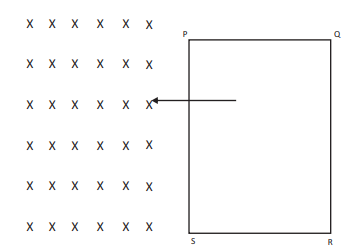
[Figure: A rectangular loop PQRS entering a uniform cross magnetic field region marked by crosses X pointing into the page. The left edge enters first perpendicular to the boundary field.]
Answer:
1. As the loop enters the magnetic field, the magnetic flux linked with the loop increases inward.
2. According to Lenz's law, the induced current will oppose this increase by producing outward magnetic flux.
3. Therefore, the direction of the induced current is anticlockwise along P - Q - R - S - P.
Teacher's Note:
a) Use Fleming's right-hand rule or Lenz's law to determine current direction.
b) The induced current flows in a direction to oppose the cause producing it.
5. Define mutual inductance and give its S.I. Unit. Write two factors on which the mutual- inductance between a pair of coil depends. [1 Mark]
Answer:
1. Mutual inductance is defined as the magnetic flux linked with the secondary coil when unit current flows through the primary coil.
2. S.I. unit of mutual inductance is Henry (H) or Wb/A.
3. Two factors are: (i) geometry and number of turns of the coils, and (ii) magnetic permeability of the core medium.
Teacher's Note:
a) Mutual induction is the principle behind the working of transformers.
b) Mentioning units clearly avoids loss of marks in board evaluations.
6. What is the power dissipated in an ac circuit in which voltage & current are given by V = 230 sin (\(\omega\)t + \(\pi\)/2) and I = 10 sin \(\omega\)t? [1 Mark]
Answer:
1. Given voltage V = 230 sin (\(\omega\)t + \(\frac{\pi}{2}\)) and current I = 10 sin (\(\omega\)t).
2. Phase difference between voltage and current is \(\phi = \frac{\pi}{2}\).
3. Average power P = \(V_{rms} I_{rms} \cos(\phi)\).
4. Since \(\cos(\frac{\pi}{2}) = 0\), the power dissipated is zero.
Teacher's Note:
a) A purely inductive or capacitive circuit consumes zero average power.
b) The current in this circuit is known as wattless current.
7. The instantaneous current & voltage of an ac circuit are given by: i = 10 sin 314t ampere & V = 50 sin 314t volt. What is the power dissipation in th circuit? [1 Mark]
Answer:
1. Given i = 10 sin (314t) and V = 50 sin (314t).
2. Phase angle between voltage and current is \(\phi = 0^\circ\).
3. Root mean square voltage \(V_{rms} = \frac{50}{\sqrt{2}}\) and \(I_{rms} = \frac{10}{\sqrt{2}}\).
4. Power P = \(V_{rms} I_{rms} \cos(0^\circ) = \frac{50}{\sqrt{2}} \times \frac{10}{\sqrt{2}} \times 1 = \frac{500}{2}\) = 250 W.
Teacher's Note:
a) Zero phase difference means the circuit is purely resistive.
b) Always calculate RMS values from peak values before computing power.
8. The coils in certain galvanometers have fixed core made of a non-magnetic material. Why doesthe oscillating coil come to rest so quickly in such a core? [1 Mark]
Answer:
1. When the coil oscillates, magnetic flux linked with the non-magnetic metal core changes.
2. This induces strong eddy currents in the core.
3. According to Lenz's law, these eddy currents oppose the motion of the coil.
4. As a result, the oscillating coil comes to rest quickly due to electromagnetic damping.
Teacher's Note:
a) This phenomenon is known as electromagnetic damping or dead-beat motion in galvanometers.
b) The metal core must be non-magnetic so that it does not experience magnetic attraction, only damping due to eddy currents.
9. What are eddy currents? How are these produced? In what sense are eddy currents considered undesirable in a transformer and how are these reduced in such a device? [3 Marks]
Answer:
1. Eddy currents are swirling loops of induced electric current circulating within conductors, induced by changing magnetic fields.
2. They are produced when a bulk piece of conductor is placed in a changing magnetic flux.
3. They are undesirable in transformers because they cause energy dissipation in the form of heat, leading to power loss.
4. They are reduced by using laminated iron cores where thin sheets of metal are insulated from each other to restrict the paths of eddy currents.
Teacher's Note:
a) Eddy currents are also called Foucault currents.
b) Lamination increases the resistance of the path, drastically reducing the magnitude of eddy currents and minimizing heat loss.
c) Mentioning both the cause (changing flux) and the remedy (lamination) ensures full credit in board examinations.
10. Prove that average power consumed over a complete cycle of ac through an ideal inductor is zero. [3 Marks]
Answer:
1. In an ideal inductor, current lags behind the alternating voltage by a phase angle of \(\frac{\pi}{2}\).
2. Let voltage be \(e = e_0 \sin(\omega t)\) and current be \(i = i_0 \sin(\omega t - \frac{\pi}{2}) = -i_0 \cos(\omega t)\).
3. Instantaneous power is given by \(P = e i = e_0 \sin(\omega t) \times (-i_0 \cos(\omega t)) = -e_0 i_0 \sin(\omega t)\cos(\omega t) = -\frac{e_0 i_0}{2} \sin(2\omega t)\).
4. The average value of \(\sin(2\omega t)\) over a complete cycle is zero, hence average power consumed is zero.
Teacher's Note:
a) An ideal inductor is purely inductive with zero resistance, so power factor is zero.
b) Energy is stored in the magnetic field during a quarter cycle and returned to the source in the next quarter cycle.
c) Show the integration or explicit sine wave average property clearly when writing this derivation.
11. Prove that an ideal capacitor in an ac circuit does not dissipate power. [3 Marks]
Answer:
1. In an ideal capacitor connected to an alternating voltage, current leads the voltage by a phase angle of \(\frac{\pi}{2}\).
2. Let alternating voltage be \(e = e_0 \sin(\omega t)\) and current be \(i = i_0 \sin(\omega t + \frac{\pi}{2}) = i_0 \cos(\omega t)\).
3. Instantaneous power is \(P = e i = e_0 i_0 \sin(\omega t)\cos(\omega t) = \frac{e_0 i_0}{2} \sin(2\omega t)\).
4. The average of \(\sin(2\omega t)\) over a complete cycle is zero, proving that an ideal capacitor dissipates no net power.
Teacher's Note:
a) The average power formula is \(P_{avg} = V_{rms} I_{rms} \cos\phi\), where phase angle \(\phi = \frac{\pi}{2}\), making \(\cos(\frac{\pi}{2}) = 0\).
b) Capacitors store electrostatic energy during charging and return it to the source during discharging.
c) Use clear trigonometric identities to demonstrate the zero average of the sine double-angle term.
12. Distinguish resistance, reactance and impedance. [3 Marks]
Answer:
| Property | Resistance (R) | Reactance (X) | Impedance (Z) |
|---|---|---|---|
| Definition | Opposition offered by a conductor to the flow of direct or alternating current. | Opposition offered by an inductor or capacitor to alternating current. | Total opposition offered to AC by a circuit containing R, L, and C elements. |
| Dependence on Frequency | Independent of frequency (for ideal resistors). | Depends on frequency (\(X_L = \omega L\), \(X_C = \frac{1}{\omega C}\)). | Depends on frequency as it includes reactance components. |
| Power Dissipation | Dissipates electrical energy as heat. | Does not dissipate electrical energy; stores and returns it. | Dissipates power only across its resistive part. |
Teacher's Note:
a) All three quantities are measured in ohms (Ω).
b) Impedance is the vector sum of resistance and net reactance: \(Z = \sqrt{R^2 + (X_L - X_C)^2}\).
c) Clear tabular differentiation is preferred by examiners for comparison questions.
13. What is an induced emf ? Write Faraday’s law of electroma genetic induction Express it mathematically. [3 Marks]
Answer:
1. Induced emf is the potential difference or electromotive force generated in a circuit or conductor when there is a change in magnetic flux linked with it.
2. Faraday's first law states that whenever magnetic flux linked with a closed circuit changes, an emf is induced in it.
3. Faraday's second law states that the magnitude of the induced emf is directly proportional to the rate of change of magnetic flux linked with the circuit.
4. Mathematically, induced emf is expressed as \(e = -\frac{d\Phi}{dt}\), where \(\Phi\) is magnetic flux and the negative sign represents Lenz's law.
Teacher's Note:
a) Ensure the spelling typo in the question paper ("electroma genetic") is understood as electromagnetic induction.
b) The negative sign is crucial as it signifies the direction of induced emf in accordance with conservation of energy.
c) For a coil with N turns, the expression becomes \(e = -N \frac{d\Phi}{dt}\).
SECTION: 2 MARKS
15. Derive an expression for: (i) induced emf & (ii) induced current when, a conductor of length is moved into a uniform velocity v normal to a uniform magnetic field B. Assume resistance of conductor to be R. [2 Marks]
Answer:
1. Let a conductor of length \(l\) move with velocity \(v\) perpendicular to a uniform magnetic field \(B\). In time \(dt\), the area swept by the conductor is \(dA = l v dt\).
2. Change in magnetic flux is \(d\Phi = B \cdot dA = B l v dt\).
3. (i) Induced emf is given by magnitude \(e = \frac{d\Phi}{dt} = B l v\).
4. (ii) Induced current is given by Ohm's law as \(I = \frac{e}{R} = \frac{B l v}{R}\).
Teacher's Note:
a) This is known as motional electromotive force.
b) Both sub-parts must be clearly labelled to secure full marks in 2-mark questions.
16. Derive an expression for average power consumed over a complete cycle of ac through an LCR circuit. [2 Marks]
Answer:
1. In an LCR circuit, alternating voltage is \(e = e_0 \sin(\omega t)\) and current is \(i = i_0 \sin(\omega t - \phi)\), where \(\phi\) is the phase angle.
2. Instantaneous power \(P = e i = e_0 i_0 \sin(\omega t) \sin(\omega t - \phi)\).
3. Expanding and taking the average over a complete cycle, the average power becomes \(P_{avg} = \frac{e_0 i_0}{2} \cos\phi\).
4. Expressing in terms of RMS values, \(P_{avg} = V_{rms} I_{rms} \cos\phi\).
Teacher's Note:
a) Term \(\cos\phi\) is called the power factor of the circuit.
b) Power is dissipated only in the resistive part of the LCR circuit.
17. Define mutual inductance and give its SI unit. Derive an expression for the mutual inductance of two long coaxial solenoids of same length wound over the other. [2 Marks]
Answer:
1. Mutual inductance is the property of two coils by virtue of which an opposing emf is induced in one coil when current changes in the neighbouring coil. Its SI unit is Henry (H).
2. Consider two long coaxial solenoids each of length \(l\) and radius \(r_1\) and \(r_2\) (\(r_1 \lt r_2\)) with total turns \(N_1\) and \(N_2\).
3. Magnetic field inside solenoid 1 due to current \(I_1\) is \(B_1 = \mu_0 \frac{N_1}{l} I_1\).
4. Flux linked with solenoid 2 is \(\Phi_2 = N_2 B_1 A_1 = N_2 \left(\mu_0 \frac{N_1}{l} I_1\right) (\pi r_1^2)\). Using \(\Phi_2 = M I_1\), mutual inductance is \(M = \frac{\mu_0 N_1 N_2 \pi r_1^2}{l}\).
Teacher's Note:
a) Mutual inductance depends on geometry, number of turns, and magnetic permeability of the core.
b) Reciprocity theorem holds: \(M_{12} = M_{21} = M\).
18. Define self-inductance and give its S. I. Unit. Derive an expression for self-inductance of a long, air-cored solenoid of length l, radius r, and having N number of turns [2 Marks]
Answer:
1. Self-inductance is the property of a coil by virtue of which it opposes any change in the strength of current flowing through it by inducing an opposing emf in itself. Its SI unit is Henry (H).
2. Magnetic field inside a long air-cored solenoid carrying current \(I\) is \(B = \mu_0 \frac{N}{l} I\).
3. Total magnetic flux linked with the solenoid of \(N\) turns and cross-sectional area \(A = \pi r^2\) is \(\Phi = N B A = N \left(\mu_0 \frac{N}{l} I\right) (\pi r^2)\).
4. Since \(\Phi = L I\), self-inductance is \(L = \frac{\mu_0 N^2 \pi r^2}{l}\).
Teacher's Note:
a) Self-inductance acts as the electrical equivalent of inertia in mechanics.
b) Clearly state the formula \(L = \frac{\Phi}{I}\) before substituting the magnetic field.
SECTION: 3 MARKS
19. Explain the term 'capacitive reactance'. Show graphically the variation of capacitive reactance with frequency of the applied alternating voltage. An a.c. voltage E=E_0\sin(\omega t) is applied across a pure capacitor of capacitance C. Show mathematically that the current flowing through it leads the applied voltage by a phase angle of \(\pi\)/2. [3 Marks]
Answer:
1. Capacitive reactance is the opposition offered by a capacitor to the flow of alternating current, given by \(X_C = \frac{1}{\omega C} = \frac{1}{2\pi f C}\).
2. Graphically, \(X_C\) is inversely proportional to frequency \(f\), represented by a rectangular hyperbola curve sloping downwards as frequency increases.
3. Given voltage \(e = e_0 \sin(\omega t)\). Charge on capacitor is \(q = C e = C e_0 \sin(\omega t)\).
4. Current is \(i = \frac{dq}{dt} = \frac{d}{dt} [C e_0 \sin(\omega t)] = \omega C e_0 \cos(\omega t) = \frac{e_0}{X_C} \sin(\omega t + \frac{\pi}{2})\), showing current leads voltage by \(\frac{\pi}{2}\).
Teacher's Note:
a) Capacitive reactance decreases with an increase in frequency and becomes zero for direct current (infinite reactance for DC).
b) The differentiation step \(\frac{dq}{dt}\) connects charge directly to current in a capacitive circuit.
c) The phase relationship of leading by \(\frac{\pi}{2}\) is a fundamental property of pure capacitive AC circuits.
20. Explain the term 'inductive reactance'. Show graphically the variation of inductive reactance with frequency of the applied alternating voltage. [3 Marks]
An a.c. Voltage \(E = E_0 \sin\omega t\) is applied across a pure inductor of inductance L. Show mathematically that the current flowing through it lags behind the applied voltage by a phase angle of \(\pi/2\).
Answer:
1. Inductive reactance is the opposition offered by an inductor to the flow of alternating current, given by \(X_L = \omega L = 2\pi f L\).
2. The variation of \(X_L\) with frequency f is a straight line passing through the origin because \(X_L\) is directly proportional to f.
3. Applying Kirchhoff's loop rule to the inductive circuit: \(E - L \frac{di}{dt} = 0\), so \(\frac{di}{dt} = \frac{E_0 \sin\omega t}{L}\).
4. Integrating both sides: \(i = \int \frac{E_0}{L} \sin\omega t \, dt = -\frac{E_0}{\omega L} \cos\omega t = \frac{E_0}{\omega L} \sin\left(\omega t - \frac{\pi}{2}\right)\).
5. Thus, the current is \(i = I_0 \sin\left(\omega t - \frac{\pi}{2}\right)\), which clearly shows that current lags behind the applied voltage by a phase angle of \(\pi/2\).
Teacher's Note:
a) Inductive reactance depends directly on both the inductance and the frequency of the AC source.
b) Students often confuse current lagging in inductors with current leading in capacitors.
c) Remember that a pure inductor consumes no average power over a complete cycle.
21. An AC source of voltage V = Vm sin \(\omega t\) is applied across a series LCR circuit. Draw the phasor diagrams for this circuit, when: [3 Marks]
a) Capacitive impedance exceeds the inductive impedance and
b) Inductive impedance exceeds capacitive impedance.
Answer:
1. In a series LCR circuit, the net reactance determines whether the circuit is capacitive or inductive.
2. Case (a) When capacitive reactance exceeds inductive reactance (\(X_C \gt X_L\)), the net reactance is capacitive, and current leads the source voltage.
3. Case (b) When inductive reactance exceeds capacitive reactance (\(X_L \gt X_C\)), the net reactance is inductive, and current lags behind the source voltage.
4. Phasor diagrams illustrate the phase relationship between current vector along the reference axis and the voltage vectors \(V_R\), \(V_L\), and \(V_C\).
Teacher's Note:
a) Always draw current as the reference phasor along the horizontal axis for series circuits.
b) Ensure the resultant voltage triangle correctly reflects the vector difference between \(V_L\) and \(V_C\).
c) Mentioning the impedance angle \(\phi\) clearly adds value to the explanation.
22. A coil of inductance 'L', a capacitor of capacitance 'C', & a resistor of resistance 'R' are all put in series with an alternating source of emf E = E0 sin \(\omega t\). Write expressions for a) total impedance of circuit, and (b) frequency of source emf for which circuit will show resonance. [2 Marks]
Answer:
1. (a) The total impedance Z of a series LCR circuit is given by \(Z = \sqrt{R^2 + (X_L - X_C)^2} = \sqrt{R^2 + \left(\omega L - \frac{1}{\omega C}\right)^2}\).
2. (b) Resonance occurs when the inductive reactance equals the capacitive reactance, meaning \(\omega L = \frac{1}{\omega C}\).
3. Solving for resonant angular frequency \(\omega_r = \frac{1}{\sqrt{LC}}\), the linear resonant frequency is given by \(f_r = \frac{1}{2\pi\sqrt{LC}}\).
Teacher's Note:
a) Impedance represents the total effective opposition of an LCR circuit to alternating current.
b) At resonance, impedance is at its minimum value and equals resistance R.
c) Units must be included for frequency (Hz) and impedance (ohms).
23. A circular coil of N-turns & radius 'R' is kept normal to a magnetic field, given by: B = B0 cos \(\omega t\). Deduce an expression for the emf induced in this coil. State the rule which helps to detect the direction of induced current. [3 Marks]
Answer:
1. The area of the circular coil is \(A = \pi R^2\).
2. The magnetic flux linked with the N-turns coil at any time t is \(\Phi = N B A \cos\omega t = N (\pi R^2) B_0 \cos(\omega t) \cos\omega t = N \pi R^2 B_0 \cos^2\omega t\).
3. Using Faraday's law, the induced emf is \(e = -\frac{d\Phi}{dt} = -N \pi R^2 B_0 \frac{d}{dt}(\cos^2\omega t) = -N \pi R^2 B_0 (2\cos\omega t)(-\sin\omega t)(\omega)\).
4. Simplifying the expression yields \(e = N \pi R^2 B_0 \omega \sin(2\omega t)\).
5. Lenz's law helps to detect the direction of the induced current.
Teacher's Note:
a) Pay careful attention to the chain rule when differentiating composite trigonometric functions.
b) Lenz's law is based on the law of conservation of energy.
c) The negative sign in Faraday's law indicates the direction of the induced emf.
24. Discuss a series resonant circuit. Derive an expression for resonant frequency and show a graphical variation between current and angular frequency of applied ac. Define quality factor and derive an expression for it. [5 Marks]
Answer:
1. A series resonant circuit consists of an inductor, capacitor, and resistor connected in series across an AC source.
2. Resonance occurs when inductive reactance equals capacitive reactance, so \(\omega_r L = \frac{1}{\omega_r C}\), giving resonant frequency \(\omega_r = \frac{1}{\sqrt{LC}}\).
3. At resonance, impedance is minimum (\(Z = R\)) and alternating current is maximum.
4. The quality factor (Q-factor) measures the sharpness of resonance and is defined as the ratio of voltage across the inductor or capacitor to the source voltage, expressed as \(Q = \frac{\omega_r L}{R} = \frac{1}{R}\sqrt{\frac{L}{C}}\).
Teacher's Note:
a) A higher Q-factor indicates a sharper resonance curve and better selectivity.
b) The current versus frequency graph peaks sharply at the resonant frequency.
c) Bandwidth is inversely proportional to the quality factor of the circuit.
d) Always verify dimensional consistency when deriving dimensionless parameters like the Q-factor.
25. Explain with help of a labelled diagram the principle, construction and working of a transformer. Mention the various energy losses in a transformer? Explain the role of transformer in long distance transmission of power? [5 Marks]
Answer:
1. Principle: A transformer works on the principle of mutual induction between two coils.
2. Construction: It consists of a laminated soft iron core with a primary coil and a secondary coil wound on it.
3. Working: When an alternating voltage is applied to the primary coil, a changing magnetic flux is set up in the core, which induces an alternating emf in the secondary coil.
4. Energy losses include copper loss, iron loss (eddy current and hysteresis losses), flux leakage, and Joule heating.
5. Role in transmission: Power is transmitted at very high voltage and low current over long distances to minimize \(I^2R\) power losses in transmission cables.
Teacher's Note:
a) Mentioning transformer turns ratio \(\frac{V_s}{V_p} = \frac{N_s}{N_p}\) is essential for full credit.
b) Laminated cores are specifically used to minimize eddy current energy losses.
c) Step-up transformers are used at power generating stations, while step-down transformers are used at distribution points.
d) An ideal transformer assumes 100 percent efficiency with zero power loss.
26. With the help of a neat diagram, explain the principle construction and working of an a.c generator. [5 Marks]
Answer:
1. Principle: An AC generator works on the principle of electromagnetic induction; when a coil is rotated in a uniform magnetic field, the magnetic flux linked with it changes continuously, inducing an alternating emf.
2. Construction: It consists of a strong field magnet, an armature coil, slip rings, and carbon brushes.
3. Working: As the armature coil is rotated mechanically in the magnetic field, the magnetic flux linked with the coil changes sinusoidally with time.
4. By Fleming's right-hand rule, the induced current changes direction every half rotation, producing an alternating current with instantaneous emf \(e = NBA\omega \sin\omega t\).
Teacher's Note:
a) Slip rings ensure continuous connection between the rotating coil and the external circuit.
b) The magnitude of the induced emf depends on the number of turns, magnetic field strength, area, and angular velocity.
c) Brushes remain stationary while slip rings rotate along with the armature coil.
d) Energy conversion transforms mechanical energy into electrical energy.
Free study material for Physics
Useful Resources and Notes for Class 12 Physics Chapter 06 Electromagnetic Induction
Quick Revision Material for Chapter 06 Electromagnetic Induction
Explore essential learning tools for Class 12 Physics Chapter 06 Electromagnetic Induction. This curated collection features in-depth notes and targeted practice questions built around the active 2026 curriculum to streamline your daily revision.
Expert Notes and Solved Exam Questions
Designed around the official curriculum, these study guides guarantee standard compliance. Reviewing step-by-step solutions clarifies complex sub-topics within Chapter 06 Electromagnetic Induction and demystifies standard marking schemes for Physics evaluations.
Additional Study Resources for Class 12
Wrap up your chapter revision by testing your knowledge against standard objective question formats. Explore our full library of free, up-to-date sample papers and online assessments to secure top grades in your CBSE examinations.
FAQs
Our advanced study package for Chapter 06 Electromagnetic Induction includes detailed concepts, diagrams, Mind Maps, and explanation of complex topics to ensure Class 12 students learn as per syllabus for 2026 exams.
The Mind Maps provided for Chapter 06 Electromagnetic Induction act as visual anchors which will help faster recall during high-pressure exams.
Yes, teachers use our Class 12 Physics resources for lesson planning as they are in simple language and have lot of solved examples.
Yes, You can download the complete, mobile-friendly PDF of the Physics Chapter 06 Electromagnetic Induction advanced resources for free.
Yes, our subject matter experts have updated the Chapter 06 Electromagnetic Induction material to align with the rationalized NCERT textbooks and have removed deleted topics and added new competency-based questions.