

Official CBSE Study Materials for Class 12 Physics
Explore structured advanced study materials through the CBSE Class 12 Physics Electromagnetic Induction Advanced Problems. Tailored for Class 12 learners, utilizing these Physics resources ensures thorough preparation and strengthens foundational knowledge before final CBSE evaluations.
Advanced Resources for Physics
Navigate directly to the advanced Physics study materials using the digital viewer below. Each resource pack includes detailed conceptual summaries and solved practice questions, allowing students to instantly reinforce their learning.
Filename. Please refer to the examination notes which you can use for preparing and revising for exams. These notes will help you to revise the concepts quickly and get good marks.
CLASS 12 PHYSICS : ELECTROMAGNETIC INDUCTION
ADVANCED PROBLEMS
1. Two parallel vertical metallic rails AB and CD are separated by 1 m. They are connected at the two ends by resistances R1 and R2 as shown in the figure. A horizontal metallic bar L of mass 0.2 kg slides without friction, vertically down the rails under the action of gravity. There is a uniform horizontal magnetic field of 0.6 T perpendicular to the plane of the rails. It is observed that when the terminal velocity is attained, the power dissipated in R1 and R2 are 0.76 W and 1.2 W respectively. Find the terminal velocity of the bar L and the values of R1 and R2 .
[Figure: Two parallel vertical rails AB (left) and CD (right), 1 m apart, with A and C at the top and B and D at the bottom. Resistor R1 joins A and C at the top and resistor R2 joins B and D at the bottom. A horizontal metallic bar L slides down across the two rails between R1 and R2]
Answer: Terminal velocity = 1 m/s; R1 = \( \frac{9}{19} \) Ω; R2 = 0.3 Ω.
1. At terminal velocity, the loss of gravitational potential energy per second equals the electrical power dissipated: m g v = P1 + P2.
2. 0.2 × 9.8 × v = 0.76 + 1.2 = 1.96, so v = 1 m/s.
3. The e.m.f. across the bar = B l v = 0.6 × 1 × 1 = 0.6 V, and this is the voltage across both R1 and R2 (they are in parallel across the bar).
4. R1 = \( \frac{V^{2}}{P_1} \) = \( \frac{0.36}{0.76} \) = \( \frac{9}{19} \) Ω ≈ 0.47 Ω.
5. R2 = \( \frac{V^{2}}{P_2} \) = \( \frac{0.36}{1.2} \) = 0.3 Ω.
Teacher's Note:
a) At terminal speed the magnetic force B I l balances the weight, so mg v equals the electrical power.
b) Take g = 9.8 m/s²; the bar is treated as having negligible resistance.
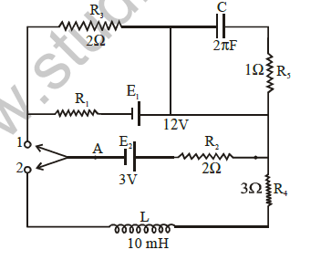
2. A circuit containing a two position switch S is shown in the figure.
(a) The switch S is in position 1. Find the potential difference (VA-VB) and the rate of production of joule heat in R1.
(b) If now the switch S is put in position 2 at t = 0, find
(i) steady current in R4 and
(ii) the time when the current in R4 is half the steady value. Also calculate the energy stored in the inductor L at that time.

[Figure: A circuit with a two-position switch S. Position 1 connects the pole A to the left wire; position 2 connects it to the lower wire containing the inductor L = 10 mH, which returns through R4 = 3 Ω. The pole A is joined through cell E2 (3 V) and R2 = 2 Ω to the right-hand vertical wire. The left wire is joined to the top wire through R3 = 2 Ω, then to a capacitor C = 2π F in series with R5 = 1 Ω on the right-hand wire, and through R1 and cell E1 (12 V) to the right-hand wire. A vertical wire joins the top wire between R3 and C to the wire carrying E1]
Answer:
1. (a) In position 1 the switch pole A is joined to the left wire. The right end of R3 (through the top wire), the right end of E1 and the right end of R2 are all joined to the right-hand vertical wire; call this common point N. The capacitor C in series with R5 is connected from N back to N, so it carries no current.
2. Between the left wire and N three branches are in parallel: R3 = 2 Ω; E1 (12 V) with R1; E2 (3 V) with R2 = 2 Ω. The positive plates of both cells are towards N. The figure does not print R1; the printed key VA - VB = -5 V corresponds to R1 = 2 Ω, which is used here.
3. Let V = VA - VB. The junction rule gives \( \frac{V}{2} \) + \( \frac{V + 12}{2} \) + \( \frac{V + 3}{2} \) = 0, so 3V = -15 and VA - VB = -5 V.
4. Current in R1 = \( \frac{-5 + 12}{2} \) = 3.5 A, so the rate of heat production in R1 = (3.5)² × 2 = 24.5 W.
5. (b)(i) In position 2, the loop is E2, R2, R4 and L in series. In the steady state the inductor has no voltage across it: I = \( \frac{3}{2 + 3} \) = 0.6 A.
6. (b)(ii) The current grows as I = 0.6(1 - e-t/τ), where τ = \( \frac{L}{R} \) = \( \frac{10 \times 10^{-3}}{5} \) = 2 × 10⁻³ s.
7. For I = 0.3 A, e-t/τ = 0.5, so t = τ ln 2 = 2 × 10⁻³ × 0.693 = 1.38 × 10⁻³ s.
8. Energy stored in L = \( \frac{1}{2} \) L I² = \( \frac{1}{2} \) × 10 × 10⁻³ × (0.3)² = 4.5 × 10⁻⁴ J.
Teacher's Note:
a) In the steady state of an L-R circuit the inductor acts as a plain wire, and the capacitor branch carries no current.
b) The energy stored depends on the instantaneous current (0.3 A), not on the steady current.
c) The figure does not give a value for R1; the value 2 Ω reproduces the printed key of -5 V.
3. A current i = 3.36 (1+2 t) × 10⁻² A increases at a steady rate in long straight wire. A small circular loop of radius 10⁻³ m has its plane parallel to the wire and is placed at a distance of 1 m from the wire. The resistance of the loop is 8.4 × 10⁻⁴ Ω. Fine the magnitude and direction of induced current in the loop.
Answer: Induced current = 5 × 10⁻¹¹ A
1. Magnetic field of the wire at the loop, B = \( \frac{μ_0 i}{2π d} \), and it is uniform over the small loop.
2. Flux through the loop = B π r² = \( \frac{μ_0 i r^{2}}{2d} \).
3. e.m.f. = \( \frac{μ_0 r^{2}}{2d} \) \( \frac{di}{dt} \) with \( \frac{di}{dt} \) = 3.36 × 2 × 10⁻² = 6.72 × 10⁻² A/s.
4. e.m.f. = \( \frac{4π \times 10^{-7} \times 10^{-6} \times 6.72 \times 10^{-2}}{2 \times 1} \) ≈ 4.2 × 10⁻¹⁴ V.
5. Induced current = \( \frac{4.2 \times 10^{-14}}{8.4 \times 10^{-4}} \) = 5 × 10⁻¹¹ A.
6. As the current in the wire increases, the flux through the loop increases, so by Lenz's law the induced current flows in the sense that produces a magnetic field opposite to the field of the wire at the loop.
Teacher's Note:
a) The loop is so small that the field is taken as uniform over its area.
b) Direction always follows Lenz's law: the induced field opposes the increase of flux.
4. Two coaxial circular loops of radii 0.5 m and 5 × 10⁻² m are separated by a distance 0.5 m and carry currents 2A and 1A respectively. Calculate their mutual inductance. What is the force between the loops?
Answer: M ≈ 3.49 × 10⁻⁹ H; force ≈ 2.09 × 10⁻⁸ N
1. For the small loop (radius r) on the axis of the large loop (radius R) at distance x, flux = B π r² with B = \( \frac{μ_0 R^{2} I}{2(R^{2} + x^{2})^{3/2}} \).
2. M = \( \frac{μ_0 π R^{2} r^{2}}{2(R^{2} + x^{2})^{3/2}} \).
3. R² + x² = 0.25 + 0.25 = 0.5, so (R² + x²)3/2 = 0.354.
4. M = \( \frac{4π \times 10^{-7} \times π \times 0.25 \times 0.0025}{2 \times 0.354} \) ≈ 3.49 × 10⁻⁹ H.
5. Force F = I1 I2 \( \frac{dM}{dx} \), and \( \frac{dM}{dx} \) = -\( \frac{3 M x}{R^{2} + x^{2}} \) in magnitude = \( \frac{3 \times 3.49 \times 10^{-9} \times 0.5}{0.5} \) ≈ 1.05 × 10⁻⁸ H/m.
6. F = 2 × 1 × 1.05 × 10⁻⁸ ≈ 2.09 × 10⁻⁸ N.
7. The force is attractive if the currents flow in the same sense and repulsive if they flow in opposite senses.
Teacher's Note:
a) The force between current loops is I1 I2 times the rate of change of mutual inductance with separation.
b) The magnitude is tiny because the small loop has a radius of only 5 cm.
5. Two long straight parallel wires A and B are separated by 0.1 m distance and carry equal currents in opposite directions. A square loop of wire C of side 0.1 m lies in the plane of A and B. A thin loop of wire C is kept parallel to both A and B at a distance of 0.1 m from the nearest wire. Calculate the emf induced in the loop C while the current in A and B is increasing at the same rate of 10³ A s⁻¹. Also indicate the direction of current in loop C
[Figure: Two long vertical wires A (current I2 upward) and B (current I1 downward), 0.1 m apart, in the plane of the paper. A square loop C of side 0.1 m lies to the right of B in the same plane, with its nearest side 0.1 m from B]
Answer: e.m.f. ≈ 5.75 μV; the induced current in C is clockwise
1. Wire B is nearer to the loop. The loop extends from 0.1 m to 0.2 m from B and from 0.2 m to 0.3 m from A.
2. The currents are opposite, so the fields of A and B are opposite in the loop. Flux = \( \frac{μ_0 I l}{2π} \) [ln(0.2/0.1) - ln(0.3/0.2)] = \( \frac{μ_0 I l}{2π} \) ln \( \frac{4}{3} \).
3. e.m.f. = \( \frac{μ_0 l}{2π} \) ln \( \frac{4}{3} \) \( \frac{dI}{dt} \) = 2 × 10⁻⁷ × 0.1 × 0.288 × 10³.
4. e.m.f. ≈ 5.75 × 10⁻⁶ V ≈ 5.8 μV.
5. The field of B (nearer wire) is stronger and is directed out of the paper at the loop, so the outward flux increases. By Lenz's law the induced current produces a field into the paper, so the current in loop C is clockwise.
Teacher's Note:
a) The net flux is the difference of the two wires' contributions because the currents are opposite.
b) The printed key 5.6 μV comes from rounding ln(4/3) to 0.28; the exact value is 5.75 μV.
6. A coil A C D of radius R and number of turns n carries a current i ampere and is placed in the plane of paper. A small conducting ring P of radius r is placed at a distance y0 from the centre and above the coil A C D. Calculate the induced e.m.f. produced in the ring when the ruing is allowed to fall freely. Express induced e.m.f. in terms of speed of the ring.
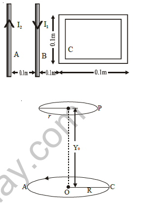
[Figure: A circular coil ACD of radius R lying in the plane of the paper with its centre O, and a small ring P of radius r on the vertical axis at a height y0 above O, shown falling downward]
Answer:
1. Field on the axis of the coil at height y: B = \( \frac{μ_0 n i R^{2}}{2(R^{2} + y^{2})^{3/2}} \).
2. The ring is small, so the flux through it is φ = B π r².
3. e.m.f. = \( \frac{dφ}{dt} \) = π r² \( \frac{dB}{dy} \) \( \frac{dy}{dt} \), with \( \frac{dy}{dt} \) = v (speed of the ring).
4. \( \frac{dB}{dy} \) = -\( \frac{3 μ_0 n i R^{2} y}{2(R^{2} + y^{2})^{5/2}} \).
5. Magnitude of e.m.f. at y = y0 = \( \frac{3 μ_0 π n i R^{2} r^{2} y_0 v}{2(R^{2} + y_0^{2})^{5/2}} \).
Teacher's Note:
a) Differentiate the on-axis field with respect to height and multiply by the speed, since the flux changes only because the ring moves.
b) The e.m.f. is zero at y = 0 and falls to zero at large distances.
7. A metal rod OA of mass m can rotate about a horizontal axis O, sliding along a circular conducting ring of radius r as shown in figure. This arrangement is located in a uniform magnetic field of induction B, directed perpendicular to the plane of the ring. The axis O and the rim of ring are connected to a source of E.M.F. to form a noninductive closed circuit of resistance R. Neglecting friction and ring resistance, find an expression for the E. M. F. in terms of time t, so that the rod rotates with constant angular velocity.
[Figure: A circular conducting ring of radius r with centre O. A metal rod OA rotates about O, making an angle ωt with the vertical line through O, and its end A slides on the ring. A source of e.m.f. E is connected between the axis O and the rim of the ring; the magnetic field is perpendicular to the plane of the ring]
Answer:
1. The rod rotating with angular velocity ω has a motional e.m.f. ε = \( \frac{1}{2} \) B ω r², which opposes the source e.m.f. E.
2. Let I be the current. The magnetic force B I r acts at the middle of the rod, so the magnetic torque = B I r × \( \frac{r}{2} \) = \( \frac{1}{2} \) B I r².
3. At time t the rod makes an angle ωt with the vertical, so the torque of its weight about O = m g \( \frac{r}{2} \) sin ωt.
4. For constant ω the torques balance: \( \frac{1}{2} \) B I r² = \( \frac{1}{2} \) m g r sin ωt, so I = \( \frac{m g sin ωt}{B r} \).
5. For the circuit, E - ε = I R, so E = \( \frac{1}{2} \) B ω r² + \( \frac{m g R sin ωt}{B r} \).
6. E = \( \frac{1}{2rB} \) [r³B²ω + 2mgR sin ωt].
Teacher's Note:
a) Constant angular velocity means the net torque on the rod is zero at every instant.
b) The source e.m.f. must supply both the current for the magnetic torque and the voltage that balances the back e.m.f.
8. The rectangular wire-frame, shown in figure, has a width d, mass m, resistance R and a large length. A uniform magnetic field B exists to the left of the frame. A constant force F starts pushing the frame into the magnetic field at t = 0.
(a) Find the acceleration of the frame when its speed has increased to v.
(b) Show that after some time the frame will move with a constant velocity till the whole frame enters the magnetic field. Find the velocity v0.
(c) Show that the velocity at time t is given by v = v0 (i - e-Ft/mV0).
[Figure: A rectangular wire frame of width d and large length, whose right end is pushed to the left by a constant force F. A region of uniform magnetic field B (shown by crosses) lies to the left of the frame, and the frame enters it from the right]
Answer:
1. (a) The side of width d inside the field gives e.m.f. = B d v, so the current I = \( \frac{B d v}{R} \).
2. The magnetic force opposing the motion = B I d = \( \frac{B^{2} d^{2} v}{R} \).
3. Acceleration a = \( \frac{F - B^{2} d^{2} v / R}{m} \) = \( \frac{RF - B^{2} d^{2} v}{m R} \).
4. (b) As v increases, the opposing force increases and the acceleration falls. When a = 0 the velocity becomes constant, so F = \( \frac{B^{2} d^{2} v_0}{R} \).
5. v0 = \( \frac{R F}{B^{2} d^{2}} \). This speed is kept until the whole frame is inside the field.
6. (c) The equation of motion is m \( \frac{dv}{dt} \) = F - \( \frac{F}{v_0} \) v = F(1 - \( \frac{v}{v_0} \)).
7. Separating variables: \( \frac{dv}{v_0 - v} \) = \( \frac{F}{m v_0} \) dt. Integrating from v = 0 at t = 0: - ln(1 - \( \frac{v}{v_0} \)) = \( \frac{F t}{m v_0} \).
8. Hence v = v0(1 - e-Ft/m v0). The symbol "i" printed in the question stands for 1.
Teacher's Note:
a) Only the leading side of width d cuts the field while the frame is entering.
b) The approach to the terminal velocity is exponential with time constant m v0/F.
9. A thin wire ring of radius a and resistance r is located inside a long solenoid so that their axes coincide. The length of the solenoid is equal to l and its cross-section radius is b. The solenoid is connected to a source of constant voltage V. The total resistance of the circuit is equal to R. Assuming the inductance of the ring to be negligible, find the maximum value of the radial force acting per unit length of the ring.
[Figure: A long solenoid of length l and cross-section radius b with a thin ring of radius a placed coaxially inside it; the solenoid is connected in a closed circuit to a battery of constant voltage V]
Answer:
1. Let the solenoid have N turns. Its inductance L = \( \frac{μ_0 N^{2} π b^{2}}{l} \) and its current grows as I = I0(1 - e-t/τ), with I0 = \( \frac{V}{R} \) and τ = \( \frac{L}{R} \).
2. Field in the solenoid B = \( \frac{μ_0 N I}{l} \). Flux through the ring = B π a².
3. e.m.f. in the ring = \( \frac{μ_0 N π a^{2}}{l} \) \( \frac{dI}{dt} \), so the ring current i = \( \frac{μ_0 N π a^{2}}{l r} \) \( \frac{dI}{dt} \).
4. Radial force per unit length = B i = \( \frac{μ_0^{2} N^{2} π a^{2}}{l^{2} r} \) I \( \frac{dI}{dt} \).
5. I \( \frac{dI}{dt} \) = \( \frac{I_0^{2}}{τ} \) (1 - x) x with x = e-t/τ, whose maximum value (at x = \( \frac{1}{2} \)) is \( \frac{I_0^{2}}{4τ} \).
6. Substituting I0 = V/R and τ = \( \frac{μ_0 N^{2} π b^{2}}{l R} \), the factor N cancels.
7. Maximum force per unit length = \( \frac{μ_0 a^{2} V^{2}}{4 R r l b^{2}} \).
Teacher's Note:
a) The force per unit length on a current element is the field times the current, directed radially.
b) The maximum of x(1 - x) occurs at x = 1/2, that is at t = τ ln 2.
c) The printed key has no ring resistance r and has μ0 squared, so it cannot be dimensionally correct; the result above has the unit of N/m.
10. A rod of length 2 a is free to rotate in a vertical plane, about a horizontal axis O passing through its midpoint. A long straight, horizontal wire is in the same plane and is carrying a constant current i as shown in figure. At t = 0, the rod is horizontal and starts rotating with constant angular velocity ω. Calculate e.m.f. induced in rod as a function of time.
[Figure: A long straight horizontal wire carrying a current i towards the right, at a distance d above a horizontal rod of length 2a. The rod has its midpoint O below the wire and rotates about O in the vertical plane with angular velocity ω]
Answer:
1. At time t the rod makes an angle θ = ωt with the horizontal. Take an element at distance s from O (s from -a to +a); its height above O is s sin θ, so its distance from the wire is d - s sin θ.
2. Field of the wire at the element, B = \( \frac{μ_0 i}{2π (d - s \sin θ)} \), and the speed of the element = ω s, perpendicular to the rod.
3. e.m.f. = ∫ B (ω s) ds = \( \frac{μ_0 i ω}{2π} \) ∫ \( \frac{s ds}{d - s \sin θ} \), integrated from -a to a.
4. ∫ \( \frac{s ds}{d - s \sin θ} \) = -\( \frac{2a}{\sin θ} \) + \( \frac{d}{\sin^{2} θ} \) ln \( \frac{d + a \sin θ}{d - a \sin θ} \).
5. e.m.f. = \( \frac{μ_0 i ω}{2π \sin^{2} ωt} \) [ -2a sin ωt + d ln \( \frac{d + a \sin ωt}{d - a \sin ωt} \) ].
Teacher's Note:
a) Different parts of the rod are at different distances from the wire, so the field must be integrated along the rod.
b) Check: for small a the bracket tends to zero, as expected for a uniform field.
11. Two long parallel rails separated by a distance l are connected by a movable connector of mass m. Terminals of the rails are connected across a resistor of resistance R and a capacitor of capacitance C as shown in figure. A uniform magnetic field B perpendicular to the plane of the rails is switched on and the connector is dragged by a constant force F. Find terminal velocity of the connector. Neglect the friction between the rails and the connector and resistance of connector.
[Figure: Two long parallel horizontal rails of separation l. At the left end they are joined by a resistor R and at the right end by a capacitor C. A movable connector of mass m between the rails is pulled to the left by a constant force F; the magnetic field B is perpendicular to the plane of the rails]
Answer:
1. When the connector moves with speed v, the e.m.f. = B l v appears across both the resistor and the capacitor.
2. Current in R, IR = \( \frac{B l v}{R} \) and the capacitor current IC = C \( \frac{d(B l v)}{dt} \) = C B l a.
3. The magnetic force on the connector = B l (IR + IC) = \( \frac{B^{2} l^{2} v}{R} \) + C B² l² a.
4. Equation of motion: F - \( \frac{B^{2} l^{2} v}{R} \) - C B² l² a = m a.
5. At terminal velocity a = 0, and the capacitor current is zero, so F = \( \frac{B^{2} l^{2} v}{R} \).
6. v = \( \frac{F R}{B^{2} l^{2}} \).
Teacher's Note:
a) At terminal velocity the capacitor is fully charged and carries no current; only the resistor takes current.
b) The capacitor changes how fast the terminal velocity is approached but not its value.
12. A thin non-conducting ring of mass m and radius a carrying a charge q can rotate freely about its own axis that is vertical. At the initial moment, the ring was at rest and no magnetic field was present. At instant t = 0, a uniform magnetic field is switched on which is vertically downwards and increases with time according to the law B = B0t. Neglecting magnetism induced due to rotational motion of the ring, calculate
(a) angular acceleration of the ring
(b) power developed by the forces acting on the ring as function of time
Answer:
1. (a) The changing flux sets up an electric field around the ring: E (2πa) = π a² \( \frac{dB}{dt} \) = π a² B0, so E = \( \frac{a B_0}{2} \).
2. Torque on the ring = q E a = \( \frac{q a^{2} B_0}{2} \).
3. Moment of inertia of the ring = m a², so the angular acceleration α = \( \frac{q a^{2} B_0 / 2}{m a^{2}} \) = \( \frac{q B_0}{2m} \).
4. (b) Angular velocity at time t, ω = α t = \( \frac{q B_0 t}{2m} \).
5. Power = torque × ω = \( \frac{q a^{2} B_0}{2} \) × \( \frac{q B_0 t}{2m} \) = \( \frac{q^{2} B_0^{2} a^{2} t}{4m} \).
Teacher's Note:
a) A changing magnetic field produces a circular electric field even without any conductor; this field acts on the charge of the ring.
b) The magnetic force does no work; the power comes entirely from the induced electric force.
13. Consider the circuit shown in the figure. What is the current through the battery
(a) just after the switch is closed
(b) long after the switch has been closed?
[Figure: An 18 V battery with a switch S connected across three parallel branches: the first branch has a 2 mH inductor in series with a 9 Ω resistor, the second branch has a single 9 Ω resistor, and the third branch has a 9 Ω resistor in series with a 2 mH inductor]
Answer: (a) 2 A; (b) 6 A
1. The circuit has three parallel branches across the 18 V battery: a 2 mH inductor in series with 9 Ω, a single 9 Ω resistor, and a 9 Ω resistor in series with a 2 mH inductor.
2. (a) Just after the switch is closed, the inductors oppose any change of current and carry no current, so only the middle 9 Ω resistor conducts: I = \( \frac{18}{9} \) = 2 A.
3. (b) Long after, the inductors act as plain wires, so three 9 Ω resistors are in parallel: R = \( \frac{9}{3} \) = 3 Ω.
4. I = \( \frac{18}{3} \) = 6 A.
Teacher's Note:
a) An inductor behaves as an open circuit at t = 0 and as a short circuit at t = ∞.
b) Do not use the inductance value in either case; it matters only for the time taken to reach the steady state.
14. A coil ACD of radius R and number of turns n carries a current i amp. and is placed in the plane of paper. A small conducting ring P of radius r is placed at a distance y0 from the centre of and above the coild ACD. Calculate the induced emf produced in the ring when the ring is allowed to full freely. Express induced emf in terms of speed of the ring and its distance w.r.t. coil.
[Figure: A circular coil ACD of radius R lying in the plane of the paper with its centre O, and a small ring P of radius r on the vertical axis at a height y0 above O, shown falling downward]
Answer:
1. Field on the axis of the coil at a distance y: B = \( \frac{μ_0 n i R^{2}}{2(R^{2} + y^{2})^{3/2}} \), and the flux through the small ring is φ = B π r².
2. e.m.f. = \( \frac{dφ}{dt} \) = π r² \( \frac{dB}{dy} \) \( \frac{dy}{dt} \), where \( \frac{dy}{dt} \) = v.
3. \( \frac{dB}{dy} \) = -\( \frac{3 μ_0 n i R^{2} y}{2(R^{2} + y^{2})^{5/2}} \).
4. Magnitude of e.m.f. = \( \frac{3 μ_0 π n i R^{2} r^{2} y v}{2(R^{2} + y^{2})^{5/2}} \), where y is the distance of the ring from the centre of the coil at that instant and v is its speed.
Teacher's Note:
a) This is the same set-up as the previous problem with the distance y written as a variable.
b) The printed key leaves out the number of turns n and shows a factor 4 instead of 2 in the denominator; the formula above follows from the on-axis field of an n-turn coil.
15. In the circuit shown in adjoining figure, E = 10 V, R1 = 1 Ω, R2 = 2 Ω, R3 = 3 Ω and L = 2H. Calculate the values of currents i1, i2 and i3.
(a) immediately after switch S is closed
(b) sufficient time after the switch S is closed
(c) immediately after opening the switch
(d) sufficient time after opening the switch
[Figure: A battery E with a switch S in series with R1 carrying current i1. At the junction after R1, R2 carries current i2 downward and a second branch containing R3 in series with the inductor L carries current i3 to the right]
Answer: (a) i1 = i2 = 3.3 A, i3 = 0; (b) i1 = 4.5 A, i2 = 2.7 A, i3 = 1.8 A; (c) i1 = 0, i2 = i3 = 1.8 A; (d) all zero
1. R1 is in the main line; below the junction R2 carries i2 and the branch with R3 and the inductor L carries i3.
2. (a) Immediately after closing, the inductor carries no current: i3 = 0 and i1 = i2 = \( \frac{10}{1 + 2} \) = 3.3 A.
3. (b) After a long time, L acts as a plain wire, so R2 and R3 are in parallel: \( \frac{2 \times 3}{2 + 3} \) = 1.2 Ω and the total resistance = 2.2 Ω.
4. i1 = \( \frac{10}{2.2} \) = 4.5 A. The voltage across the parallel pair = 4.5 × 1.2 = 5.45 V, so i2 = \( \frac{5.45}{2} \) = 2.7 A and i3 = \( \frac{5.45}{3} \) = 1.8 A.
5. (c) Immediately after opening the switch, i1 = 0. The inductor current 1.8 A continues through R3 and now returns through R2, so i3 = 1.8 A and i2 = 1.8 A (in the direction opposite to its earlier direction).
6. (d) A long time after opening, the stored energy is dissipated and i1 = i2 = i3 = 0.
Teacher's Note:
a) The current in an inductor cannot change instantly, so after opening the switch the inductor current simply continues in the same direction.
b) The current in R2 reverses on opening because it now carries the inductor current in the loop of R2, R3 and L.
16. A jumper of length l = 1 m and resistance r = 1 Ω moves along two conducting smooth guides of negligible resistance with uniform speed v = 5 m/s. The ends of the guides are joined by resistances R1 = 6 Ω and R2 = 4 Ω. There is a uniform magnetic induction B = 0.3 T perpendicular into the plane of the loop. Determine:
(a) the current through the jumper,
(b) The current through R1 and R2,
(c) The mechanical power needed for the motion of the jumper.
[Figure: Two horizontal conducting guides with a movable jumper between them, moving to the right with speed v. The left ends of the guides are joined by R1 and the right ends by R2; the magnetic field B points into the plane of the loop, shown by crosses]
Answer: (a) 0.44 A; (b) 0.176 A in R1 and 0.264 A in R2; (c) 0.66 W
1. e.m.f. of the jumper = B l v = 0.3 × 1 × 5 = 1.5 V.
2. R1 and R2 are in parallel: \( \frac{6 \times 4}{6 + 4} \) = 2.4 Ω, so the total resistance = 2.4 + 1 = 3.4 Ω.
3. (a) Current through the jumper = \( \frac{1.5}{3.4} \) = 0.44 A.
4. (b) Voltage across the resistors = 0.441 × 2.4 = 1.06 V, so IR1 = \( \frac{1.06}{6} \) = 0.176 A and IR2 = \( \frac{1.06}{4} \) = 0.264 A.
5. (c) Mechanical power = F v = B I l v = 0.3 × 0.441 × 1 × 5 = 0.66 W.
Teacher's Note:
a) The jumper is the source of e.m.f. with internal resistance 1 Ω, and the two resistors share the current in the inverse ratio of resistance.
b) The mechanical power equals the total electrical power: 1.5 × 0.441 = 0.66 W.
17. A conducting rod of mass m slides freely along the two parallel conducting wires as shown in the figure. The wires are placed a distance b apart. The wires are electrically connected via a resistor R on one side and by the sliding rod on the other side. The whole system is embedded in a uniform magnetic field B0, which is perpendicularly directed into the page. At the moment t = 0 the rod is given an initial velocity v0 x̂ along the wires.
(a) compute the electric current in the resistor R as a function of the instantaneous velocity of the rod v(t)
(b) compute the rod's displacement x(t) and velocity v(t).
(c) compute the change in the kinetic energy of the rod (relative to its initial value) at the moment t = τ = \( \frac{mR}{B^{2} b^{2}} \)
(d) what is the physical reason for the dissipation of the kinetic energy of the rod?
[Figure: Two parallel horizontal conducting wires a distance b apart, joined on the right side by a resistor R and on the left side by a sliding rod of mass m moving to the left with initial velocity v0. A uniform magnetic field B0 is directed into the page (shown by crosses). The x-axis points to the left and the y-axis points downward]
Answer:
1. (a) The e.m.f. = B0 b v(t), so I(t) = \( \frac{B_0 b v(t)}{R} \).
2. (b) The magnetic force on the rod = B0 I b = \( \frac{B_0^{2} b^{2} v}{R} \) opposes the motion: m \( \frac{dv}{dt} \) = -\( \frac{B_0^{2} b^{2}}{R} \) v.
3. With τ = \( \frac{m R}{B_0^{2} b^{2}} \), \( \frac{dv}{v} \) = -\( \frac{dt}{τ} \), so v(t) = v0 e-t/τ.
4. Displacement x(t) = ∫ v dt = v0 τ (1 - e-t/τ).
5. (c) At t = τ, v = v0 e-1, so the final kinetic energy = \( \frac{1}{2} \) m v0² e-2.
6. Change in kinetic energy = \( \frac{1}{2} \) m v0² e-2 - \( \frac{1}{2} \) m v0² = -\( \frac{m v_0^{2}}{2} \) (1 - e-2).
7. (d) The lost kinetic energy is converted into heat in the resistor R (Joule heating of the induced current).
Teacher's Note:
a) The motion is a decaying exponential because the retarding force is proportional to the velocity.
b) The total distance the rod travels is v0 τ.
c) The heat produced in R over the whole motion equals the initial kinetic energy \( \frac{1}{2} \) m v0².
18. A coil of inductance 1 henry and resistance 10 Ω is connected to a resistanceless battery of emf 50 V at time t = 0. Calculate the ratio of the rate at which magnetic energy is stored in the coil to the rate at which energy is supplied by the battery at t = 0.1 s.
Answer: Ratio ≈ 0.37
1. Time constant τ = \( \frac{L}{R} \) = \( \frac{1}{10} \) = 0.1 s, and the current I = 5(1 - e-t/τ).
2. At t = 0.1 s: I = 5(1 - e-1) = 3.16 A and \( \frac{dI}{dt} \) = 50 e-1 = 18.4 A/s.
3. Rate of storage of magnetic energy = L I \( \frac{dI}{dt} \) = 1 × 3.16 × 18.4 ≈ 58.1 W.
4. Rate at which the battery supplies energy = E I = 50 × 3.16 ≈ 158 W.
5. Ratio = \( \frac{58.1}{158} \) = e-1 ≈ 0.37.
Teacher's Note:
a) Total power from the battery = heat in the resistor + rate of storage in the inductor.
b) The ratio simplifies to e-t/τ, which is the fraction of the battery power that still goes into the field.
19. A small conducting loop of mass m, radius r and resistance R is released from rest along a smooth inclined plane such that the plane of the loop is perpendicular to a magnetic field which varies along x-axis as B = B0 (1 + ax). Here B0 and a are constants. Find the speed of the ring at time t.
[Figure: A smooth inclined plane at an angle θ to the horizontal x-axis, with a small conducting loop on the incline. A magnetic field B, directed into the plane of the figure (shown by a cross inside a circle), varies along the x-axis]
Answer:
1. When the loop moves down the incline with speed v, its x-coordinate changes at the rate \( \frac{dx}{dt} \) = v cos θ.
2. Flux = B π r², so e.m.f. = π r² \( \frac{dB}{dt} \) = π r² B0 a v cos θ.
3. Current I = \( \frac{π r^{2} B_0 a v \cos θ}{R} \).
4. Power dissipated = \( \frac{(emf)^{2}}{R} \) = Fr v, where Fr is the retarding force along the incline, so Fr = \( \frac{π^{2} r^{4} B_0^{2} a^{2} \cos^{2} θ}{R} \) v.
5. Equation of motion along the incline: m \( \frac{dv}{dt} \) = m g sin θ - m k v, with k = \( \frac{π^{2} r^{4} B_0^{2} a^{2} \cos^{2} θ}{m R} \).
6. Integrating with v = 0 at t = 0: v = \( \frac{g \sin θ}{k} \) (1 - e-kt).
Teacher's Note:
a) The loop feels a retarding force proportional to its speed, so its speed approaches the terminal value g sin θ / k exponentially.
b) Find the force from the energy balance instead of finding the force on each side of the loop.
20. A conducting rod AC of mass m free to rotate in a horizontal plane about one end A over a semicircular conducting ring of radius a is joined with an external resistance R as shown in the figure. The resistance of the rod is r. The rod is given an initial angular velocity ω0. A uniform magnetic field of magnitude B exists perpendicular to the plane of semicircular loop. Find the current in the circuit at angle θ.
[Figure: A semicircular conducting ring of radius a with centre A, joined to an external resistance R by wires. A conducting rod AC rotates about the end A in the horizontal plane, with its other end C sliding on the ring. The rod starts from the vertical position with angular velocity ω0 and has turned through an angle θ; the magnetic field B is perpendicular to the plane (into the page)]
Answer:
1. When the rod rotates with angular velocity ω, the e.m.f. = \( \frac{1}{2} \) B ω a² and the current I = \( \frac{B ω a^{2}}{2(R + r)} \).
2. Magnetic force on the rod = B I a acting at its middle, so the torque = B I a × \( \frac{a}{2} \) = \( \frac{B^{2} a^{4} ω}{4(R + r)} \), opposing the rotation.
3. Moment of inertia of the rod about A = \( \frac{m a^{2}}{3} \), so \( \frac{dω}{dt} \) = -\( \frac{3 B^{2} a^{2} ω}{4 m (R + r)} \).
4. Writing \( \frac{dω}{dt} \) = ω \( \frac{dω}{dθ} \): \( \frac{dω}{dθ} \) = -\( \frac{3 B^{2} a^{2}}{4 m (R + r)} \).
5. Integrating from θ = 0: ω = ω0 - \( \frac{3 B^{2} a^{2} θ}{4 m (R + r)} \).
6. Current at angle θ: i = \( \frac{B a^{2}}{2(R + r)} \) [ω0 - \( \frac{3}{4} \) \( \frac{B^{2} a^{2} θ}{m (R + r)} \)].
Teacher's Note:
a) Use ω dω/dθ in place of dω/dt to get the angular velocity directly as a function of angle.
b) The moment of inertia of a rod about its end is m a²/3, and the magnetic force acts at the midpoint.
21. A battery of 150 V and negligible internal resistance is connected to an inductor in a circuit containing three resistors and a switch as shown in the circuit. Find the values of currents i1, i2 and i3
(a) soon after the switch is closed.
(b) long after the switch is closed.
(c) immediately after the switch is opened.
(d) long after the switch is opened.
[Figure: A 150 V battery and a switch in the top wire from A to B. A vertical wire from A goes down through a 20 Ω resistor (current i1) to the junction F, then through a 60 Ω resistor (current i3, downward) to the point E. From F a 40 Ω resistor (current i2, towards the right) leads to the point C on the right-hand vertical wire BCD. From E a 3 H inductor leads to the point D on the right-hand wire]
Answer: (a) i1 = i2 = 2.5 A, i3 = 0; (b) i1 = 3.4 A, i2 = 2.05 A, i3 = 1.36 A; (c) i1 = 0, i3 = 1.36 A, i2 = -1.36 A; (d) i1 = i2 = i3 = 0
1. The battery and switch join A and B, and the right-hand wire B-C-D is a plain wire. From A, the 20 Ω resistor leads to F; from F, the 40 Ω resistor leads to C and the 60 Ω resistor in series with the 3 H inductor leads to D. The currents are i1 in 20 Ω, i2 in 40 Ω and i3 in 60 Ω.
2. (a) Soon after closing, the inductor carries no current: i3 = 0 and i1 = i2 = \( \frac{150}{20 + 40} \) = 2.5 A.
3. (b) Long after closing, the inductor is a plain wire, so 40 Ω and 60 Ω are in parallel: \( \frac{40 \times 60}{100} \) = 24 Ω and the total resistance = 44 Ω.
4. i1 = \( \frac{150}{44} \) = 3.4 A. The voltage across the parallel part = 3.41 × 24 = 81.8 V, so i2 = \( \frac{81.8}{40} \) = 2.05 A and i3 = \( \frac{81.8}{60} \) = 1.36 A.
5. (c) Immediately after opening, i1 = 0. The inductor keeps its current of 1.36 A, which flows through 60 Ω and returns through 40 Ω: i3 = 1.36 A and i2 = -1.36 A (the current in the 40 Ω resistor reverses).
6. (d) Long after opening, all the stored energy is dissipated: i1 = i2 = i3 = 0.
Teacher's Note:
a) After the switch is opened, the 20 Ω resistor is out of the loop; the inductor, 60 Ω and 40 Ω form the only closed loop.
b) Since i1 = 0, the junction rule at F gives i2 = -i3; the printed key value i2 = i3 = -1.8 A for part (c) cannot satisfy this rule, and the inductor current just before opening is 1.36 A.
Free study material for Physics
Free CBSE Study Guides: Class 12 Physics Chapter 06 Electromagnetic Induction
Comprehensive Study Resources for Chapter 06 Electromagnetic Induction
Access comprehensive study material for Chapter 06 Electromagnetic Induction, including revision notes, concept maps, and high-probability questions. These resources are designed in alignment with the latest 2026 CBSE syllabus for Class 12 Physics to support effective exam preparation.
Understanding Marking Schemes
Designed around the official curriculum, these study guides guarantee standard compliance. Reviewing step-by-step solutions clarifies complex sub-topics within Chapter 06 Electromagnetic Induction and demystifies standard marking schemes for Physics evaluations.
Complete Revision for Physics
Maximize your grade potential by utilizing Class 12 Physics practice papers in tandem with these structured notes. All printable assignments and interactive mock tests on our platform are updated for the 2026 session and available free of charge.
FAQs
Our advanced study package for Chapter 06 Electromagnetic Induction includes detailed concepts, diagrams, Mind Maps, and explanation of complex topics to ensure Class 12 students learn as per syllabus for 2026 exams.
The Mind Maps provided for Chapter 06 Electromagnetic Induction act as visual anchors which will help faster recall during high-pressure exams.
Yes, teachers use our Class 12 Physics resources for lesson planning as they are in simple language and have lot of solved examples.
Yes, You can download the complete, mobile-friendly PDF of the Physics Chapter 06 Electromagnetic Induction advanced resources for free.
Yes, our subject matter experts have updated the Chapter 06 Electromagnetic Induction material to align with the rationalized NCERT textbooks and have removed deleted topics and added new competency-based questions.