

Advanced Study Material for Class 12 Physics: Chapter 01 Electric Charges and Fields
Review targeted academic resources with the CBSE Class 12 Physics Electrical Instrument Solved Examples.. Built according to official CBSE standards for the 2026-27 term, these downloadable Class 12 Physics study materials support effective daily practice and deeper conceptual understanding for Chapter 01 Electric Charges and Fields.
Practice Class 12 Physics Resources: Chapter 01 Electric Charges and Fields
Access the complete useful resource PDF for Class 12 Physics below. Regular practice with these targeted academic notes builds familiarity with complex topics and helps secure higher marks in final school evaluations.
This Class 12 Physics set of solved examples on Electrical Instruments covers the voltmeter and ammeter errors, galvanometer shunts and series resistances, the potentiometer and its balancing length, potential gradient, comparison of emf, and internal resistance of a cell, with each example worked out step by step.
SOLVED EXAMPLES: ELECTRICAL INSTRUMENTS
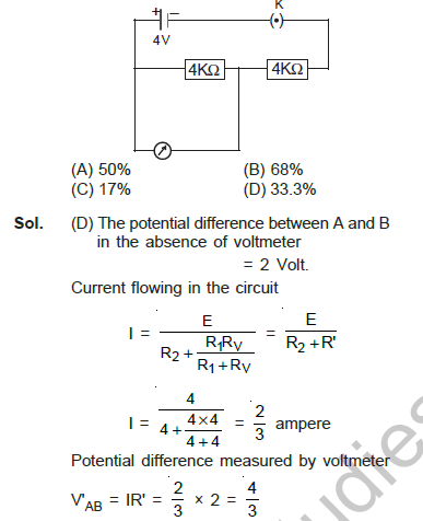
Ex.1 In the circuit shown below fig. if the resistance of voltmeter is 4KΩ, then the error in the reading of voltmeter will be-
[Figure: 4 V cell in a circuit with two 4 kΩ resistors in series, points A and B across one of them, and a voltmeter of resistance 4 kΩ connected across AB.]
(A) 50%
(B) 68%
(C) 17%
(D) 33.3%

Answer: (D) 33.3%
1. In the absence of the voltmeter, the potential difference between A and B is 2 V.
2. With the voltmeter in parallel with the 4 kΩ resistor, the effective resistance is 2 kΩ, so the current is I = 4 / (4 + 4 × 4 / (4 + 4)) = 4 / 6 = 2/3 A.
3. The voltmeter reads V′ = (2/3) × 2 = 4/3 V.
4. Error = 2 - 4/3 = 2/3 V. For a 2 V difference, this is (2/3)/2 = 33.3%.
The error in voltmeter reading for 2 volt p.d. = 2/3 volt.
The error in voltmeter reading for 1 volt p.d. = (2/3) × (1/2) = 1/3 volt.
The error in voltmeter reading for 100 volt p.d. = 100/3 = 33.3% volt.
Teacher's Note:
a) The error is measured as a percentage of the true potential difference.
b) Common mistake: comparing the error with the voltmeter resistance rather than with the true potential difference.
c) The error is computed on the true potential difference of 2 V, not on the voltmeter resistance.
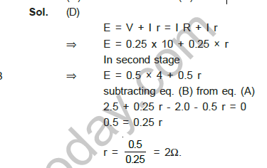
Ex.2 When a Laclanche cell is connected to a 10Ω resistance then a current of 0.25 ampere flows in the circuit. If the resistance is reduced to 4Ω then current becomes 0.5 ampere. The internal resistance of galvanometer will be-
(A) 1.5 ohm
(B) 0.5 ohm
(C) 1 ohm
(D) 2 ohm
Answer: (D) 2 ohm
1. E = I₁(R₁ + r) = 0.25 (10 + r).
2. E = I₂(R₂ + r) = 0.5 (4 + r).
3. Equating: 2.5 + 0.25r = 2 + 0.5r, so 0.5 = 0.25r.
4. r = 2 Ω.
Teacher's Note:
a) Two equations for E and r are obtained from the two states of the circuit.
b) Common mistake: ignoring the internal resistance of the cell in the second case.
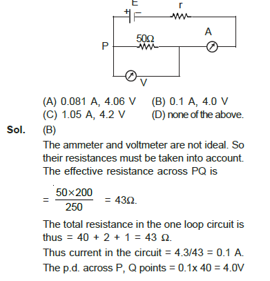
Ex.3 The emf E and internal resistance r of the cell shown in fig. are 4.3 V and 1 ohm respectively. The resistances of ammeter A and voltmeter V are 2Ω and 200Ω respectively. Then, the readings in the ammeter and voltmeter are-
[Figure: cell of emf E and internal resistance r, ammeter A in series, a 50 Ω resistor between P and Q, and a voltmeter V connected across PQ.]
(A) 0.081 A, 4.06 V
(B) 0.1 A, 4.0 V
(C) 1.05 A, 4.2 V
(D) none of the above.
Answer: (B) 0.1 A, 4.0 V
1. The ammeter and voltmeter are not ideal, so their resistances are included.
2. Effective resistance across PQ = (50 × 200)/(50 + 200) = 40 Ω.
3. Total resistance = 40 + 2 + 1 = 43 Ω.
4. Current I = 4.3 / 43 = 0.1 A.
5. Potential difference across PQ = 0.1 × 40 = 4.0 V.
Teacher's Note:
a) Ammeter resistance is added in series, while the voltmeter resistance is added in parallel with the 50 Ω resistor.
b) Common mistake: treating the meters as ideal and getting 4.3 A.
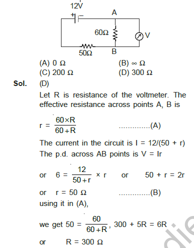
Ex.4 The voltmeter shown in fig, reads 6V across the 60Ω resistor. Then the resistance of the voltmeter is-
[Figure: 12 V cell with a 50 Ω resistor in series, a 60 Ω resistor, and a voltmeter V across the 60 Ω resistor between points A and B.]
(A) 0 Ω
(B) ∞ Ω
(C) 200 Ω
(D) 300 Ω
Answer: (D) 300 Ω
1. Let R be the resistance of the voltmeter, which is in parallel with 60 Ω, so r = 60R / (60 + R).
2. The current is I = 12 / (50 + r), and the voltage across AB is V = Ir = 6 V.
3. 12r / (50 + r) = 6 gives 2r = 50 + r, so r = 50 Ω.
4. 60R / (60 + R) = 50 gives 60R = 3000 + 50R, so R = 300 Ω.
Teacher's Note:
a) The voltmeter reads a fraction of the source voltage, so its resistance must be large but finite.
b) Common mistake: taking the voltmeter resistance as infinite, which would give 12 V across the 60 Ω.
c) Check the answer by putting R = 300 Ω back: 60 × 300 / 360 = 50 Ω, which gives the correct 6 V.
Ex.5 If only one hundredth part of total current flowing in the circuit is to be passed through a galvanometer of resistance GΩ, Then the value of shunt resistance required will be-
(A) G/10
(B) G/100
(C) G/99
(D) G/999
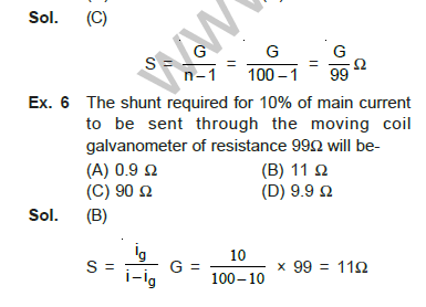
Answer: (C) G/99
1. Let the shunt be S and the galvanometer carry 1/100 of the current.
2. The shunt carries 99/100 of the current, so S = G/(n - 1) with n = 100.
3. S = G/99.
Teacher's Note:
a) For a shunt, S = G/(n - 1), where n is the ratio of total current to galvanometer current.
b) Common mistake: writing G/100, which gives the wrong ratio.
Ex.6 The shunt required for 10% of main current to be sent through the moving coil galvanometer of resistance 99Ω will be-
(A) 0.9 Ω
(B) 11 Ω
(C) 90 Ω
(D) 9.9 Ω
Answer: (B) 11 Ω
1. Galvanometer current i_g is 10% of the main current i, so the shunt carries 90% of i.
2. S = i_g G / (i - i_g) = (10 / 90) × 99 = 11 Ω.
Teacher's Note:
a) The shunt is in parallel with the galvanometer, so it takes the larger part of the current.
b) Common mistake: using i_g / i instead of i_g / (i - i_g).
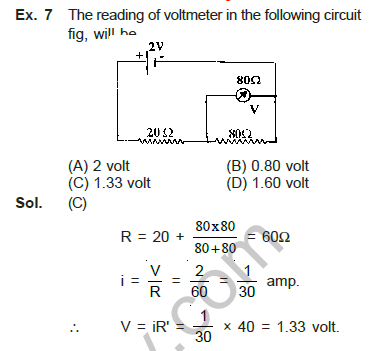
Ex.7 The reading of voltmeter in the following circuit fig, will be-
[Figure: 2 V source with a 20 Ω series resistor, a parallel pair of 80 Ω resistors, and a voltmeter across the 40 Ω section of the parallel pair.]
(A) 2 volt
(B) 0.80 volt
(C) 1.33 volt
(D) 1.60 volt
Answer: (C) 1.33 volt
1. Resistance of the parallel combination in one branch = 80 × 80 / (80 + 80) = 40 Ω, so the total resistance R = 20 + 40 = 60 Ω.
2. Current i = V / R = 2 / 60 = 1/30 A.
3. Voltmeter reading V′ = i × 40 = (1/30) × 40 = 1.33 V.
Teacher's Note:
a) Find the equivalent resistance of the circuit before finding the current.
b) Common mistake: forgetting that the 40 Ω branch carries the current to the voltmeter.
Ex.8 In the calibration of ammeter experiment, a standard cell of e.m.f. 1.1 volt gets balanced at 7.70 m of potentiometer wire. If the potential difference across 1Ω resistance gets balanced at 1.75m, then the current indicated by ammeter is 2/10A. The error in the reading of ammeter will be-
(A) 0.05 A
(B) -0.05 A
(C) zero
(D) 0.01 A
Answer: (B) -0.05 A
1. Potential gradient φ = E_s / l_s = 1.1 / 7.7 V/m.
2. True current I′ = φ × l = (1.1 / 7.7) × 1.75 = 0.25 A.
3. Indicated current I = 2/10 = 0.2 A.
4. Error = I - I′ = 0.2 - 0.25 = -0.05 A.
Teacher's Note:
a) A negative error means the ammeter reads less than the true current.
b) Common mistake: reversing the subtraction, which changes the sign.
c) Ammeter error is the indicated current minus the true current, so a negative value means under-reading.
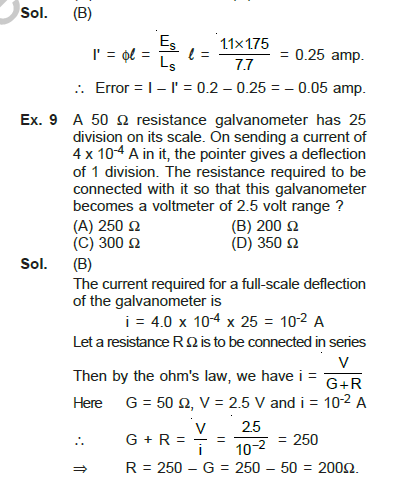
Ex.9 A 50 Ω resistance galvanometer has 25 division on its scale. On sending a current of 4 x 10⁻⁴ A in it, the pointer gives a deflection of 1 division. The resistance required to be connected with it so that this galvanometer becomes a voltmeter of 2.5 volt range ?
(A) 250 Ω
(B) 200 Ω
(C) 300 Ω
(D) 350 Ω
Answer: (B) 200 Ω
1. Full scale current i = 4 × 10⁻⁴ × 25 = 10⁻² A.
2. Required total resistance = V / i = 2.5 / 10⁻² = 250 Ω.
3. Series resistance R = 250 - 50 = 200 Ω.
Teacher's Note:
a) A voltmeter is made by adding a high series resistance to the galvanometer.
b) Common mistake: giving the answer as the total resistance rather than the added series resistance.
Ex.10 A voltmeter can measure upto 25 volt and its resistance is 1000 Ω. The resistance required to add with voltmeter to measure upto 250 volt will be-
(A) 9000 Ω
(B) 1000 Ω
(C) 2500 Ω
(D) 900 Ω
Answer: (A) 9000 Ω
1. Full scale current i = 25 / 1000 = 0.025 A.
2. For a 250 V range, the total resistance is R + R′ = 250 / 0.025 = 10000 Ω.
3. R′ = 10000 - 1000 = 9000 Ω.
Teacher's Note:
a) The series resistance is 10 times the voltmeter's resistance for a 10 times larger range.
b) Common mistake: adding 1000 Ω instead of computing the total resistance.
Ex.11 A micro ammeter has a resistance of 100 Ω and a full-scale range of 50 μA. It can be used as a voltmeter or as a higher range ammeter provided a resistance is added to it. Pick the correct range and resistance combination(s)-
(A) 50 V range with 10 KΩ resistance in series.
(B) 10 V range with 200 KΩ resistance in series.
(C) 5 mA range with 1 KΩ resistance in series.
(D) 10 mA range with 1 KΩ resistance in series.
Answer: (B) and (C) as printed in the answer key, subject to the correction in the Teacher's Note
1. For a voltmeter of range V: R = V / i_g - G.
2. For 50 V: R = 50 / (50 × 10⁻⁶) - 100 ≈ 1 MΩ, so option (A) is wrong.
3. For 10 V: R = 10 / (50 × 10⁻⁶) - 100 ≈ 200 kΩ, so option (B) is correct.
4. For an ammeter of 5 mA, the shunt is S = i_g G / (i - i_g) = (50 × 10⁻⁶ × 100) / (4.95 × 10⁻³) ≈ 1 Ω, which matches option (C) in the key.
Teacher's Note:
a) Option (A) is wrong, because a 50 V range needs about 1 MΩ in series, not 10 kΩ.
b) Option (B) is correct: the 10 V range needs about 200 kΩ in series with the galvanometer.
c) Option (C) is accepted as printed in the key, but a 5 mA ammeter is made with a shunt of about 1 Ω in parallel, not a 1 kΩ series resistance.
d) Option (D) is wrong, because a 10 mA range needs a shunt of about 0.5 Ω.
Ex.12 A potentiometer wire of length 100 cm has a resistance of 10 KΩ is connected in series with a resistance and a cell of e.m.f. 2V of negligible internal resistance. A source of e.m.f. 10 milli volt is balanced against a length of 40 cm of the potentio meter wire. The value of external resistance will be-
(A) 790 Ω
(B) 400 Ω
(C) 79 Ω
(D) 4 Ω
Answer: (A) 790 Ω
1. The resistance of the 40 cm length of wire is (10/100) × 40 = 4 Ω, as the solution takes the wire resistance as 10 Ω.
2. Current through the wire I = 2 / (R + 10).
3. Potential difference across 40 cm: I × 4 = 10 × 10⁻³ V.
4. 2 × 4 / (R + 10) = 0.01, so R + 10 = 800 and R = 790 Ω.
Teacher's Note:
a) The question as printed gives 10 kΩ for the wire, but the answer 790 Ω follows only when the wire resistance is 10 Ω, as in the solution.
b) Use the resistance of the length balanced, not of the whole wire.
c) The printed value 10 KΩ for the whole wire is inconsistent with the solution, which uses 10 Ω; the answer 790 Ω follows from 10 Ω.
Ex.13 A potentiometer having 10m long wire is connected to an accumulator having a steady e.m.f.. A leclanche cell gives a null point at 750 cm from one end of potentiometer. If the length of the potentiometer wire is increased by 100 cm, then the new position of null point will be-
(A) 8.25 m
(B) 8.25 cm
(C) 82.5 cm
(D) 825 cm.
Answer: (A) 8.25 m and (D) 825 cm, which are the same length
1. The potential gradient is φ = E / L, and the balancing length is l = E_cell / φ.
2. So l′ / l = L′ / L, which gives l′ = (11 / 10) × 7.5 m = 8.25 m = 825 cm.
3. Options (A) and (D) both give this value.
Teacher's Note:
a) When the wire length increases, the balancing length increases in the same ratio.
b) Common mistake: mixing the units of metres and centimetres.
c) Both (A) and (D) describe the same length, so either is accepted as the correct option.
Ex.14 A potentiometer wire of length 10 m and resistance 10 ohm/m and a resistance box are connected in series with a 2 volt battery. A potential difference of 10 mV is balanced across the whole length of potentiometer wire. The resistance introduced in the resistance box will be-
[Figure: potentiometer wire of 10 ohm/m and 10 m, a resistance box R in series, and a 2 volt battery, with a 10 mV cell balanced across the whole wire.]
(A) 1990 Ω
(B) 990 Ω
(C) 199 Ω
(D) 99 Ω
Answer: (A) 1990 Ω
1. Potential gradient of the wire: the current is I = 2 / (R + 100) for a total wire resistance of 100 Ω, and the balancing length is 1 m for the 10 mV cell.
2. V_AB = φ × L = (2 × 10 / (R + 10)) × 1 m.
3. 10 × 10⁻³ = 20 / (R + 10), so R + 10 = 2000 and R = 1990 Ω.
Teacher's Note:
a) Check the length used in the formula: the balancing length here is 1 m of wire.
b) Common mistake: using 100 Ω for the whole wire.
Ex.15 In the circuit shown below, if the value of R is increased then what will be the effect on the reading of ammeter if the internal resistance of cell is not negligible-
[Figure: cell of emf E and internal resistance r, an ammeter A, and a resistance R with the other external resistance R′ in the circuit.]
(A) The reading of A will decrease
(B) The reading of A will increase
(C) The reading of A will remain unchanged
(D) The reading of A will become zero.
Answer: (B) The reading of A will increase
1. Current in the ammeter is I = E / [R′ + r(1 + R′/R)] as in the printed solution.
2. Increasing R reduces R′/R, so the denominator falls and the reading of A rises.
Teacher's Note:
a) Current in the ammeter is I = E / [R′ + r(1 + R′/R)] as in the printed solution.
b) Increasing R reduces R′/R, so the denominator falls and the reading of A rises.
c) Common mistake: believing that the reading does not depend on R when the cell has internal resistance.
Ex.16 In the following circuit the potential difference between the points B and C is balanced against 40 cm length of potentiometer wire. In order to balance the potential difference between the points C and D, where should jockey be pressed ?
[Figure: circuit with points X, Y, B, C, D, G and K; resistances 10 Ω, 10 Ω, 4 Ω and a 6 V cell of internal resistance 1 Ω; a 40 cm potentiometer wire between X and Y with jockey K.]
(A) 32 cm
(B) 16 cm
(C) 8 cm
(D) 4 cm
Answer: (A) 32 cm
1. The two resistances in the circuit between the balance points are R₁ = 5 Ω (two 10 Ω in parallel) and R₂ = 4 Ω.
2. Since the potential difference is proportional to the resistance on the same current, l₂ = l₁ × R₂ / R₁ = 40 × 4 / 5 = 32 cm.
Teacher's Note:
a) Potential differences in the same current path are proportional to the resistances.
b) Common mistake: using R₁ / R₂ instead of R₂ / R₁.
Ex.17 The length of a potentiometer wire is 1m and its resistance is 4Ω. A current of 5 mA is flowing in it. An unknown source of e.m.f. is balanced on 40 cm length of this wire, then the e.m.f. of the source will be-
(A) 6 mV
(B) 12 mV
(C) 10 mV
(D) 8 mV
Answer: (D) 8 mV
1. Potential gradient φ = I × R/L = 5 × 10⁻³ × 4 / 1 = 0.02 V/m = 20 mV/m.
2. E = l × φ = 0.40 × 20 mV = 8 mV.
Teacher's Note:
a) The potential gradient is the potential difference per unit length of the wire.
b) Common mistake: using the full wire length instead of the 40 cm balancing length.
Ex.18 A 2Ω resistance and an unknown resistance are connected in series and constant current is flowing through them. In a potentiometer experiment the potential difference across 2Ω resistance is balanced against 300 cm length and that across the unknown resistance is balanced against 360 cm length. The value of unknown resistance is-
(A) 2.4 ohm
(B) 3.6 ohm
(C) 3.0 ohm
(D) 6.6 ohm
Answer: (A) 2.4 Ω
1. Both resistances carry the same current, so their potential differences are proportional to their resistances.
2. R / 2 = 360 / 300, so R = 2 × 1.2 = 2.4 Ω.
Teacher's Note:
a) The ratio of balancing lengths gives the ratio of resistances in series.
b) Common mistake: using the sum of the lengths.
Ex.19 The potentiometer wire AB shown in figure is 40 cm long. When the sliding contact (jockey) is pressed at F, the galvanometer shows zero (null) deflection. The balancing length AF is-
[Figure: potentiometer wire AB of 40 cm, with an 8 Ω resistor between A and G, a 12 Ω resistor between G and B, a cell across A and B, and the jockey at F.]
(A) 8 cm
(B) 16 cm
(C) 24 cm
(D) 40 cm
Answer: (B) 16 cm
1. For the balance point at F, the lengths are in the ratio of the resistances: AF / FB = 8 / 12.
2. AF = 40 × 8 / (8 + 12) = 16 cm.
Teacher's Note:
a) The resistances of 8 Ω and 12 Ω act as the two parts of the potential divider.
b) Common mistake: giving AF as 8 cm, the resistance value rather than the length.
Ex.20 A steady current flows through the potentiometer wire. When an unknown emf is measured the balance point is found to be at the position of 45 cm from positive end of the potentiometer wire. When a standard cell with emf 1.018 V is used, the jockey position is 30 cm at balance. What is the unknown emf ?
(A) 1.018 V
(B) 0.679 V
(C) 1.527 V
(D) none of the above.
Answer: (C) 1.527 V
1. E₂ / E₁ = l₂ / l₁, so E₂ = E₁ × l₂ / l₁.
2. E₂ = 1.018 × 45 / 30 = 1.527 V.
Teacher's Note:
a) Balancing lengths are directly proportional to the emf being balanced.
b) Check the answer: a longer balancing length means a larger emf.
c) The emf of the unknown cell is directly proportional to its balancing length.
Ex.21 With a certain cell the balance point is obtained at 0.60m from one end of the potentiometer. With another cell whose emf differs from that of the first by 0.1 V, the balance point is obtained at 0.55 m. Then, the two emf's are-
(A) 1.2 V, 1.1 V
(B) 1.2 V, 1.3 V
(C) -1.1 V, -1.0 V
(D) none of the above.
Answer: (A) 1.2 V and 1.1 V
1. Let the potential gradient be φ, so E1 = 0.6 φ and E2 = 0.55 φ.
2. Since the second cell has the smaller emf, E2 = E1 - 0.1, so 0.6 φ - 0.55 φ = 0.1 and φ = 2 V/m.
3. E1 = 0.6 × 2 = 1.2 V and E2 = 0.55 × 2 = 1.1 V.
Teacher's Note:
a) Subtract the two emf relations to find the potential gradient first.
b) Common mistake: taking E₂ = E₁ + 0.1 V, which gives the wrong sign.
Ex.22 A potentiometer wire of length L and resistance 10Ω has a battery of 2.5 V and a resistance in series in its primary circuit. The null point for a cell of emf 1 volt comes at L/2 distance from one end. If the series resistance in the primary circuit is doubled, then position of the new null point is-
(A) 0.5 L
(B) 0.6 L
(C) 1.0 L
(D) none of the above.
Answer: (B) 0.6 L
1. In the first case, the potential gradient is φ = (2.5 × 10) / ((10 + R) L).
2. The balance condition 1 = φ × L/2 gives 10 + R = 12.5, so R = 2.5 Ω.
3. In the second case R′ = 5 Ω, so φ′ = (2.5 × 10) / (15 L) = 1.67 / L.
4. The new balancing length l′ = 1 / φ′ = 0.6 L.
Teacher's Note:
a) Doubling the series resistance reduces the potential gradient, so the null point moves farther along the wire.
b) Common mistake: keeping the old series resistance in the second case.
Ex.23 When cell of emf and internal resistance r, is connected to the ends of a resistance R, then current through resistance is I. If the same cell is connected to the ends of a resistance R/2 then the current would be-
(A) less than I
(B) I
(C) greater then I but less than 2I
(D) greater than 2I
Answer: (C) greater than I but less than 2I
1. In the first case I = E / (r + R), so E = I(r + R).
2. In the second case I′ = E / (r + R/2) = 2E / (2r + R).
3. Using E = I(r + R), I′ = I × (2r + 2R) / (2r + R) = I (1 + R / (2r + R)).
4. The bracket lies between 1 and 2, so I < I′ < 2I.
Teacher's Note:
a) Halving the external resistance always increases the current, but never by more than a factor of two.
b) Common mistake: assuming that the current doubles when the resistance is halved.
Ex.24 It is desired to measure a small resistance r using the potentiometer. This resistance is connected to a big resistance R and a steady current is passed through it. When p.d. across R is balanced, the balancing length is found to be 320 cm. When p.d. across the series combination of the two is balanced, the balancing length is found to be 360 cm. What is the ratio R : r.-
(A) 8 : 1
(B) 9 : 8
(C) 1 : 8
(D) none of the above.
Answer: (A) 8 : 1
1. V₁ = IR = φ × 320 and V₂ = I(R + r) = φ × 360.
2. (R + r) / R = 360 / 320 = 9 / 8.
3. r / R = 1/8, so R / r = 8 : 1.
Teacher's Note:
a) The ratio of the two balancing lengths gives the ratio of the total to the part resistance.
b) Common mistake: reversing the ratio to give r : R.
c) The result R : r = 8 : 1 means the big resistance is eight times the small one.
Ex.25 When two cells of emf E₁ and E₂ are separately balanced in a potentiometer experiment, the difference in balancing lengths is found to be 0.5 m. If the difference in emf's of the two cells is 0.4 volt, then the potential gradient is-
(A) 0.4 V/m
(B) 0.6 V/m
(C) 0.8 V/m
(D) 1.25 V/m
Answer: (C) 0.8 V/m
1. E₁ = φ l₁ and E₂ = φ l₂, so E₁ - E₂ = φ (l₁ - l₂).
2. φ = (E₁ - E₂) / (l₁ - l₂) = 0.4 / 0.5 = 0.8 V/m.
Teacher's Note:
a) The potential gradient is the emf per unit length of the wire.
b) Common mistake: dividing by the sum of the lengths instead of their difference.
Ex.26 A cadmium cell of e.m.f. 1 volt gets balanced against 600 cm length of potentiometer wire. If the length of potentiometer wire is increased by 1m then new balancing length will be if the initial length is L cm.
(A) (100 + L)/L × 600 cm
(B) 600 cm
(C) 700 cm
(D) 600L/(100 + L) cm
Answer: (A) 600 (100 + L)/L cm
1. Potential gradient initially φ = E / L, balancing 600 cm, so E = φ × 600.
2. With the wire length increased by 100 cm, the gradient is φ′ = E / (L + 100).
3. Balancing length l′ = E / φ′ = (L + 100) × 600 / L cm.
Teacher's Note:
a) The length of the wire increases by 100 cm, because 1 m equals 100 cm.
b) Check the units of L: it must be in centimetres for the ratio to be dimensionless.
c) Units must be consistent: convert 1 m to 100 cm before adding it to L.
Ex.27 In the following circuit diagram the resistance of potentiometer wire is 4Ω and its length is 100 cm. If the potential difference across 200Ω resistance is 1 volt the e.m.f. of cell in millivolt will be-
[Figure: potentiometer wire of 4 Ω and 100 cm in a circuit with a 200 Ω resistor; the cell is balanced against 60 cm of the wire.]
(A) 1.5
(B) 3
(C) 6
(D) 12
Answer: (D) 12 mV
1. Current through the potentiometer wire is I = 1 / 200 = 5 mA.
2. The potential gradient is φ = I × ρ = 5 × 10⁻³ × 4 = 0.02 V/m, using 4 Ω for each metre of wire.
3. Length balanced = 60 cm = 0.6 m, so E = φ × 0.6 = 12 mV.
Teacher's Note:
a) Potential gradient along the wire is I × ρ, where ρ is the resistance per unit length.
b) Check the length used in the circuit in the figure before choosing the answer.
Ex.28 In the following circuit diagram fig, the lengths of the wires AB and BC are same but the radius of AB is three times that of BC. The ratio of potential gradients at AB and BC will be-
[Figure: two wires AB and BC of equal length in series with a cell E; the radius of AB is three times the radius of BC.]
(A) 1 : 9
(B) 9 : 1
(C) 3 : 1
(D) 1 : 3
Answer: (A) 1 : 9
1. Resistance of a wire is R ∝ 1/r² for equal length and material.
2. Potential gradient φ ∝ R for the same current, so φ_AB / φ_BC = r_BC² / r_AB² = r² / (3r)² = 1/9.
Teacher's Note:
a) The thicker wire has a smaller resistance per unit length, so its potential gradient is smaller.
b) Common mistake: using the radius ratio directly instead of its square.
Ex.29 A battery with negligible internal resistance is connected with 10m long wire. A standard cell gets balanced on 600 cm length of this wire. On increasing the length of potentiometer wire by 2m then the null point will be displaced by-
(A) 200 cm
(B) 120 cm
(C) -200 cm
(D) -120 cm
Answer: (B) 120 cm
1. Let the emf of the standard cell be E and the gradient be φ = E / 10 m initially, with the balance at 6 m.
2. E = φ × 6 m.
3. New length 12 m gives φ′ = E / 12 m, so the new balancing length l′ = E / φ′ = 12 × 6 / 10 = 7.2 m.
4. Displacement = 7.2 - 6 = 1.2 m = 120 cm.
Teacher's Note:
a) Displacement is the increase in the balancing length.
b) Common mistake: giving the answer as 2 m because the wire length was increased by 2 m.
Ex.30 The potential difference across two wires of same resistance connected in series get balanced against 400 cm of a potentiometer wire. If the wires are connected in parallel and same current is passed through them, then the balancing length will be-
(A) 400 cm
(B) 200 cm
(C) 100 cm
(D) 800 cm
Answer: (C) 100 cm
1. In series, V = 2iR = 400 φ, so iR = 200 φ.
2. In parallel, the same current i flows and the potential difference is V′ = i × R/2 = 100 φ.
3. l = V′ / φ = 100 cm.
Teacher's Note:
a) Halving the effective resistance halves the balancing length.
b) Common mistake: using 2R for the parallel case.
Ex.31 An accumulator of e.m.f. 2.2 volt and a rheostat of range 22Ω are connected in the primary circuit of potentiometer. If the length of potentiometer wire is 10m and its resistance is 18Ω then the minimum and maximum potential gradients in V/m will respectively be-
(A) 0.09 and 0.22
(B) 0.06 and 0.22
(C) 0.09 and 0.06
(D) 0.09 and 0.04
Answer: (A) 0.09 and 0.22
1. Maximum gradient: rheostat set to zero, so φ_max = E / L = 2.2 / 10 = 0.22 V/m.
2. Minimum gradient: rheostat at its full value of 22 Ω, so φ_min = E × R_P / ((R_max + R_P) × L) = 2.2 × 18 / (40 × 10) ≈ 0.099 V/m.
3. The nearest option is 0.09 V/m for the minimum gradient.
Teacher's Note:
a) The calculated minimum is about 0.099 V/m, so 0.09 is the closest value among the options.
b) Maximum potential gradient occurs when no series resistance is used.
c) The minimum gradient uses the full rheostat resistance of 22 Ω in series with the wire of 18 Ω.
Ex.32 The resistance of a potentiometer wire of length 1m is 10Ω. It is connected in series with a resistance R and a battery of e.m.f 2 Volt. The balancing length corresponding to an unknown potential of 10 millivolt is 40 cm. The value of R will be-
(A) 10 Ω
(B) 790 Ω
(C) 1600 Ω
(D) 150 Ω
Answer: (B) 790 Ω
1. Potential difference over 40 cm: V = I × (10 × 0.4) = 2 × 4 / (R + 10).
2. 10⁻² = 8 / (R + 10).
3. R + 10 = 800, so R = 790 Ω.
Teacher's Note:
a) The same formula as Example 12, with the wire length given directly as 1 m.
b) Common mistake: using 10 Ω for the length of 40 cm without scaling it.
Ex.33 The balancing lengths corresponding to two cells are in the ratio 2 : 1. When the cells are connected so as to support each other then balancing length is l₁. When they are connected so as to oppose each other, the balancing length is l₂. The value of l₁ : l₂ will be-
(A) 3 : 1
(B) 1 : 2
(C) 1 : 1
(D) 2 : 1
Answer: (A) 3 : 1
1. Let the emfs be E₁ and E₂ with E₁ : E₂ = 2 : 1, so E₁ = 2E₂.
2. Supporting cells: E₁ + E₂ = φ l₁, and opposing cells: E₁ - E₂ = φ l₂.
3. l₁ / l₂ = (E₁ + E₂) / (E₁ - E₂) = 3E₂ / E₂ = 3.
4. So l₁ : l₂ = 3 : 1.
Teacher's Note:
a) Supporting cells add their emfs, while opposing cells subtract them.
b) Common mistake: assuming the balancing lengths are in the same ratio as the emfs.
c) Series (supporting) and opposing cells give emf sums and differences, so the ratio l1 : l2 = (E1 + E2) : (E1 - E2).
Ex.34 Two identical cells, each of e.m.f. 1.5 Volt, when connected in series with a resistance, provide a current of 1A. But if the cells are connected in parallel, the current in the resistance becomes 0.6 A. The internal resistance of cell is-
(A) 1 Ω
(B) 2/3 Ω
(C) 2 Ω
(D) 1/3 Ω
Answer: (D) 1/3 Ω
1. Series: I = 3 / (R + 2r) = 1, so R + 2r = 3.
2. Parallel: I′ = 1.5 / (R + r/2) = 0.6, so R + r/2 = 2.5.
3. Subtracting: (2r - r/2) = 0.5, so 1.5 r = 0.5 and r = 1/3 Ω.
Teacher's Note:
a) Two equations from the two connections are needed to eliminate R.
b) Common mistake: forgetting that two cells in series double the internal resistance.
Ex.35 The internal resistance of a cell is 4Ω and its e.m.f. is 2V. If it is connected to a voltmeter of resistance 996Ω then the percentage error in the voltmeter reading will be-
(A) 0.4
(B) 0.2
(C) 0.1
(D) 0.8
Answer: (A) 0.4
1. Current I = E / (R + r) = 2 / (996 + 4) = 2 × 10⁻³ A.
2. Voltmeter reading V = IR = 2 × 10⁻³ × 996 = 1.992 V.
3. Error = 2 - 1.992 = 0.008 V.
4. % error = (0.008 / 2) × 100 = 0.4%.
Teacher's Note:
a) The percentage error is based on the true emf of 2 V.
b) Common mistake: forgetting the internal resistance in the total current.
Ex.36 In the following circuit diagram the resistance of wire AB is 10 ohm and its length is 1m. Rest of the quantities are shown in the figure, the length of wire AO at null point will be-
(A) 37.5 cm
(B) 3.75 cm
(C) 75 cm
(D) 15 cm
Answer: (A) 37.5 cm
1. The potential difference across the 0.3 Ω section of the wire at 1 A is V = 1 × 0.3 = 0.3 V, as used in the printed solution.
2. The potential gradient is φ = (2 × 10) / (25 × 1) = 0.8 V/m.
3. AO = V / φ = 0.3 / 0.8 = 0.375 m = 37.5 cm.
Teacher's Note:
a) The gradient is the same along the whole wire, so the balancing length is the potential difference divided by the gradient.
b) Common mistake: using 0.3 m as the answer without dividing by the gradient.
Ex.37 Two cells, whose e.m.f.'s are same, are connected in series. Their internal resistances are r₁ and r₂ respectively and r₁ > r₂. When this combination is connected with an external resistance R then the potential difference between the terminals of first cell becomes zero. The value of resistance R will be-
(A) r₁ + r₂
(B) (r₁ - r₂)/2
(C) (r₁ + r₂)/2
(D) r₁ - r₂
Answer: (D) r₁ - r₂
1. For the first cell, V = E - i r₁ = 0, so i = E / r₁.
2. Series combination: i = 2E / (R + r₁ + r₂).
3. Equating: E / r₁ = 2E / (R + r₁ + r₂), so R + r₁ + r₂ = 2r₁.
4. R = r₁ - r₂.
Teacher's Note:
a) Setting the terminal voltage of the first cell to zero is the key step.
b) Common mistake: forgetting that the two cells are in series with the same current.
c) With the first cell's terminal voltage zero, the current in the circuit is E/r1, which fixes R.
Ex.38 A standard 1Ω resistance and a low resistance r are connected in series in an electrical circuit. The p.d. across the combination is balanced at 6.30 m length of a potentiometer, while the p.d. across 1Ω resistance is balanced at 6.00m length. The value of small resistance will be-
(A) 0.05 Ω
(B) 0.005 Ω
(C) 0.5 Ω
(D) 5 Ω
Answer: (A) 0.05 Ω
1. Let I be the current, then I(1 + r) = φ × 6.30 and I × 1 = φ × 6.00.
2. (1 + r) / 1 = 6.30 / 6.00 = 1.05.
3. r = 0.05 Ω.
Teacher's Note:
a) Dividing the two equations removes the current and the gradient.
b) Common mistake: using the balancing lengths directly as the resistance values.
Ex.39 A potentiometer wire of length 4m, resistance 8Ω is connected in series with a 2 volt battery of internal resistance 2Ω. A primary cell is balanced over a length of 2.50 m. When a current of 0.2 A is drawn from the cell, then the terminal p.d. of the cell balances over a length of 2m. The internal resistance of the cell will be-
(A) 1Ω
(B) 0.4Ω
(C) 10Ω
(D) 100 Ω
Answer: (A) 1 Ω
1. Potential gradient φ = (E × R_W / (R_W + r)) / L = (2 × 8 / 10) / 4 = 0.4 V/m.
2. Emf of the cell E = φ × 2.5 = 1.0 V.
3. Terminal voltage V = φ × 2.0 = 0.8 V.
4. Internal resistance r = (E - V) / I = (1.0 - 0.8) / 0.2 = 1 Ω.
Teacher's Note:
a) The difference between the emf and the terminal voltage is the drop across the internal resistance.
b) Common mistake: using the gradient instead of the emf in the formula.
Ex.40 A potentiometer wire of length 100 cm has a resistance of 10 ohm. It is connected in series with a resistance and an accumulator of emf 2V and of negligible internal resistance. A source of emf 10 mV is balance against a length of 40 cm of the potentiometer wire. What is the value of external resistance ?
[Figure: 2 V accumulator of negligible internal resistance, series resistance R, potentiometer wire AB of 10 ohm and 100 cm, and a 10 mV cell balanced against 40 cm of the wire.]
Answer: 790 Ω
1. Current through the potentiometer wire is I = 2 / (10 + R).
2. Potential difference across 40 cm of the wire = I × (10 × 40/100) = (2 × 4) / (10 + R) V.
3. This equals 10 mV = 10 × 10⁻³ V, so 8 / (10 + R) = 10⁻², giving R = 790 Ω.
Teacher's Note:
a) This is the same circuit as Example 12, written with the wire resistance given as 10 Ω.
b) Use the length balanced (40 cm) to find the resistance of the part of the wire used.
Free study material for Physics
Free CBSE Study Guides: Class 12 Physics Chapter 01 Electric Charges and Fields
Core Study Kit: Class 12 Physics Chapter 01 Electric Charges and Fields
Access comprehensive study material for Chapter 01 Electric Charges and Fields, including revision notes, concept maps, and high-probability questions. These resources are designed in alignment with the latest 2026 CBSE syllabus for Class 12 Physics to support effective exam preparation.
NCERT-Aligned Solutions for Chapter 01 Electric Charges and Fields
Built using official NCERT guidelines for Class 12 Physics, these materials provide reliable academic support. Integrating past examination questions and step-by-step solutions helps students understand official CBSE grading criteria.
Next Steps in Your Exam Preparation
For peak performance in upcoming evaluations, integrate official Physics sample papers directly into your study schedule. Follow up your revision by attempting online MCQ tests for Chapter 01 Electric Charges and Fields to refine calculation speed and precision.
FAQs
Our advanced study package for Chapter 01 Electric Charges and Fields includes detailed concepts, diagrams, Mind Maps, and explanation of complex topics to ensure Class 12 students learn as per syllabus for 2026 exams.
The Mind Maps provided for Chapter 01 Electric Charges and Fields act as visual anchors which will help faster recall during high-pressure exams.
Yes, teachers use our Class 12 Physics resources for lesson planning as they are in simple language and have lot of solved examples.
Yes, You can download the complete, mobile-friendly PDF of the Physics Chapter 01 Electric Charges and Fields advanced resources for free.
Yes, our subject matter experts have updated the Chapter 01 Electric Charges and Fields material to align with the rationalized NCERT textbooks and have removed deleted topics and added new competency-based questions.