

Class 12 Physics Study Guide: CBSE Class 12 Physics Electric Circuits Solved Examples
Explore structured advanced study materials through the CBSE Class 12 Physics Electric Circuits Solved Examples. Tailored for Class 12 learners, utilizing these Physics resources ensures thorough preparation and strengthens foundational knowledge before final CBSE evaluations.
Download Chapter 01 Electric Charges and Fields Study Material PDF
View or download the dedicated CBSE Class 12 Physics Electric Circuits Solved Examples resource below. Engaging with these advanced study guides under focused conditions ensures continuous academic progress and mastery of the 2026-27 curriculum for Chapter 01 Electric Charges and Fields.
CBSE Class 12 Physics Electric Circuits Solved Examples. Please refer to the examination notes which you can use for preparing and revising for exams. These notes will help you to revise the concepts quickly and get good marks.

SOLVED EXAMPLES - ELECTRIC CIRCUITS
Class 12 Physics solved examples on electric circuits, covering resistance and resistivity of a wire, equivalent resistance of series, parallel and bridge networks, an infinite ladder of resistors, a cube of resistors, Kirchhoff's laws for circuits with cells, charging of capacitors in steady state, heating coils in a kettle, and the potentiometer method of finding internal resistance.
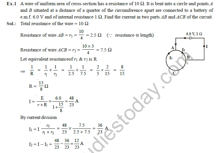
Ex.1: A wire of uniform area of cross-section has a resistance of 10 Ω. It is bent into a circle and points A and B situated at a distance of a quarter of the circumference apart are connected to a battery of e.m.f. 6.0 V and of internal resistance 1 Ω. Find the current in two parts AB and ACB of the circuit.
[Figure: A circular wire with points A and B on it, a quarter of the circumference apart. The arc AB is one part and the arc ACB (three quarters) is the other. A battery of 6.0 V with internal resistance 1 Ω is connected across A and B, with currents I1 in arc AB and I2 in arc ACB.]
Answer:
1. Total resistance of the wire = 10 Ω, so resistance of arc AB: r1 = 10 / 4 = 2.5 Ω.
2. Resistance of arc ACB: r2 = 10 × 3 / 4 = 7.5 Ω.
3. Equivalent resistance of the two arcs in parallel: 1 / R = 1 / 2.5 + 1 / 7.5 = 2 / 5 + 2 / 15 = 8 / 15, so R = 15 / 8 Ω.
4. Total current I = E / (r + R) = 6.0 / (1 + 15 / 8) = 48 / 23 A.
5. By current division, I1 = I × r2 / (r1 + r2) = (48 / 23) × (7.5 / 10) = 36 / 23 A.
6. I2 = I - I1 = 48 / 23 - 36 / 23 = 12 / 23 A.
7. Hence, current in AB = 36 / 23 A (about 1.57 A) and in ACB = 12 / 23 A (about 0.52 A).
Teacher's Note:
a) Resistance of a wire is proportional to its length, so the quarter arc has one quarter of the resistance.
b) The two arcs are in parallel between A and B.
c) Include the 1 Ω internal resistance of the battery in the total resistance.
Ex.2: A uniform copper wire of mass 2.23 gm carries a current of 1 A when an e.m.f. of 1.7 volt is applied across it. Find the length and area of cross-section. If the wire is uniformly stretched to double its lengt, find the new resistance. Density of copper = 8.92 × 10³ kg/m3 and its resistivity is 1.7 × 10⁻⁸ Ω m.
Answer:
1. Resistance of the wire: R = V / I = 1.7 / 1 = 1.7 Ω.
2. Volume of the wire: L × A = mass / density = (2.23 × 10⁻³) / (8.92 × 10³) = 2.5 × 10⁻⁷ m³. ........(i)
3. From R = ρL / A: L / A = R / ρ = 1.7 / (1.7 × 10⁻⁸) = 108. ........(ii)
4. Multiplying (i) and (ii): L² = 2.5 × 10-7 × 108 = 25, so L = 5 m.
5. A = (L × A) / L = 2.5 × 10⁻⁷ / 5 = 5 × 10⁻⁸ m².
6. When the wire is stretched to twice its length, its volume is constant: A' × 2L = A × L, so A' = A / 2 = 2.5 × 10⁻⁸ m².
7. New resistance R' = ρ(2L) / A' = 4ρL / A = 4 × 1.7 = 6.8 Ω.
Teacher's Note:
a) Multiplying the volume equation by the L / A equation removes A and gives L directly.
b) Stretching keeps the volume constant, so the area becomes half when the length doubles.
c) Resistance changes by a factor of 4 when the length doubles at constant volume.
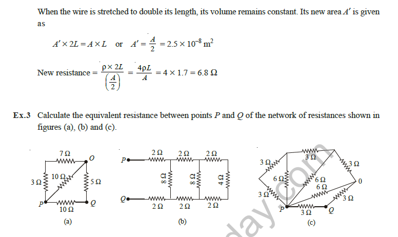
Ex.3: Calculate the equivalent resistance between points P and Q of the network of resistances shown in figures (a), (b) and (c).
[Figure: (a) Square-like network with corners P (bottom left), O (top right), Q (bottom right) and a top left corner. P to top left is 3 Ω, top left to O is 7 Ω, P to O is a diagonal 10 Ω, O to Q is 5 Ω, and P to Q along the bottom is 10 Ω. (b) A ladder between P and Q: a top rail P, 2 Ω, node, 2 Ω, node, 2 Ω, then to the right end; a bottom rail Q, 2 Ω, node, 2 Ω, node, 2 Ω; three vertical rungs of 8 Ω, 8 Ω and 4 Ω between the rails. (c) A network with terminals P and Q: 3 Ω, 3 Ω and 6 Ω branches on the left and top, a 6 Ω branch from the top middle node to P, a 6 Ω diagonal from the top right node to P, a 6 Ω branch from P to node O, 3 Ω from O to Q, a 3 Ω from the top right node to O, and a 3 Ω wire from P to Q.]
Answer:
(a)
1. The 3 Ω and 7 Ω in series give 10 Ω, which is in parallel with the 10 Ω between P and O: 10 × 10 / (10 + 10) = 5 Ω.
2. This 5 Ω is in series with the 5 Ω from O to Q, giving 10 Ω between P and Q.
3. This 10 Ω is in parallel with the direct 10 Ω between P and Q, giving 10 × 10 / 20 = 5 Ω.
4. Hence, RPQ = 5 Ω.
(b)
1. The right-most 2 Ω, 4 Ω and 2 Ω in series give 8 Ω, which is in parallel with the 8 Ω rung: 8 × 8 / 16 = 4 Ω.
2. Adding the next 2 Ω on each rail gives 2 + 4 + 2 = 8 Ω, which is in parallel with the middle 8 Ω rung: 4 Ω.
3. Adding the outer 2 Ω on each rail gives 2 + 4 + 2 = 8 Ω between P and Q.
4. Hence, RPQ = 8 Ω.
(c)
1. The 3 Ω and 3 Ω on the left in series give 6 Ω, which is in parallel with the 6 Ω branch: 6 × 6 / 12 = 3 Ω.
2. The reduction continues in the same way, and so on. At last, there is a 3 Ω resistance along PO in series with 3 Ω along OQ, which is equal to 6 Ω.
3. The 3 Ω resistance along PQ in parallel with the 6 Ω gives the equivalent 6 × 3 / (6 + 3) = 2 Ω between P and Q.
4. Hence, RPQ = 2 Ω.
Teacher's Note:
a) Group resistances from the sides farthest from P and Q first.
b) Series resistances add, and parallel pairs use the product over the sum.
c) For network (c), a nodal analysis gives the same value of 2 Ω, which confirms the reduction.
Ex.4: Calculate the equivalent resistances between points P and Q of the network of resistances shown in figures (a), (b) and (c).
[Figure: (a) Bridge network with P joined to node A. A to B is 4 Ω, A to D is 8 Ω, B to C is 6 Ω, D to C is 12 Ω, the diagonal B to D is 10 Ω, and C joins Q. (b) Network with P joined to A; A to B is R, A to E is R, E to D is R, B to D is 3R, B to F is R, F to C is R, D to C is 4R, and C joins Q. (c) Triangle network with corners B (top), D (bottom left) and C (bottom right), and a centre node A. The sides are 2R (B to D), R (B to C) and R (D to C). Inner branches are R (B to A), R (A to D), R (A to C). Terminals P and Q are near the centre.]
Answer:
(a)
1. The bridge is balanced, since 4 / 6 = 8 / 12, so no current flows through the 10 Ω arm BD and it can be removed.
2. Between P and Q, the path through A, B and C is 4 Ω + 6 Ω = 10 Ω, and the path through A, D and C is 8 Ω + 12 Ω = 20 Ω.
3. These two paths are in parallel: 1 / Req = 1 / 10 + 1 / 20 = 3 / 20.
4. Hence, Req = 20 / 3 ≈ 6.67 Ω.
(b)
1. The bridge is balanced, so the 3R arm BD carries no current and is ineffective.
2. The arms AB, BF, FC on one side give R + R + R, and the arms AE, ED, DC on the other side give R + 4R along the lower path; the reduced network gives Req = 2R.
3. Hence, Req = 2R.
(c)
1. The circuit is a balanced Wheatstone bridge in which each arm has resistance R, and the 2R arm across BD is ineffective.
2. Two equal paths of R + R = 2R each are in parallel: 1 / Req = 1 / 2R + 1 / 2R.
3. Hence, Req = (2R × 2R) / (2R + 2R) = R.
Teacher's Note:
a) Check the bridge balance condition first: the product of opposite arms must be equal.
b) A balanced bridge arm carries no current and can be removed or ignored.
c) Part (c) follows the printed working; the figure labels are small, so check them against the original diagram.
Ex.5: A battery of 6.0 V is connected to an infinite network of resistances of 1Ω connected in series and 2Ω in parallel as shown in the circuit. Find (a) effective resistance between A and B (b) the current through 2Ω resistance nearest to the battery.
[Figure: An infinite ladder. Along the top rail from A there are 1 Ω resistors in series, and at each junction a 2 Ω resistor joins the top rail to the bottom rail. The bottom rail connects to B. A 6.0 V battery is connected across A and B, and the ladder continues to infinity.]
Answer:
(a)
1. Let R be the resistance between A and B. Adding one more section (1 Ω in series and 2 Ω in parallel) does not change an infinite network, so the resistance remains R.
2. The 2 Ω in parallel with R gives 2R / (2 + R), so R = 1 + 2R / (2 + R).
3. Simplifying: R² - R - 2 = 0, so (R + 1)(R - 2) = 0.
4. R = -1 Ω is not possible, so R = 2 Ω.
(b)
1. Current from the battery: I = 6.0 / 2 = 3 A.
2. Beyond the first 1 Ω, the rest of the ladder has resistance 2 Ω, so the first 2 Ω section between the two junctions is in parallel with 2 Ω: 2 × 2 / (2 + 2) = 1 Ω.
3. Voltage across this section: V = 3 × 1 = 3 V.
4. Current through the 2 Ω resistor nearest to the battery = 3 / 2 = 1.5 A.
Teacher's Note:
a) Adding a section to an infinite ladder does not change its resistance, which gives the equation.
b) Reject the negative root, since a resistance cannot be negative.
c) The current in the 2 Ω resistor is 1.5 A, while the 1 Ω resistor in series carries 3 A.
Ex.6: Twelve wires, each of resistance 6Ω are connected to form a network of skelton cube. A current enters at one corner and leaves from the diagonally opposite corner. Find the effective resistance between the opposite corners.
[Figure: A skeleton cube with corners A (entry), G (exit, diagonally opposite), and the other six corners B, C, D, E, F and H, each edge a 6 Ω wire. The current i enters at A and divides equally along the three edges from A, and leaves at G through the three edges meeting G.]
Answer:
1. By symmetry, the current i entering at A divides equally into the three edges from A, so each carries i / 3.
2. At each intermediate corner, the current divides equally among the remaining edges, so the path A to G through one route B, C, G carries i / 3, i / 6 and i / 3 along its three edges.
3. The voltage drop along one route A to G is VAG = (i/3)r + (i/6)r + (i/3)r = (5i / 6) r.
4. So Req = VAG / i = (5 / 6) r = (5 / 6) × 6 = 5 Ω.
Teacher's Note:
a) Symmetry means the currents on equivalent edges are equal.
b) Use the current through each edge, not the total current, along one path.
c) The general result for a cube is 5r / 6, which equals 5 Ω here.
Ex.7. Find the potential difference between points B and C in the circuit shown in the figure where the battery of 1.5 V has an internal resistance of 2Ω and the battery of 2V has an internal resistance of 1Ω.
[Figure: Rectangular circuit with nodes A (top left), D (top right), B (middle left), C (middle right), E (bottom left) and F (bottom right). A to D on the top has a 1.5 V battery in series with a 2 Ω internal resistance. A to B is 2 Ω and B to E is 2 Ω. D to C is 3 Ω and C to F is 3 Ω. B to C is 8 Ω. E to F on the bottom has a 2 V battery in series with a 1 Ω internal resistance.]
Answer:
1. Let the potential of F be 0 V, and let VA, VB, VC, VD and VE be the potentials of the other nodes.
2. Current from D to A through the top branch: IDA = (VD - VA + 1.5) / 2.
3. Current from F to E through the bottom branch: J = VF + 2 - VE.
4. Node A: (VA - VB) / 2 = IDA.
5. Node D: IDA + (VD - VC) / 3 = 0.
6. Node B: (VB - VA) / 2 + (VB - VE) / 2 + (VB - VC) / 8 = 0.
7. Node C: (VC - VD) / 3 + (VC - VB) / 8 + (VC - VF) / 3 = 0.
8. Node E: (VE - VB) / 2 = J, and node F: (VF - VC) / 3 + J = 0.
9. Solving these equations gives VA = 124/73 V, VB = 119/73 V, VC = 27/73 V, VD = 39/146 V and VE = 137/73 V.
10. Current through the 8 Ω resistor from B to C: i1 = 23 / 146 A.
11. Hence, VB - VC = 8 × 23 / 146 = 92 / 73 V, which is about 1.26 V.
Kirchhoff's-law method (as in the original solution):
Let the current be i in the branch containing the 1.5 V cell, i1 in the 8 Ω resistor from B to C, and i - i1 in the branch containing the 2 V cell.
Applying Kirchhoff's second law to loops ADCBA and BCFEB:
Loop ADCBA: -1.5 + 2i + 3i + 8i1 + 2i = 0, or 7i + 8i1 = 1.5 ...(i)
Loop BCFEB: -8i1 + 3(i - i1) + 1(i - i1) + 2 + 2(i - i1) = 0, or 3i - 7i1 = -1 ...(ii)
Solving (i) and (ii): i1 = 23 / 146 A and i = 3 / 146 A.
Potential difference between B and C: VB - VC = 8 × 23 / 146 = 92 / 73 V.
Teacher's Note:
a) An internal resistance adds to the resistance of its branch.
b) Note the polarity of each cell: the EMF rises from the negative to the positive terminal.
c) The 8 Ω branch alone gives the potential difference once the branch current is known.
Ex.8 In the circuit shown, find: (a) potential difference between B and D (b) potential difference across cell of 1V between B and C and cell of 3V between C and D
[Figure: Four-point circuit with nodes A (top left), B (top right), C (bottom right) and D (bottom left). A to B has a 2 V cell in series with a 2 Ω resistor, the cell's polarity as drawn. A to D is 1 Ω. B to C has a 1 V cell in series with a 1 Ω resistor. C to D has a 3 V cell in series with a 3 Ω resistor. The diagonal from B to D has a 2 Ω resistor. The current i flows from A to B on the top, the current i - i1 flows down from B to C, and i1 flows along the diagonal from B towards D.]
Answer:
1. Loop ABDA: -2 - 2i - 2i1 - 1 × i + 1 = 0, so 3i + 2i1 = -1. ........(i)
2. Loop BCDB: -1(i - i1) + 1 - 3 - 3(i - i1) + 2i1 = 0, so 4i - 6i1 = -2. ........(ii)
3. Solving (i) and (ii): i1 = 1 / 13 A and i = -5 / 13 A.
4. (a) VB - VD = -2 / 13 V.
5. (b) i - i1 = -5 / 13 - 1 / 13 = -6 / 13 A.
6. Potential difference across the 1 V cell between B and C: VBC = 1 + 1 × 6 / 13 = 19 / 13 V.
7. Potential difference across the 3 V cell between C and D: VDC = 3 - (6 / 13) × 3 = 21 / 13 V.
Teacher's Note:
a) Current direction is found from the sign of the solution; a negative value means the assumed direction is reversed.
b) Use Kirchhoff's voltage law around each loop, with the EMF sign taken from the cell direction.
c) Check the answer by recomputing the potential difference through a different path.
Ex.9: Two capacitors C1 = 10 μF and C2 = 20 μF are connected in the circuit diagram showing three cells of E.M.F. 12V, 6V and 3V connected alongwith various resistors. In the steady state, find: (a) the currents I1, I2 and I3 (b) the energy stored in capacitors C1 and C2.
[Figure: Circuit with three cells of EMF 12 V, 6 V and 3 V, resistors of 10 Ω, 5 Ω and 10 Ω, capacitor C1 = 10 μF on the left side of the circuit near the 3 V cell, and capacitor C2 = 20 μF on the right side of the circuit, next to junction D. Currents I1, I2 and I3 are marked at junction D.]
Answer:
1. In steady state, no current flows through a capacitor, so I1 = 0 in the branch with C2.
2. Kirchhoff's first law at junction D: I1 - I2 - I3 = 0, so I3 = -I2.
3. Applying Kirchhoff's second law to the mesh containing the 3 V and 6 V cells: 15I3 - 5(-I3) = -9, so I3 = -9 / 20 A.
4. Hence, I2 = 9 / 20 A, I3 = -9 / 20 A and I1 = 0. The current I3 flows opposite to the direction shown in the figure.
5. Potential difference across C1: V1 = -5I3 - 3 = -(5 × (-9 / 20)) - 3 = -3 / 4 V. The negative sign shows that the polarity is opposite to that shown.
6. Energy stored in C1: U1 = ½ C1 V1² = ½ × 10 × 10-6 × (3 / 4)² = 2.8 × 10⁻⁶ J.
7. Potential difference across C2: V2 = 5I2 - 12 = 5 × 9 / 20 - 12 = -39 / 4 V.
8. Energy stored in C2: U2 = ½ C2 V2² = ½ × 20 × 10-6 × (39 / 4)² = 9.506 × 10⁻⁴ J.
Teacher's Note:
a) A capacitor in steady state behaves as an open circuit.
b) Energy of a capacitor is ½CV², so use the magnitude of the voltage.
c) A negative current or voltage only shows the true direction is opposite to the assumed one.
Ex.10. An electric tea kettle has two heating coils. When one of the coils is switched on, the water in the kettle begins to boil in 6 minutes. When only the other coil is switched on, the boiling starts in 8 minutes. Find the time it will take so that boiling begins when both the coils are switched on simultaneously if these are connected (a) in series (b) in parallel.
Answer:
1. For a constant heat H = V²t / R, so t is proportional to R.
2. From t1 / t2 = R1 / R2 = 6 / 8 = 3 / 4, we get R2 = 4R1 / 3.
3. (a) In series: R' = R1 + R2 = R1 + 4R1 / 3 = 7R1 / 3.
4. So ts = 6 × (7R1 / 3) / R1 = 14 min.
5. (b) In parallel: R'' = R1R2 / (R1 + R2) = (4R1 / 7).
6. So tp = 6 × (4 / 7) = 24 / 7 ≈ 3.43 min.
Teacher's Note:
a) Boiling time is proportional to the resistance when the voltage is fixed.
b) The series combination has the larger resistance, so it takes longer.
c) The parallel combination has less resistance than either coil alone, so it boils fastest.
Ex.11: A cell of steady emf. 2.0 V is put across a potentiometer wire. For finding internal resistance of a cell of emf 1.5 V, it is connected as shown under. The balance point for this cell in open circuit is 76.3 cm. When a resistance of 9.5 Ω is put across this cell, the balance point shifts to 64.8 cm. Find the internal resistance of the cell.
[Figure: Potentiometer wire driven by a 2.0 V cell. The 1.5 V cell is connected through a galvanometer G to the wire, and a resistance of 9.5 Ω can be connected across the 1.5 V cell.]
Answer:
1. Given: R = 9.5 Ω, l1 = 76.3 cm (open circuit), l2 = 64.8 cm (with R), and internal resistance r is to be found.
2. The EMF of the cell is E = kl1 in open circuit, and the terminal voltage is V = kl2 with the resistance connected.
3. Since V = E R / (R + r), we get E / V = (R + r) / R, so l1 / l2 = 1 + r / R.
4. Hence, r = R (l1 / l2 - 1) = 9.5 × (76.3 / 64.8 - 1) = 9.5 × 0.1775 = 1.686 Ω.
5. Hence, the internal resistance is about 1.69 Ω.
Teacher's Note:
a) The balance lengths are lengths in centimetres, not ohms; the printed "Ω" after 76.3 and 64.8 is a unit error.
b) The ratio of balance lengths removes the unknown potential gradient of the wire.
c) A larger drop in balance length means a larger internal resistance.
Free study material for Physics
Free CBSE Study Guides: Class 12 Physics Chapter 01 Electric Charges and Fields
Essential Notes for Class 12 Physics
Review targeted study resources for Chapter 01 Electric Charges and Fields tailored for Class 12 learners. Utilizing these structured notes and quick-revision tools ensures complete alignment with current CBSE evaluation standards.
Verified Solutions for Class 12 Physics
Each resource draws directly from authorized textbooks to maintain academic accuracy. Evaluating solved examples allows Class 12 students to master the formal presentation and answer-writing standards expected in upcoming school exams.
Enhance Accuracy with Online Tests
For peak performance in upcoming evaluations, integrate official Physics sample papers directly into your study schedule. Follow up your revision by attempting online MCQ tests for Chapter 01 Electric Charges and Fields to refine calculation speed and precision.
FAQs
Our advanced study package for Chapter 01 Electric Charges and Fields includes detailed concepts, diagrams, Mind Maps, and explanation of complex topics to ensure Class 12 students learn as per syllabus for 2026 exams.
The Mind Maps provided for Chapter 01 Electric Charges and Fields act as visual anchors which will help faster recall during high-pressure exams.
Yes, teachers use our Class 12 Physics resources for lesson planning as they are in simple language and have lot of solved examples.
Yes, You can download the complete, mobile-friendly PDF of the Physics Chapter 01 Electric Charges and Fields advanced resources for free.
Yes, our subject matter experts have updated the Chapter 01 Electric Charges and Fields material to align with the rationalized NCERT textbooks and have removed deleted topics and added new competency-based questions.