

Download CBSE Class 12 Physics Useful Resources
Explore structured advanced study materials through the CBSE Class 12 Physics Electric Circuits Objective Questions. Tailored for Class 12 learners, utilizing these Physics resources ensures thorough preparation and strengthens foundational knowledge before final CBSE evaluations.
Access CBSE Study Guides and Summaries
View or download the dedicated CBSE Class 12 Physics Electric Circuits Objective Questions resource below. Engaging with these advanced study guides under focused conditions ensures continuous academic progress and mastery of the 2026-27 curriculum for Chapter 01 Electric Charges and Fields.
CBSE Class 12 Physics Electric Circuits Objective Questions. Please refer to the examination notes which you can use for preparing and revising for exams. These notes will help you to revise the concepts quickly and get good marks.
CLASS 12 PHYSICS : ELECTRIC CIRCUITS
OBJECTIVE QUESTIONS
1. Calculate the resistance between P and Q in the following network. Each element has resistance 3Ω.
(a) 6 Ω
(b) 4 Ω
(c) 3 Ω
(d) 2 Ω

[Figure: A square network with corners a (top left), b (top right), c (bottom right) and d (bottom left). P is joined to a and Q is joined to c; a short wire also extends from b to the right and ends in the air. Each side ab, bc, cd, da is a resistor, and each of the four resistors from the corners to the centre O (aO, bO, cO, dO) is also a resistor, all of 3 Ω]
Answer: (d) 2 Ω
1. P is connected to corner a and Q to corner c. The wire at b is free and carries no current.
2. By symmetry, corners b, d and the centre O are all at the same potential, which is midway between those of a and c, so the resistors joining b, d and O to one another carry no current.
3. The three paths a-b-c, a-d-c and a-O-c each have a resistance of 3 + 3 = 6 Ω and are in parallel.
4. Three 6 Ω paths in parallel: R = \( \frac{6}{3} \) = 2 Ω.
5. Hence, the correct option is (d).
Teacher's Note:
a) Use symmetry: points at equal potential can be joined or separated without changing the resistance.
b) Do not count the dangling wire at b; no current flows in it.
2. The resistance between P and Q in the following combination of resistances is
(a) 8 Ω
(b) 6 Ω
(c) 5 Ω
(d) 4 Ω

[Figure: Main line from P to Q has three resistors in series: 4 Ω, 4 Ω and 8 Ω. A wire from the junction after the first 4 Ω rises and runs over the top through a separate 8 Ω resistor to a vertical wire that comes down to the main line just before Q. A second loop from the junction after the second 4 Ω rises and goes through another 8 Ω resistor to the same vertical wire]
Answer: (a) 8 Ω
1. The 8 Ω resistor in the inner loop and the 8 Ω resistor on the main line (the last one before Q) are joined between the same two points, so they are in parallel: \( \frac{8 \times 8}{8 + 8} \) = 4 Ω.
2. This 4 Ω is in series with the middle 4 Ω resistor: 4 + 4 = 8 Ω.
3. The big 8 Ω resistor at the top joins the same two end points, so it is in parallel with this 8 Ω: \( \frac{8}{2} \) = 4 Ω.
4. Adding the first 4 Ω resistor in series, the total = 4 + 4 = 8 Ω.
5. Hence, the correct option is (a).
Teacher's Note:
a) Trace each wire to see which resistors share the same two end points before combining them.
b) Combine from the inside outwards: parallel first, then series, then parallel again.
3. The effective resistance between points P and Q is
(a) 150 Ω
(b) 120 Ω
(c) 90 Ω
(d) 80 Ω
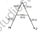
[Figure: A triangular A-shaped network. The top apex is joined by a 30 Ω resistor to the left middle node and by a 30 Ω resistor to the right middle node. A 30 Ω crossbar joins the left and right middle nodes. A 30 Ω resistor runs from the left middle node down to terminal P, and a 30 Ω resistor runs from the right middle node down to terminal Q]
Answer: (d) 80 Ω
1. Let the left leg be P - 30 Ω - L - 30 Ω - top, and the right leg be top - 30 Ω - R - 30 Ω - Q, with a 30 Ω crossbar between L and R.
2. Between L and R: the crossbar 30 Ω is in parallel with the path L - top - R of 30 + 30 = 60 Ω, giving \( \frac{30 \times 60}{30 + 60} \) = 20 Ω.
3. Total resistance = 30 + 20 + 30 = 80 Ω.
4. Hence, the correct option is (d).
Teacher's Note:
a) Identify the loop that forms a parallel combination before adding the series arms.
b) The terminals P and Q are at the feet of the two legs, so the two outer 30 Ω resistors are in series with the middle part.
4. Six resistances, each equal to 4 Ω are connected as shown in the figure. The effective resistance between any two vertices is
(a) 2 Ω
(b) 8 Ω
(c) 12 Ω
(d) 16 Ω
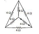
[Figure: A triangle with a 4 Ω resistor on each of its three sides, and a point at the centre joined by a 4 Ω resistor to each of the three vertices]
Answer: (a) 2 Ω
1. The network has four nodes (three vertices and the centre), and every pair of nodes is joined by a 4 Ω resistor, so it is symmetric.
2. Take two vertices A and B. The direct resistor 4 Ω is in parallel with the path through the third vertex (4 + 4 = 8 Ω) and the path through the centre (4 + 4 = 8 Ω), because the third vertex and the centre are at the same potential.
3. \( \frac{1}{R} \) = \( \frac{1}{4} \) + \( \frac{1}{8} \) + \( \frac{1}{8} \) = \( \frac{1}{2} \), so R = 2 Ω.
4. Hence, the correct option is (a).
Teacher's Note:
a) A balanced (symmetric) network with equal resistors on every pair of four nodes has equivalent resistance R/2 between any two nodes.
b) The two remaining nodes are at equal potential, so the resistor joining them carries no current.
5. The equivalent resistance between the points A and B of the following circuit is
(a) 5 Ω
(b) 10 Ω
(c) 15 Ω
(d) 20 Ω
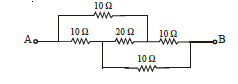
[Figure: Main line from A to B with resistors 10 Ω, 20 Ω and 10 Ω in series. A 10 Ω resistor is connected over the top from A to the point between the 20 Ω and the last 10 Ω. A 10 Ω resistor is connected underneath from the point between the first 10 Ω and the 20 Ω to B]
Answer: (b) 10 Ω
1. Let the nodes on the main line be A, X (after the first 10 Ω), Y (after the 20 Ω) and B (after the last 10 Ω).
2. The resistors are: A-X 10 Ω, X-Y 20 Ω, Y-B 10 Ω, A-Y 10 Ω (top arc) and X-B 10 Ω (bottom arc).
3. Taking VA = V and VB = 0, solving the node equations at X and Y gives VX = \( \frac{V}{2} \) and VY = \( \frac{V}{2} \). Then X and Y are at the same potential, so the 20 Ω carries no current.
4. Resistance between A and B = (10 ∥ 10) + (10 ∥ 10) = 5 + 5 = 10 Ω.
5. Hence, the correct option is (b).
Teacher's Note:
a) This is a balanced bridge: the ratio of the resistors on the two arms is equal, so the middle 20 Ω carries no current.
b) When a bridge is balanced, remove the middle resistor and then combine the remaining ones in series and parallel.
6. Seven resistors, each of 1 Ω, are connected as shown in the figure. The effective resistance between P and Q is
(a) \( \frac{4}{3} \) Ω
(b) \( \frac{8}{7} \) Ω
(c) \( \frac{3}{2} \) Ω
(d) 7 Ω
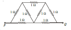
[Figure: Seven 1 Ω resistors forming two triangles on a base line from P to Q. The base line has a 1 Ω resistor from the left corner node to the middle bottom node and a 1 Ω resistor from the middle bottom node to the right corner node. The left triangle has a 1 Ω resistor from the left corner node up to the top-left apex, and a 1 Ω resistor from this apex down to the middle bottom node. The right triangle has a 1 Ω resistor from the middle bottom node up to the top-right apex and a 1 Ω resistor from this apex down to the right corner node. A 1 Ω resistor joins the two apexes across the top. P is joined to the left corner node and Q to the right corner node]
Answer: (b) \( \frac{8}{7} \) Ω
1. Name the nodes: L (joined to P), M (bottom middle), R (joined to Q), T1 (top left) and T2 (top right).
2. The resistors are L-T1, T1-T2, T1-M, M-T2, T2-R, L-M and M-R, each 1 Ω.
3. Write the node equations with VL = V and VR = 0 and solve them for the unknown potentials.
4. The total current drawn comes out as \( \frac{7V}{8} \), so Req = \( \frac{V}{I} \) = \( \frac{8}{7} \) Ω.
5. Hence, the correct option is (b).
Teacher's Note:
a) The circuit is not a simple series-parallel network, so use junction equations (Kirchhoff) or the star-delta transformation.
b) Check the answer against the bounds: it must be less than the smallest path resistance of 2 Ω from P to Q.
7. The resistance across points D and E of the circuit is
(a) \( \frac{R}{2} \)
(b) \( \frac{R}{3} \)
(c) \( \frac{R}{4} \)
(d) 2R

[Figure: A triangle ABC with apex A at the top. From A two outer resistors R run down to B and C. From A a wire goes down the middle and then splits into two inner resistors R which meet wires leading to B and C. Two more resistors R lie horizontally between the left and right sides, one at the middle level and one at the base between B and C. D is a terminal wire joined to B and E is a terminal wire joined to C]
Answer: (b) \( \frac{R}{3} \)
1. D and E are joined by plain wires to B and C, so find the resistance between B and C.
2. A is joined to B through two resistors R in parallel (the outer one and the inner one), giving \( \frac{R}{2} \), and to C in the same way, giving \( \frac{R}{2} \). This path from B to C through A has resistance \( \frac{R}{2} \) + \( \frac{R}{2} \) = R.
3. The horizontal resistor R in the middle and the bottom resistor R also join B and C directly.
4. Three resistances R in parallel: Req = \( \frac{R}{3} \).
5. Hence, the correct option is (b).
Teacher's Note:
a) Plain wires have zero resistance, so points joined by a wire are the same node.
b) Count every independent path between the two end points before combining.
8. Five cells each of internal resistance 0.2 and e.m.f. 2V are connected in series with a resistance of 4Ω. The current through the external resistance is
(a) 0.2 A
(b) 0.5 A
(c) 1 A
(d) 2 A
Answer: (d) 2 A
1. Total e.m.f. of five cells in series = 5 × 2 = 10 V.
2. Total internal resistance = 5 × 0.2 = 1 Ω.
3. Current I = \( \frac{10}{4 + 1} \) = 2 A.
4. Hence, the correct option is (d).
Teacher's Note:
a) For cells in series, add both the e.m.f.s and the internal resistances.
9. Assume that the internal resistance of battery is zero and the key is closed in the following circuit, the reading of the ammeter is
(a) 0.25 A
(b) 0.5 A
(c) 1.0 A
(d) 2.0 A
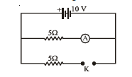
[Figure: A 10 V battery (positive terminal on the left) connected across two parallel branches. The first branch has a 5 Ω resistor in series with an ammeter A. The second branch has a 5 Ω resistor in series with a key K]
Answer: (d) 2.0 A
1. The battery has no internal resistance, so the full 10 V is across each parallel branch.
2. The ammeter is in the branch with the 5 Ω resistor, so the reading = \( \frac{10}{5} \) = 2 A.
3. The other branch (also 5 Ω, closed by K) does not change the current in the ammeter branch.
4. Hence, the correct option is (d).
Teacher's Note:
a) In parallel branches across an ideal battery, each branch current depends only on its own resistance.
b) An ideal ammeter has no resistance, so it does not change the current.
10. In the following circuit, the reading of the voltmeter is
(a) 5 V
(b) 10 V
(c) 15 V
(d) 16.5 V
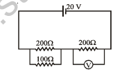
[Figure: A 20 V battery in a loop with two series sections. The left section is a 200 Ω resistor with a 100 Ω resistor connected across it in parallel. The right section is a 200 Ω resistor with a voltmeter V connected across it]
Answer: (c) 15 V
1. The 100 Ω resistor is in parallel with the left 200 Ω resistor: \( \frac{200 \times 100}{200 + 100} \) = \( \frac{200}{3} \) Ω.
2. The voltmeter is connected across the right 200 Ω resistor and, being ideal, draws no current.
3. Total resistance = \( \frac{200}{3} \) + 200 = \( \frac{800}{3} \) Ω.
4. Current = \( \frac{20}{800/3} \) = 0.075 A.
5. Reading of the voltmeter = 0.075 × 200 = 15 V.
6. Hence, the correct option is (c).
Teacher's Note:
a) An ideal voltmeter has infinite resistance and does not change the current.
b) The voltmeter reads the p.d. across the 200 Ω resistor it is connected to, not across the whole circuit.
11. A cell of e.m.f. E is connected across a resistance R. The potential difference between the terminals of a cell is measured equal to V. The internal resistance of the cell is
(a) (E - V)R
(b) \( \frac{2(E - V)R}{V} \)
(c) \( \frac{2(E - V)R}{E} \)
(d) \( \frac{(E - V)R}{V} \)
Answer: (d) \( \frac{(E - V)R}{V} \)
1. The terminal voltage V = IR, so the current I = \( \frac{V}{R} \).
2. The lost voltage inside the cell = E - V = Ir.
3. r = \( \frac{E - V}{I} \) = \( \frac{(E - V)R}{V} \).
4. Hence, the correct option is (d).
Teacher's Note:
a) Use V = E - Ir and V = IR together.
12. In the circuit shown in the figure, the heat produced in the 5 Ω resistor, due to the current flowing through it, is 10 calories per second. The heat generated in the 4 ohm resistor is
(a) 1 cal/s
(b) 2 cal/s
(c) 3 cal/s
(d) 4 cal/s
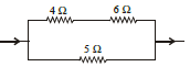
[Figure: A 4 Ω resistor and a 6 Ω resistor in series on the upper branch and a 5 Ω resistor on the lower branch, joined in parallel, with the current entering on the left and leaving on the right]
Answer: (b) 2 cal/s
1. The 4 Ω and 6 Ω resistors are in series, and this branch is in parallel with the 5 Ω resistor, so both branches have the same voltage V.
2. For the 5 Ω resistor, \( \frac{V^{2}}{5} \) = 10, so V² = 50.
3. Heat in the 4 Ω + 6 Ω branch = \( \frac{V^{2}}{10} \) = 5 cal/s.
4. In a series branch the heat is shared in proportion to resistance, so the heat in the 4 Ω resistor = 5 × \( \frac{4}{10} \) = 2 cal/s.
5. Hence, the correct option is (b).
Teacher's Note:
a) In parallel the voltage is the same; in series the current is the same, so heat in a series branch divides in the ratio of the resistances.
13. In the circuit shown in the figure, the current through _______
(a) 3 Ω resistor is 0.5 A
(b) 3 Ω resistor is 0.25 A
(c) 4 Ω resistor is 0.5 A
(d) 4 Ω resistor is 0.25 A
[Figure: A ladder network with a 9 V cell at the left end. Top wire from the cell: 3 Ω, then 2 Ω, then 2 Ω. Bottom wire from the cell: 2 Ω, then 2 Ω, then 2 Ω. Three vertical resistors join the top and bottom wires: 8 Ω after the 3 Ω resistor, 8 Ω after the first 2 Ω resistor on the top wire, and 4 Ω at the right end]
Answer: (d) 4 Ω resistor is 0.25 A
1. Start from the right end: the right 2 Ω, the 4 Ω and the bottom 2 Ω are in series: 2 + 4 + 2 = 8 Ω.
2. This 8 Ω is in parallel with the second 8 Ω resistor: 4 Ω. Adding the next 2 Ω and 2 Ω in series gives 8 Ω.
3. This 8 Ω is in parallel with the first 8 Ω resistor: 4 Ω. Adding the 3 Ω and the bottom-left 2 Ω gives a total of 9 Ω.
4. Current from the 9 V cell = 1 A, which is the current in the 3 Ω resistor.
5. At each 8 Ω - 8 Ω junction the current divides equally: 0.5 A, then 0.25 A.
6. The current in the 4 Ω resistor = 0.25 A.
7. Hence, the correct option is (d).
Teacher's Note:
a) Reduce a ladder network from the far end towards the battery, then divide the current back along the ladder.
b) The current in the 3 Ω resistor is 1 A, which is not given in options (a) and (b); the 0.25 A in the 4 Ω resistor matches option (d).
14. The current through the resistor in the given circuit is
(a) 1.5 A
(b) 2.5 A
(c) 3.5 A
(d) 5.0 A
[Figure: Three parallel branches between the same two end wires: the top branch has a 10 V cell with internal resistance 3 Ω, the middle branch has a 12 V cell with internal resistance 2 Ω (both cells in the same direction), and the bottom branch has a 2 Ω resistor]
Answer: (c) 3.5 A
1. Three branches are in parallel: a 10 V cell with 3 Ω, a 12 V cell with 2 Ω, and a 2 Ω resistor. The cells are in the same direction.
2. Let V be the p.d. across the resistor. Then \( \frac{10 - V}{3} \) + \( \frac{12 - V}{2} \) = \( \frac{V}{2} \).
3. Multiplying by 6: 2(10 - V) + 3(12 - V) = 3V, so 56 = 8V and V = 7 V.
4. Current through the resistor = \( \frac{7}{2} \) = 3.5 A.
5. Hence, the correct option is (c).
Teacher's Note:
a) Cells in parallel with different e.m.f.s are solved by the junction rule at one node.
b) Check that the sum of the two cell currents equals the resistor current: 1 A + 2.5 A = 3.5 A.
15. The resistance of votlmeter in the given circuit is 800 Ω. The voltmeter will read
(a) 8 V
(b) 16 V
(c) 32 V
(d) 40 V
[Figure: A 40 V battery on the top side of a rectangle. A 40 Ω resistor on the left side, a 120 Ω resistor on the right side and an 80 Ω resistor on the bottom side. A diagonal wire from the bottom-left corner to the top-right corner carries a voltmeter V]
Answer: (c) 32 V
1. Label the corners: TL and TR (battery between them, 40 V), BL and BR. The resistors are 40 Ω (TL-BL), 80 Ω (BL-BR), 120 Ω (BR-TR) and the voltmeter of 800 Ω joins BL and TR.
2. Take VTL = 0 and VTR = 40 V. Node equations: \( \frac{V_{BL}}{40} \) + \( \frac{V_{BL} - V_{BR}}{80} \) + \( \frac{V_{BL} - 40}{800} \) = 0 and \( \frac{V_{BR} - V_{BL}}{80} \) + \( \frac{V_{BR} - 40}{120} \) = 0.
3. Solving, VBL = 8 V and VBR = 20.8 V.
4. The voltmeter reads |VBL - VTR| = |8 - 40| = 32 V.
5. Hence, the correct option is (c).
Teacher's Note:
a) A voltmeter of finite resistance is treated as a resistor connected between its two points.
b) Set one potential as zero and use Kirchhoff's junction rule at the other nodes.
16. The temperature coefficient of resistance of a wire is 0.00125 perºC. At 300 K, its resistance is 1 Ω. The resistance of the wire will be 2 Ω at
(a) 1100 K
(b) 1127 K
(c) 1154 K
(d) 1400 K
Answer: (b) 1127 K
1. Use Rt = R0(1 + αt), where R0 is the resistance at 0°C and α = 0.00125 per °C.
2. At 300 K (27°C): 1 = R0(1 + 0.00125 × 27) = 1.03375 R0.
3. For 2 Ω: 2 = R0(1 + 0.00125 t), so 1 + 0.00125 t = 2 × 1.03375 = 2.0675.
4. t = \( \frac{1.0675}{0.00125} \) = 854°C, so T = 854 + 273 = 1127 K.
5. Hence, the correct option is (b).
Teacher's Note:
a) The coefficient α is defined with respect to the resistance at 0°C, so first find R0.
b) Using 300 K as the reference temperature gives about 1100 K, option (a), which is an approximation and not the exact result.
17. Two electric lamps A and B having power 200 watt and 100 watt respectively are rated on the same voltage. The ratio of resistance of lamp A to that of B is
(a) 1 : 2
(b) 2 : 1
(c) 1 : 4
(d) 4 : 1
Answer: (a) 1 : 2
1. For the same rated voltage, R = \( \frac{V^{2}}{P} \), so R is inversely proportional to P.
2. \( \frac{R_A}{R_B} \) = \( \frac{P_B}{P_A} \) = \( \frac{100}{200} \) = \( \frac{1}{2} \).
3. Hence, the ratio is 1 : 2 and the correct option is (a).
Teacher's Note:
a) A higher-power lamp of the same voltage rating has a lower resistance.
18. In the circuit shown in the figure, the final voltage drop across the capacitor C in steady state is
(a) \( \frac{V r_1}{r_1 + r_2} \)
(b) \( \frac{V r_2}{r_1 + r_2} \)
(c) \( \frac{V(r_1 + r_2)}{r_2} \)
(d) \( \frac{V(r_1 + r_2)}{r_1 + r_2 + r_3} \)
[Figure: A battery of e.m.f. V in a loop with a resistor r1 on the bottom. A resistor r2 is joined vertically between the top wire and the bottom wire. To the right, a resistor r3 in the top wire is in series with the capacitor C, which is connected down to the bottom wire]
Answer: (b) \( \frac{V r_2}{r_1 + r_2} \)
1. In the steady state no current flows in the branch with r3 and C, so r3 has no potential drop.
2. The current flows through r1 and r2 only: I = \( \frac{V}{r_1 + r_2} \).
3. The capacitor is connected across r2 (through r3), so its voltage = I r2 = \( \frac{V r_2}{r_1 + r_2} \).
4. Hence, the correct option is (b).
Teacher's Note:
a) A capacitor blocks steady current, so a resistor in series with it has no voltage across it.
b) The capacitor charges to the voltage of the part of the circuit it is connected across.
19. Three capacitors of capacitance 3 μF each are connected in series. The energy stored in the capacitances, when a potential of 1 kilo volt is applied to these for charging, is
(a) 5 J
(b) 0.5 J
(c) 0.005 J
(d) 50 J
Answer: (b) 0.5 J
1. Equivalent capacitance in series: \( \frac{1}{C} \) = \( \frac{1}{3} \) + \( \frac{1}{3} \) + \( \frac{1}{3} \) = 1 per μF, so C = 1 μF.
2. Energy U = \( \frac{1}{2} \) CV² = \( \frac{1}{2} \) × 1 × 10⁻⁶ × (1000)² = 0.5 J.
3. Hence, the correct option is (b).
Teacher's Note:
a) Convert 1 kV to 1000 V and μF to 10⁻⁶ F before substituting.
20. A battery of e.m.f. 10 V is connected to resistances as shown in the figure. The potential difference between A and B is
(a) -2 V
(b) +2 V
(c) -5 V
(d) 5 V
[Figure: Two parallel branches connected across a 10 V battery (positive terminal on the left). Upper branch from left to right: 1 Ω resistor, point A, 3 Ω resistor. Lower branch from left to right: 3 Ω resistor, point B, 1 Ω resistor]
Answer: (d) 5 V
1. Two branches are in parallel across the 10 V battery. The upper branch is 1 Ω and 3 Ω in series with point A between them; the lower branch is 3 Ω and 1 Ω in series with point B between them.
2. Taking the left end as 10 V and the right end as 0: VA = 10 - \( \frac{1}{4} \) × 10 = 7.5 V.
3. VB = 10 - \( \frac{3}{4} \) × 10 = 2.5 V.
4. VA - VB = 7.5 - 2.5 = 5 V.
5. Hence, the correct option is (d).
Teacher's Note:
a) Each branch is a potential divider; find each midpoint potential and subtract.
b) Take care of the order of the resistors: the 1 Ω is on the left in the upper branch but on the right in the lower branch.
21. A torch bulb rated as 4.5 W, 1.5 V is connected as shown in the figure. The e.m.f. of the cell of internal resistance 2.67 Ω, needed to make the bulb glow at full intensity is
(a) 4.5 V
(b) 6.75 V
(c) 13.5 V
(d) 27 V
[Figure: A torch bulb marked 4.5 W, 1.5 V at the top, a 1 Ω resistor in the middle and a cell E with internal resistance r = 2.67 Ω at the bottom, all connected in parallel between the same two vertical wires]
Answer: (c) 13.5 V
1. Current in the bulb at full intensity = \( \frac{P}{V} \) = \( \frac{4.5}{1.5} \) = 3 A.
2. The 1 Ω resistor is in parallel with the bulb, so the current in it = \( \frac{1.5}{1} \) = 1.5 A.
3. Total current from the cell = 3 + 1.5 = 4.5 A.
4. E = V + I r = 1.5 + 4.5 × 2.67 = 13.5 V (approximately).
5. Hence, the correct option is (c).
Teacher's Note:
a) The bulb, the 1 Ω resistor and the cell are all connected across the same two points, so the terminal voltage is 1.5 V.
b) Add the lost voltage Ir to the terminal voltage to get the e.m.f.
22. Four equal resistors, when connected in series, dissipate a power of 5 watts. If these resistors are connected in parallel, the power dissipated will be
(a) 20 watts
(b) 40 watts
(c) 50 watts
(d) 80 watts
Answer: (d) 80 watts
1. Let each resistor be R and the supply voltage V.
2. In series, P = \( \frac{V^{2}}{4R} \) = 5, so \( \frac{V^{2}}{R} \) = 20.
3. In parallel, the equivalent resistance is \( \frac{R}{4} \), so P = \( \frac{V^{2}}{R/4} \) = 4 × 20 = 80 W.
4. Hence, the correct option is (d).
Teacher's Note:
a) For the same voltage, the power in parallel is 16 times the power in series for four equal resistors.
23. If a wire is stretched so that its length increases by 0.1 %, the percentage change in its resistance will be
(a) 0.1 %
(b) 0.2 %
(c) 0.3 %
(d) 0.4 %
Answer: (b) 0.2 %
1. When a wire is stretched, its volume stays constant, so the area A is proportional to \( \frac{1}{l} \).
2. R = \( \frac{ρ l}{A} \) is proportional to l².
3. Percentage change in R = 2 × percentage change in l = 2 × 0.1 = 0.2 %.
4. Hence, the correct option is (b).
Teacher's Note:
a) At constant volume R is proportional to l², so the percentage change in R is about twice that in length, valid for small changes.
24. A uniform wire of resistance 20 Ω having resistance 1 Ω/m is bent in the form of a circle as shown in the figure. If the equivalent resistance between A and B is 1.8 Ω, the length of the shorter section is
(a) 1.8 m
(b) 2.0 m
(c) 2.5 m
(d) 4 m
[Figure: A circular loop of uniform wire with two connecting leads at points A and B on the lower part of the circle, A on the left and B on the right, dividing the circle into a shorter arc and a longer arc]
Answer: (b) 2.0 m
1. The length of the wire = 20 m. Let the shorter section have length x metres, so its resistance is x Ω and the other section is (20 - x) Ω.
2. The two sections are in parallel: \( \frac{x(20 - x)}{20} \) = 1.8.
3. x(20 - x) = 36, so x² - 20x + 36 = 0.
4. (x - 2)(x - 18) = 0, so x = 2 m or 18 m.
5. The shorter section is 2.0 m, so the correct option is (b).
Teacher's Note:
a) The two arcs between A and B are in parallel, so the product over the sum rule applies.
b) Reject the longer root 18 m because the question asks for the shorter section.
25. The current in the circuit in the figure is
(a) \( \frac{1}{5} \) amp.
(b) \( \frac{1}{10} \) amp.
(c) \( \frac{1}{15} \) amp.
(d) \( \frac{1}{30} \) amp.
[Figure: A 2 V battery on the left connected by a top wire to the apex of a triangle and by a bottom wire to the bottom-left corner of the triangle. The triangle has a 30 Ω resistor on each of its three sides: left side, right side and the bottom side]
Answer: (b) \( \frac{1}{10} \) amp.
1. The 2 V battery is connected between the top vertex and the bottom-left vertex of the triangle.
2. Between these two vertices, the 30 Ω resistor on the left side is in parallel with the path of the other two 30 Ω resistors in series (30 + 30 = 60 Ω).
3. Equivalent resistance = \( \frac{30 \times 60}{30 + 60} \) = 20 Ω.
4. Current = \( \frac{2}{20} \) = \( \frac{1}{10} \) A.
5. Hence, the correct option is (b).
Teacher's Note:
a) Check which two corners the battery is connected to before combining the resistors.
b) The third side forms a series path with the right side, which is then in parallel with the left side.
26. In the given circuit currents I1 and I2 are
(a) 5A, 4A
(b) 6A, 3A
(c) 7A, 2A
(d) 6A, 2A
[Figure: A network of three horizontal wires joined by vertical wires. 5 A enters from the left, with 4 A flowing right on the middle wire. On the lower wire, 2 A flows to the left and 4 A enters from below, 1 A flows to the right between the middle and right junctions. On the right vertical wire, 3 A flows upward. The top wire carries current out as I1 and the lower wire carries current out as I2]
Answer: (b) 6A, 3A
1. At the left node, 5 A enters and 2 A also enters from the lower wire; 4 A leaves along the middle wire, so the current in the top wire = 5 + 2 - 4 = 3 A.
2. The 4 A coming up from below divides at the lower wire into 2 A towards the left and 2 A towards the right. At the next junction 1 A continues on the lower wire and 1 A goes up to the middle wire.
3. The middle wire then carries 4 + 1 = 5 A to the right-hand junction, where 3 A goes up to the top wire and 2 A goes down to the lower wire.
4. I1 = 3 + 3 = 6 A.
5. I2 = 1 + 2 = 3 A.
6. Check: 5 + 4 = 9 A enters and 6 + 3 = 9 A leaves. Hence, the correct option is (b).
Teacher's Note:
a) Apply the junction rule at one node at a time and keep the total current in and out equal.
b) Verify the final answer by checking that total incoming current equals total outgoing current.
27. In the circuit shown, R1 = 10 ohm, R2 = 20 ohm and R3 = 30 ohm. The potentials of points A, B and C are 10V, 6V and 5V respectively. The current through resistance R1 is
(a) 0.1 A
(b) 0.2 A
(c) 0.3 A
(d) 0.4 A
[Figure: Three resistors meeting at a junction D: R1 = 10 Ω joins D to point A, R2 = 20 Ω joins D to point B and R3 = 30 Ω joins D to point C]
Answer: (b) 0.2 A
1. Let D be the common junction of the three resistors and VD its potential.
2. By the junction rule: \( \frac{10 - V_D}{10} \) = \( \frac{V_D - 6}{20} \) + \( \frac{V_D - 5}{30} \).
3. Multiplying by 60: 6(10 - VD) = 3(VD - 6) + 2(VD - 5), so 60 - 6VD = 5VD - 28.
4. 11VD = 88, so VD = 8 V.
5. Current through R1 = \( \frac{10 - 8}{10} \) = 0.2 A.
6. Hence, the correct option is (b).
Teacher's Note:
a) The potential at the common junction is found from the junction rule, not by averaging.
b) Check: currents in R2 and R3 are 0.1 A and 0.1 A, which add up to 0.2 A.
28. In the given circuit, the potential difference between the points A and B is
(a) 2.5 V
(b) 3.0 V
(c) 2.67 V
(d) 2.33 V
[Figure: Two cells connected in parallel between terminals A and B: a cell of 2 V with internal resistance 1 Ω in the upper branch and a cell of 3 V with internal resistance 0.5 Ω in the lower branch, both with the same polarity]
Answer: (c) 2.67 V
1. The two cells are connected in parallel with the same polarity between A and B.
2. V = \( \frac{E_1/r_1 + E_2/r_2}{1/r_1 + 1/r_2} \) = \( \frac{2/1 + 3/0.5}{1/1 + 1/0.5} \) = \( \frac{8}{3} \) V.
3. V ≈ 2.67 V, so the correct option is (c).
Teacher's Note:
a) For cells in parallel, the terminal voltage is the weighted average of the e.m.f.s, weighted by 1/r.
b) The final value lies between 2 V and 3 V as expected.
29. In the following circuit, emf across A and B is
(a) 3.0 V
(b) 3.2 V
(c) 2.5 V
(d) 2.8 V
[Figure: Three cells in parallel between terminals A and B: 2 V with internal resistance 1 Ω, 3 V with internal resistance 1 Ω and 4 V with internal resistance 2 Ω, all with the same polarity]
Answer: (d) 2.8 V
1. Three cells are in parallel between A and B: (2 V, 1 Ω), (3 V, 1 Ω) and (4 V, 2 Ω).
2. V = \( \frac{2/1 + 3/1 + 4/2}{1/1 + 1/1 + 1/2} \) = \( \frac{7}{2.5} \) = 2.8 V.
3. Hence, the correct option is (d).
Teacher's Note:
a) The same formula for the equivalent e.m.f. of parallel cells applies for any number of cells.
30. A simple potentiometer circuit is shown in the figure. The internal resistance of the 4V battery is negligible. AB is a uniform wire of length 100 cm and resistance 2Ω. For what length AC, the galvanometer shows no deflection?
(a) 78.5 cm
(b) 84.5 cm
(c) 82.5 cm
(d) 80.5 cm
[Figure: A potentiometer: a 4 V battery with a 2.4 Ω resistor connected across the ends A and B of a uniform wire AB of length 100 cm and resistance 2 Ω. A 1.5 V cell is connected through a galvanometer G to a sliding contact C on the wire, with its other terminal at A]
Answer: (c) 82.5 cm
1. Current in the potentiometer wire = \( \frac{4}{2.4 + 2} \) = \( \frac{4}{4.4} \) A.
2. Potential drop across the whole wire AB = \( \frac{4}{4.4} \) × 2 = \( \frac{8}{4.4} \) = 1.818 V.
3. Potential gradient = \( \frac{1.818}{100} \) V/cm.
4. At balance, the p.d. across AC = 1.5 V, so AC = \( \frac{1.5}{1.818} \) × 100 = 82.5 cm.
5. Hence, the correct option is (c).
Teacher's Note:
a) At the null point no current flows through the galvanometer, so the cell e.m.f. equals the p.d. across AC.
b) Include the 2.4 Ω series resistance when finding the current in the wire.
(a) 34Ω (b) 78Ω (c) 23Ω (d) 7Ω
Free study material for Physics
Useful Resources and Notes for Class 12 Physics Chapter 01 Electric Charges and Fields
Essential Notes for Class 12 Physics
Review targeted study resources for Chapter 01 Electric Charges and Fields tailored for Class 12 learners. Utilizing these structured notes and quick-revision tools ensures complete alignment with current CBSE evaluation standards.
Verified Solutions for Class 12 Physics
Each resource draws directly from authorized textbooks to maintain academic accuracy. Evaluating solved examples allows Class 12 students to master the formal presentation and answer-writing standards expected in upcoming school exams.
Enhance Accuracy with Online Tests
Maximize your grade potential by utilizing Class 12 Physics practice papers in tandem with these structured notes. All printable assignments and interactive mock tests on our platform are updated for the 2026 session and available free of charge.
FAQs
Our advanced study package for Chapter 01 Electric Charges and Fields includes detailed concepts, diagrams, Mind Maps, and explanation of complex topics to ensure Class 12 students learn as per syllabus for 2026 exams.
The Mind Maps provided for Chapter 01 Electric Charges and Fields act as visual anchors which will help faster recall during high-pressure exams.
Yes, teachers use our Class 12 Physics resources for lesson planning as they are in simple language and have lot of solved examples.
Yes, You can download the complete, mobile-friendly PDF of the Physics Chapter 01 Electric Charges and Fields advanced resources for free.
Yes, our subject matter experts have updated the Chapter 01 Electric Charges and Fields material to align with the rationalized NCERT textbooks and have removed deleted topics and added new competency-based questions.