

Official CBSE Study Materials for Class 12 Physics
Access comprehensive study materials and useful resources for Chapter 01 Electric Charges and Fields using the CBSE Class 12 Physics Electric Circuits Exam Notes. Designed to align with the 2026-27 CBSE academic guidelines, these advanced resources help Class 12 Physics students reinforce core concepts beyond standard textbooks.
Advanced Resources for Physics
View or download the dedicated CBSE Class 12 Physics Electric Circuits Exam Notes resource below. Engaging with these advanced study guides under focused conditions ensures continuous academic progress and mastery of the 2026-27 curriculum for Chapter 01 Electric Charges and Fields.
CBSE Class 12 Physics Electric Circuits Exam Notes. Please refer to the examination notes which you can use for preparing and revising for exams. These notes will help you to revise the concepts quickly and get good marks.
Class 12 Physics: Electric Circuits Exam Notes
Current
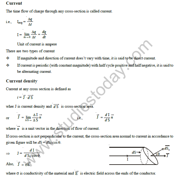
The time rate of flow of charge through any cross-section is called current.
i.e., \(I_{avg} = \dfrac{\Delta q}{\Delta t}\)
\[I = \lim_{\Delta t\to 0}\frac{\Delta q}{\Delta t} = \frac{dq}{dt}\]
The unit of current is the ampere.
There are two types of current:
- If the magnitude and direction of the current do not vary with time, it is said to be direct current.
- If the current is periodic (with constant magnitude) with half cycle positive and half negative, it is said to be alternating current.
Current density
Current at any cross-section is defined as \(i = \int \vec{J}\cdot d\vec{S}\), where \(\vec{J}\) is the current density and \(d\vec{S}\) is the cross-section area.
or \(\vec{J} = \lim_{\Delta S\to 0}\dfrac{\Delta I}{\Delta S}\,\hat{n}\), i.e., \(\vec{J} = \dfrac{dI}{dS}\,\hat{n}\), where \(\hat{n}\) is a unit vector in the direction of flow of current.
If the cross-section is not perpendicular to the current, the cross-section area normal to the current, in accordance with the given figure, will be \(dS = dS_0\cos\theta\).
\[\Rightarrow\ J = \frac{dI}{dS_0\cos\theta}\]
Also, \(\vec{J} = \sigma\vec{E}\), where \(\sigma\) is the conductivity of the material and \(\vec{E}\) is the electric field across the ends of the conductor.
Drift velocity
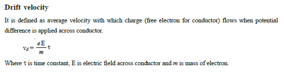
It is defined as the average velocity with which charge (free electrons for a conductor) flows when a potential difference is applied across the conductor.
\[v_d = \frac{eE}{m}\,\tau\]
where \(\tau\) is the relaxation time, \(E\) is the electric field across the conductor and \(m\) is the mass of an electron.
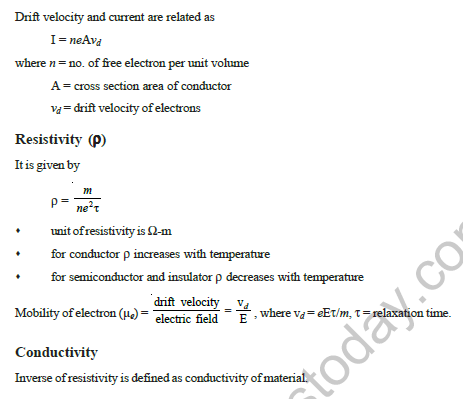
Drift velocity and current are related as \(I = neAv_d\), where \(n\) = number of free electrons per unit volume, \(A\) = cross-section area of the conductor, \(v_d\) = drift velocity of electrons.
Resistivity (\(\rho\))
\[\rho = \frac{m}{ne^2\tau}\]
- The unit of resistivity is \(\Omega\)-m.
- For a conductor, \(\rho\) increases with temperature.
- For a semiconductor and an insulator, \(\rho\) decreases with temperature.
Mobility of electron (\(\mu_e\)) = drift velocity / electric field = \(\dfrac{v_d}{E}\), where \(v_d = eE\tau/m\), \(\tau\) = relaxation time.
Conductivity
The inverse of resistivity is defined as the conductivity of the material.
Electric Circuit
An electric circuit consists of active and passive elements. An active element like a cell, battery or power supply provides current and electrical energy to an electric circuit. The passive elements like resistor (R), capacitor (C) and inductor (L) consume or store the electrical energy. A resistor opposes the flow of current. A capacitor C offers a low resistance to the flow of alternating current and does not allow direct current to pass through it at steady state. Energy stored in a capacitor, \(U = \tfrac{1}{2}CV^2 = \dfrac{Q^2}{2C}\). An inductor L opposes the variations of current and it does not oppose steady or direct current. The energy stored in an inductor is \(U = \tfrac{1}{2}LI^2\).
Ohm’s Law
Ohm’s law states that the ratio of the potential difference V maintained across a conductor to the current flowing through the conductor is a constant, which is equal to the resistance of the conductor, provided the physical conditions remain unchanged. If V is the potential difference in volts and the current I is in amperes, the electrical resistance is measured in ohms in the S.I. units.
i.e., \(\dfrac{V}{I} = R\)
Resistance
The resistance R of a material is given by
\[R = \frac{\rho\,l}{A}\]
where \(l\) is the length and \(A\) is the area of cross-section of the conducting body of resistance R. The resistance of most of the conductors increases with an increase in temperature, whereas the resistance of a few materials decreases with temperature. In the case of some of the conductors, the resistivity changes linearly with the increase of temperature. If \(\rho_0\) is the resistivity at a lower temperature \(T_0\) and \(\rho\) is the resistivity at a higher temperature \(T\), then
\[\rho = \rho_0\left[1+\alpha(T-T_0)\right]\]
where \(\alpha\) is called the temperature coefficient of resistivity. For semiconductors and insulators, resistance decreases with an increase in temperature.
Resistances in series
If a number of resistances \(R_1, R_2, R_3, \ldots, R_n\) are connected in series to a battery of e.m.f. E, the same current will pass through all the resistances. The equivalent or effective resistance \(R_{series}\) for such resistances is equal to the sum of all resistances.
\[R_{series} = R_1+R_2+\cdots+R_n\]
The same current I flows through each resistance, and the potential drops add up: \(V = V_1+V_2+\cdots+V_n\).
Resistances in parallel
A parallel combination of resistances can be made by connecting one end of all resistances to the positive terminal of the battery and the second end of all resistances to the negative terminal of the battery. The potential difference across all the resistances is the same, whereas the current I in the main circuit divides itself across the respective resistances \(R_1, R_2, R_3, \ldots, R_n\) as \(I_1, I_2, I_3, \ldots, I_n\), so that
\[I = I_1+I_2+I_3+\cdots+I_n\]
The equivalent or effective resistance in parallel \(R_{eq}\) is given by
\[\frac{1}{R_{eq}} = \frac{1}{R_1}+\frac{1}{R_2}+\frac{1}{R_3}+\cdots+\frac{1}{R_n}\]
Electromotive Force and Potential Difference
If a battery of e.m.f. E volts and internal resistance r ohm is connected to an external resistance R ohm, the current I flows throughout the circuit.
\[E = IR+Ir\]
The potential difference across the external resistance R is less than the e.m.f. of the cell. This potential difference across R, when the current is flowing through it, is called the closed circuit voltage. It is less than the e.m.f. of the cell, which is the potential difference when no current flows through the battery. Terminal potential difference across \(R = IR = E-Ir\).
Maximum power transfer
If a cell of e.m.f. E and internal resistance r is connected to a load resistance R, the current is \(I = \dfrac{E}{R+r}\).
\[\text{Electric power } P = I^2R = \frac{E^2R}{(R+r)^2}\]
For maximum power transfer,
\[\frac{dP}{dR} = 0\ \text{ or }\ \frac{d}{dR}\left[\frac{E^2R}{(R+r)^2}\right] = E^2\left[\frac{1}{(R+r)^2}-\frac{2R}{(R+r)^3}\right] = 0\ \text{ or }\ R = r\]
For \(R = r\), \(\dfrac{d^2P}{dR^2} < 0\) \(\Rightarrow\) P is maximum. i.e., the power transferred is maximum when the load resistance is equal to the internal resistance of the cell.
Grouping of Cells
Series Combination
If n cells are connected in series, as shown in the figure, they can be replaced by a single cell of e.m.f. E and resistance r, given by
\[E = E_1+E_2+\cdots+E_n \quad\text{and}\quad r = r_1+r_2+\cdots+r_n\]
Parallel Combination
If m cells are connected in parallel as shown in the figure, then their equivalent cell of e.m.f. E and internal resistance r is given by
\[E = \frac{\dfrac{E_1}{r_1}+\dfrac{E_2}{r_2}+\cdots+\dfrac{E_m}{r_m}}{\dfrac{1}{r_1}+\dfrac{1}{r_2}+\cdots+\dfrac{1}{r_m}}\qquad\text{and}\qquad \frac{1}{r} = \frac{1}{r_1}+\frac{1}{r_2}+\cdots+\frac{1}{r_m}\]
Series and Parallel Grouping of Cells
Suppose there are N identical cells, each of e.m.f. E and internal resistance r, grouped together to form an arrangement as shown in the figure. In each branch there are n cells in series and there are m such branches in parallel. The group of cells is joined across an external resistor R. Since the total number of cells is N, therefore \(N = mn\).
The equivalent cell of the group has the e.m.f. \(E_0 = nE\) and internal resistance \(r_0 = \dfrac{n}{m}r\). Thus, the total current flowing through the external resistor R is
\[I = \frac{E_0}{r_0+R} = \frac{nE}{\dfrac{nr}{m}+R}\quad\text{or}\quad I = \frac{mnE}{nr+mR}\]
Condition for Maximum Current through the External Resistance R.
- For maximum current through R, we must have \(nr = mR\), or \(\dfrac{m}{n} = \dfrac{r}{R}\).
- The maximum current is given by \(I_{max} = \dfrac{nE}{2R} = \dfrac{mE}{2r} = \dfrac{E}{2}\sqrt{\dfrac{mn}{rR}}\).
Wheatstone’s bridge
If a network of four resistances \(R_1, R_2, R_3\) and \(R_4\) is connected along arms AB, BC, AD and CD, and ends A and C are connected across the terminals of a battery, so that the galvanometer connected across B and D does not show any deflection, i.e. the potential at points B and D is equal, such an arrangement is called a balanced Wheatstone’s bridge, for which current \(I_1\) flows across ABC and \(I_2\) flows across ADC.
\(\therefore\ I_1R_1 = I_2R_3\) and \(I_1R_2 = I_2R_4\)
\[\text{or}\quad \frac{R_1}{R_2} = \frac{R_3}{R_4}\quad\text{or}\quad \frac{R_1}{R_3} = \frac{R_2}{R_4}\]
Kirchhoff’s Law
If an electrical circuit has more than one closed path, it is called a network. The electric currents in different portions of such electric circuits can be found by the application of the following Kirchhoff’s laws:
Kirchhoff’s First Law of Current: The algebraic sum of currents at any junction in a circuit is zero. It implies that the sum of the currents entering any junction is equal to the sum of the currents leaving that junction. At junction O, \(I_1+I_2+I_3-I_4-I_5-I_6 = 0\).
Kirchhoff’s Voltage Law (KVL): Around any closed circuit loop, the sum of voltage changes (drops or gains) across all the circuit elements while traversing in one direction (clockwise or anticlockwise) must be zero.
- While moving from higher potential to lower potential while crossing an element, in applying Kirchhoff’s second law, the P.D. is taken as negative.
Potentiometer
- A potentiometer consists of a uniform wire of large length of 4 m, 6 m, 8 m, etc.
- The potential drop across the potentiometer wire is directly proportional to its length (this is because the wire is of uniform area of cross-section).
- Through the path of the galvanometer, the current from the battery of e.m.f. E can be varied, i.e. if point D is closer to point A, less current flows through the path of the galvanometer; and if point D is farther from point A, then more current flows through the path of the galvanometer.
- For comparing e.m.f.s of two cells: the positive terminals of both the cells and the positive terminal of the battery (of e.m.f. E) are connected to the same end A of the potentiometer wire. Now, we locate point D on the potentiometer wire so that no current flows through the path of the galvanometer. Then [see figure (ii)] e.m.f. of cell = P.D. across A and D on the potentiometer wire …(i). For two cells, \(\dfrac{E_1}{E_2} = \dfrac{AD_1}{AD_2} = \dfrac{l_1}{l_2}\) …(ii)
- For finding the internal resistance (r) of a cell: (i) We connect a cell [see figure (iii)] and locate a point \(D_1\) on the potentiometer wire so that no current flows through the path of the galvanometer, when key \(K_2\) is not used. (ii) Now, we take out some resistance R from the resistance box (R.B.) and use key \(K_2\) also, and locate a point \(D_2\) on the potentiometer wire so that no current flows through the path of the galvanometer. Then \(r = R\left[\dfrac{l_1}{l_2}-1\right]\), where \(l_1\) = length \(AD_1\) of the potentiometer wire and \(l_2\) = length \(AD_2\) of the potentiometer wire.
Converting a Galvanometer into an Ammeter and Voltmeter
In a galvanometer, a moving coil is placed in a uniform magnetic field. When the current to be measured is passed through the coil of a galvanometer, the coil is deflected through a certain angle depending upon the current. The current I can be measured by converting a galvanometer into an ammeter by connecting a small resistance \(R_s\) in parallel to the galvanometer of resistance \(R_g\), through which the current \(I_g\) is flowing.
\[R_s = \frac{I_g}{I-I_g}\times R_g\]
The potential difference V between any two points A and B is measured by connecting a voltmeter across these points. A galvanometer is converted into a voltmeter by connecting a high resistance R in series with a galvanometer of resistance \(R_g\).
\[\frac{V_g}{R_g} = \frac{V-V_g}{R}\]
Heating Effects of Current
If a current I ampere passes through a heating element of resistance R for time t when a potential difference V volt is applied across it, the power produced is P.
\[P = VI = I^2R = \frac{V^2}{R}\]
Electrical energy or work = \(VIt\) J
Heat produced \(H = \dfrac{\text{Work}}{J} = \dfrac{VIt}{J}\) cal, where Joule’s constant \(J = 4.18\) joule/calorie (taken as 4.2 in the next step).
\[H = \frac{VIt}{4.2} = 0.24\,VIt = \frac{0.24\,V^2t}{R}\ \text{calorie}\]
1 kilowatt hour = \(1000\times60\times60 = 3.6\times10^6\) joule.
Fuse Wire
It is used in series with electrical installations to protect them from high electric current; this fuse melts, causing a break in the circuit when a high electric current flows. A fuse wire has high resistance and a low melting point; it is generally prepared from a tin-lead alloy (63% tin + 37% lead).
Free study material for Physics
CBSE Class 12 Physics Study Material: Chapter 01 Electric Charges and Fields
Essential Notes for Class 12 Physics
Explore essential learning tools for Class 12 Physics Chapter 01 Electric Charges and Fields. This curated collection features in-depth notes and targeted practice questions built around the active 2026 curriculum to streamline your daily revision.
Verified Solutions for Class 12 Physics
Built using official NCERT guidelines for Class 12 Physics, these materials provide reliable academic support. Integrating past examination questions and step-by-step solutions helps students understand official CBSE grading criteria.
Enhance Accuracy with Online Tests
Maximize your grade potential by utilizing Class 12 Physics practice papers in tandem with these structured notes. All printable assignments and interactive mock tests on our platform are updated for the 2026 session and available free of charge.
FAQs
Our advanced study package for Chapter 01 Electric Charges and Fields includes detailed concepts, diagrams, Mind Maps, and explanation of complex topics to ensure Class 12 students learn as per syllabus for 2026 exams.
The Mind Maps provided for Chapter 01 Electric Charges and Fields act as visual anchors which will help faster recall during high-pressure exams.
Yes, teachers use our Class 12 Physics resources for lesson planning as they are in simple language and have lot of solved examples.
Yes, You can download the complete, mobile-friendly PDF of the Physics Chapter 01 Electric Charges and Fields advanced resources for free.
Yes, our subject matter experts have updated the Chapter 01 Electric Charges and Fields material to align with the rationalized NCERT textbooks and have removed deleted topics and added new competency-based questions.