

Download CBSE Class 12 Physics Useful Resources
Explore structured advanced study materials through the CBSE Class 12 Physics Electric Circuits Basic Problems. Tailored for Class 12 learners, utilizing these Physics resources ensures thorough preparation and strengthens foundational knowledge before final CBSE evaluations.
Access CBSE Study Guides and Summaries
View or download the dedicated CBSE Class 12 Physics Electric Circuits Basic Problems resource below. Engaging with these advanced study guides under focused conditions ensures continuous academic progress and mastery of the 2026-27 curriculum for Chapter 01 Electric Charges and Fields.
CBSE Class 12 Physics Electric Circuits Basic Problems. Please refer to the examination notes which you can use for preparing and revising for exams. These notes will help you to revise the concepts quickly and get good marks.
CLASS 12 PHYSICS : ELECTRIC CIRCUITS
BASIC PROBLEMS
1. Two cells E1 and E2, having e.m.f. 4 V and 8 V and internal resistance 0.5 Ω and 1 Ω respectively are connected as shown. Find the current in each resistor and potential difference across each cell.

[Figure: Circuit with cells E1 (4 V) and E2 (8 V) in the top branch; the left branch has a 4.5 Ω resistor carrying current I; at junction M the current divides into I1 through the 3 Ω resistor and I2 through the 6 Ω resistor, both joining the right side of the loop]
Answer:
1. The two cells are connected in opposition, so the net e.m.f. in the loop = 8 - 4 = 4 V.
2. Net resistance of the loop = 0.5 + 1 + 4.5 + (3 × 6)/(3 + 6) = 0.5 + 1 + 4.5 + 2 = 8 Ω.
3. Current in the 4.5 Ω resistor, I = 4/8 = 0.5 A.
4. The 0.5 A divides in the ratio 6 : 3 between the 3 Ω and 6 Ω resistors, so I1 = \( \frac{1}{3} \) A and I2 = \( \frac{1}{6} \) A.
5. E2 is discharging: V2 = 8 - (0.5)(1) = 7.5 V.
6. E1 is being charged: V1 = 4 + (0.5)(0.5) = 4.25 V.
Teacher's Note:
a) In a loop of opposing cells, the larger e.m.f. drives the current and the smaller cell is charged.
b) Terminal voltage is E - Ir for a discharging cell but E + Ir for a cell being charged; do not use E - Ir for both.
2. A galvanometer having 30 divisions has a current sensitivity of 20 μA per division and a resistance of 25 ohm. Find the shunt required to convert it into an ammeter of 1 ampere range. Find the resistance which should be connected in series to convert this ammeter into a voltmeter of range 1 V.
Answer:
1. Full-scale current of the galvanometer, Ig = 30 × 20 μA = 600 μA = 6 × 10⁻⁴ A.
2. Shunt, S = \( \frac{I_g G}{I - I_g} \) = \( \frac{6 \times 10^{-4} \times 25}{1 - 6 \times 10^{-4}} \) ≈ 0.015 Ω.
3. Resistance of the ammeter, RA = \( \frac{G S}{G + S} \) ≈ 0.015 Ω.
4. For a 1 V voltmeter, total resistance = \( \frac{V}{I} \) = \( \frac{1}{1} \) = 1 Ω.
5. Series resistance required = 1 - 0.015 = 0.985 Ω.
Teacher's Note:
a) A shunt is connected in parallel to the galvanometer; a high resistance is connected in series to make a voltmeter.
b) Use the ammeter range (1 A), not the galvanometer current, when finding the voltmeter resistance in the second part.
c) Check: the series resistor is almost equal to the total resistance because the ammeter resistance is tiny.
3. A heater is designed to operate with a power of 1000 watts in a 100-volts line. It is connected, in combination with a resistance of 10 ohms and a resistance R, to a 100-volts mains as shown in the figure. What should be the value of R so that the heater operates with a power of 62.5 watts?

[Figure: A 10 Ω resistor in series with a parallel combination of the heater and the resistance R, connected across the 100 V mains]
Answer:
1. Resistance of the heater, Rh = V²/P = (100)²/1000 = 10 Ω.
2. For a power of 62.5 W, Ih² × 10 = 62.5, so Ih = 2.5 A.
3. Potential difference across the heater (and across R) = 2.5 × 10 = 25 V.
4. Potential difference across the series 10 Ω resistor = 100 - 25 = 75 V, so the total current = 75/10 = 7.5 A.
5. Current through R = 7.5 - 2.5 = 5 A.
6. R = 25/5 = 5 Ω.
Teacher's Note:
a) The heater and R are in parallel, and this combination is in series with the 10 Ω resistor.
b) The rated 1000 W applies only at 100 V; at other voltages find the heater resistance first and use it.
4. In the circuit shown a voltmeter reads 30 volts when it is connected across the 400 ohms resistance. Calculate what the same voltmeter will read when it is connected across the 300 ohm resistance ?
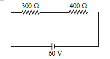
[Figure: A 300 Ω resistor and a 400 Ω resistor in series with a 60 V battery]
Answer:
1. Let the voltmeter resistance be Rv. With the voltmeter across the 400 Ω resistor, the reading is 30 V, so the voltage across the 300 Ω resistor = 60 - 30 = 30 V.
2. Current through the 300 Ω resistor = 30/300 = 0.1 A.
3. The parallel combination of 400 Ω and Rv has 30 V across it and carries 0.1 A, so its resistance = 300 Ω.
4. \( \frac{400 R_v}{400 + R_v} \) = 300, which gives Rv = 1200 Ω.
5. With the voltmeter across the 300 Ω resistor, the parallel resistance = \( \frac{300 \times 1200}{300 + 1200} \) = 240 Ω.
6. Total resistance = 240 + 400 = 640 Ω and the current = 60/640 A.
7. Voltmeter reading = 240 × \( \frac{60}{640} \) = 22.5 V.
Teacher's Note:
a) A real voltmeter draws current, so its resistance must first be found from the given reading.
b) The printed answer 21.4 V is not correct; the correct reading is 22.5 V.
c) Check: with the meter removed the p.d. across 300 Ω is about 25.7 V, so a reading of 22.5 V is reasonable for a meter of finite resistance.
5. A galvanometer of unknown resistance in series is connected across two identical cells each of 1.5 volt. When the cells are connected in series, the galvanometer records a current of 1 A and when the cells are in parallel, the current is 0.6 A. Find the internal resistance of the cell.
Answer:
1. Let the galvanometer resistance be G and the internal resistance of each cell be r.
2. Cells in series: \( \frac{3}{G + 2r} \) = 1, so G + 2r = 3.
3. Cells in parallel: \( \frac{1.5}{G + \frac{r}{2}} \) = 0.6, so G + 0.5r = 2.5.
4. Subtracting, 1.5r = 0.5, so r = \( \frac{1}{3} \) ≈ 0.33 Ω.
Teacher's Note:
a) Two identical cells in parallel have e.m.f. 1.5 V and internal resistance r/2.
b) Form two equations in G and r and subtract to eliminate G.
6. Determine the charge and energy stored in the capacitor in the figure for the circuit in which internal resistance of battery, r = 4Ω. Also, find the value of r for which the charge on the capacitor is zero.
[Figure: A bridge circuit: a battery of 6 V with internal resistance r on the left is connected to the top and bottom corners of a diamond. The upper-left arm is a 3 Ω resistor R, the upper-right arm is a 2 Ω resistor P, the lower-left arm is a 7 Ω resistor S and the lower-right arm is a resistor Q of resistance r. A 3 μF capacitor joins the left and right corners of the diamond]
Answer:
1. Resistance of branch R-S side: 3 + 7 = 10 Ω; resistance of branch P-Q side: 2 + 4 = 6 Ω. These are in parallel.
2. The 4 Ω is the resistance r of arm Q and the battery is treated as ideal, so the potential difference across each branch = 6 V.
3. Current in the 3 Ω-7 Ω branch = \( \frac{6}{10} \) = 0.6 A.
4. Potential drop across 7 Ω = 0.6 × 7 = 4.2 V.
5. Current in the 2 Ω-4 Ω branch = \( \frac{6}{6} \) = 1 A, so the potential drop across the 4 Ω resistor Q = 4 V.
6. Potential difference across the capacitor = 4.2 - 4 = 0.2 V.
7. Charge Q = CV = 3 μF × 0.2 V = 0.6 μC.
8. Energy = \( \frac{1}{2} \) CV² = \( \frac{1}{2} \) × 3 × 10⁻⁶ × (0.2)² = 6 × 10⁻⁸ J.
9. The charge is zero when the bridge is balanced: \( \frac{3}{7} \) = \( \frac{2}{r} \), so r = \( \frac{14}{3} \) ≈ 4.67 Ω.
Teacher's Note:
a) The capacitor carries no current in the steady state, so treat the circuit as two parallel branches and find the potentials of its two plates.
b) The battery is treated as ideal and r = 4 Ω is the resistance of arm Q, which gives the printed answer of 0.6 μC and 6 × 10⁻⁸ J.
c) The condition for zero charge is the balanced-bridge condition, which does not depend on the internal resistance.
7. A battery of e.m.f. 10 V is connected to a network of resistors as shown in the figure. The potential difference across a resistor of 400 Ω is measured by a voltmeter of resistance 400 Ω. Find the reading of the volt meter.
[Figure: Battery of 10 V connected between A and D. Resistors: 100 Ω between A and B, 100 Ω between B and C, 100 Ω between A and C, 200 Ω between C and D, and a 400 Ω resistor joined between B and D with a voltmeter V of resistance 400 Ω connected across it]
Answer:
1. The 400 Ω resistor and the 400 Ω voltmeter are in parallel, so their combined resistance = 200 Ω between B and D.
2. Let the potentials be VA = 10 V and VD = 0. Resistors: A-B 100 Ω, B-C 100 Ω, A-C 100 Ω, C-D 200 Ω, B-D 200 Ω.
3. At node B: \( \frac{10 - V_B}{100} \) + \( \frac{V_C - V_B}{100} \) = \( \frac{V_B}{200} \).
4. At node C: \( \frac{10 - V_C}{100} \) + \( \frac{V_B - V_C}{100} \) = \( \frac{V_C}{200} \).
5. Solving, VB = VC = \( \frac{20}{3} \) V.
6. The voltmeter reads VB - VD = \( \frac{20}{3} \) V ≈ 6.67 V.
Teacher's Note:
a) A voltmeter of finite resistance is treated as a resistor in parallel with the element it measures.
b) Apply Kirchhoff's junction rule at B and C; here B and C turn out to be at the same potential.
8. A battery of internal resistance 4 Ω is connected to the one single network of resistances as shown in the figure.
(a) Find the value of R so that maximum power is delivered to the network.
(b) Find the maximum power.
[Figure: A battery E with internal resistance 4 Ω feeds a network. Top row: wire to a node, then R, then a node, then R, then the right corner. Vertical arms: R on the left, 6R in the middle, R on the right. Bottom row: R between the left and middle nodes, 4R between the middle node and the right node; the bottom wire returns to the battery]
Answer:
1. The left vertical R and the bottom-left R are in series, so the path from the top-left node to the base of the 6R arm is 2R.
2. The potentials at the two ends of the 6R arm are equal (the bridge is balanced), so no current flows in 6R and it can be ignored.
3. The top-left R is in parallel with 2R, giving \( \frac{2R}{3} \). The top-right R and the right vertical R are in series (2R), and this is in parallel with 4R, giving \( \frac{4R}{3} \).
4. Network resistance = \( \frac{2R}{3} \) + \( \frac{4R}{3} \) = 2R.
5. (a) Maximum power is delivered when the network resistance equals the internal resistance: 2R = 4 Ω, so R = 2 Ω.
6. (b) Current at maximum power, I = \( \frac{E}{4 + 4} \) = \( \frac{E}{8} \).
7. Pmax = I² × 4 = \( \frac{E^{2}}{64} \) × 4 = \( \frac{E^{2}}{16} \) watt.
Teacher's Note:
a) Maximum power transfer occurs when external resistance equals internal resistance.
b) Take care in the network reduction: the 6R arm is joined between two nodes that end up at the same potential only after solving the whole network, so use node potentials rather than guessing.
9. In the circuit shown in the figure, the e.m.f. of the cell is 1.8 V and its internal resistance r is \( \frac{2}{3} \) Ω. Find the current in 3Ω resistance and power consumed by the circuit from the battery when K is closed.
[Figure: A rectangle with a 3 Ω resistor on the top side and a 6 Ω resistor on the bottom side; inside, two diagonals cross at the centre, with an 8 Ω resistor in the upper-left, 4 Ω in the upper-right, 2 Ω in the lower-left and 6 Ω in the lower-right. The left side and right side of the rectangle are wires connected through a cell E with internal resistance r and a key K]
Answer:
1. The left side wires join the upper-left and lower-left corners at node A, and the right side wires join the upper-right and lower-right corners at node B.
2. Between A and B: 8 Ω and 2 Ω in parallel give 1.6 Ω; 4 Ω and 6 Ω in parallel give 2.4 Ω; these are in series, giving 4 Ω.
3. This 4 Ω is in parallel with 3 Ω and 6 Ω (the top and bottom resistors), and the 3 Ω and 6 Ω together give 2 Ω, so RAB = \( \frac{4 \times 2}{4 + 2} \) = \( \frac{4}{3} \) Ω.
4. Total resistance = \( \frac{4}{3} \) + \( \frac{2}{3} \) = 2 Ω, so the current from the cell = \( \frac{1.8}{2} \) = 0.9 A.
5. Potential difference across AB = 0.9 × \( \frac{4}{3} \) = 1.2 V.
6. Current in the 3 Ω resistance = \( \frac{1.2}{3} \) = 0.4 A.
7. Power drawn from the battery = EI = 1.8 × 0.9 = 1.62 W.
Teacher's Note:
a) Identify nodes first: wires of zero resistance make several corners the same node.
b) Power consumed from the battery is EI, which includes the loss in the internal resistance.
10. Two resistors, 400 ohms and 800 ohms, are connected in series with a 6-volt battery. It is desired to measure current in the circuit. An ammeter of 10 ohms resistance is used for this purpose. What will be the reading in the ammeter ? Similarly, if a voltmeter of 10,000 ohms resistance is used to measure the potential difference across the 400-ohm resistor, what will be the reading in the voltmeter ?
Answer:
1. Ammeter in series: total resistance = 400 + 800 + 10 = 1210 Ω.
2. Ammeter reading = \( \frac{6}{1210} \) = 4.96 × 10⁻³ A.
3. Voltmeter across the 400 Ω resistor: parallel resistance = \( \frac{400 \times 10000}{400 + 10000} \) ≈ 384.6 Ω.
4. Total resistance = 384.6 + 800 = 1184.6 Ω, so the current = \( \frac{6}{1184.6} \) ≈ 5.065 × 10⁻³ A.
5. Voltmeter reading = 384.6 × 5.065 × 10⁻³ ≈ 1.95 V.
Teacher's Note:
a) An ideal ammeter has zero resistance and an ideal voltmeter has infinite resistance; real meters change the circuit slightly.
b) The true values without meters are 4.98 × 10⁻³ A and 2 V, so the meter readings are slightly lower.
11. A carbon and an aluminium wire are connected in series. If the combination has resistance of 30 ohm at 0°C, what is the resistance of each wire at 0°C so that the resistance of the combination does not change with temperature? [αC = -0.5 × 10⁻³ (C°)-1 and αA = 4 × 10⁻³ (C°)-1]
Answer:
1. Let the resistances at 0°C be RC and RA, so RC + RA = 30.
2. The combination does not change with temperature if the total change is zero: RCαC + RAαA = 0.
3. RC(-0.5 × 10⁻³) + RA(4 × 10⁻³) = 0, so RC = 8RA.
4. 9RA = 30, so RA = \( \frac{10}{3} \) Ω and RC = \( \frac{80}{3} \) Ω.
Teacher's Note:
a) Carbon has a negative temperature coefficient, so its resistance falls as temperature rises and can cancel the rise of the metal.
b) Check: \( \frac{80}{3} \) + \( \frac{10}{3} \) = 30 Ω.
12. The temperature of water in a tap is 22ºC. It is required to draw a continuous supply of water at the temperature of human body (98.6ºF) flowing at the rate of 1 litre per minute.
(i) Find the power which will be consumed by a heater coil placed in the path of water.
(ii) Find the current flowing in the heater coil if the supply voltage is 210 V.
Answer:
1. Body temperature 98.6°F = \( \frac{5}{9} \) (98.6 - 32) = 37°C, so the rise in temperature = 37 - 22 = 15°C.
2. Mass of water per second = 1 kg per 60 s = \( \frac{1}{60} \) kg/s.
3. (i) Power = m c ΔT = \( \frac{1}{60} \) × 4200 × 15 = 1050 W (1050 J/s).
4. (ii) Current I = \( \frac{P}{V} \) = \( \frac{1050}{210} \) = 5 A.
Teacher's Note:
a) Convert Fahrenheit to Celsius before finding the temperature rise.
b) 1 litre of water has a mass of 1 kg; use the specific heat 4200 J/kg°C.
13. In the diagram shown, find the potential difference between the points A and B and between the points B and C in the steady state.
[Figure: A capacitor network between points A and C with a 100 V battery and a 20 Ω resistor between A and the battery and a 10 Ω resistor between the battery and C. Top line from A: a 3 μF capacitor, then the junction B, then a 3 μF capacitor, then the right vertical wire to C. A 3 μF capacitor joins the top line (between the first 3 μF capacitor and B) to the middle line, and a 1 μF capacitor joins the top line (between B and the second 3 μF capacitor) to the middle line. The middle line from the left vertical wire at A to the right vertical wire at C carries a 1 μF capacitor between these two junctions]
Answer:
1. In the steady state no current flows through the capacitors, so no current flows through the 20 Ω and 10 Ω resistors, and the p.d. across the capacitor network between A and C is 100 V.
2. Between A and B: the 3 μF capacitor in the top-left arm and the 3 μF capacitor below it are in parallel, giving 6 μF.
3. Between B and C: the 3 μF capacitor in the top-right arm and the 1 μF capacitor below it are in parallel, giving 4 μF. The 1 μF capacitor in the middle connects A and C directly and does not affect the division.
4. The 6 μF and 4 μF are in series, carrying the same charge, so VAB = \( \frac{4}{6 + 4} \) × 100 = 40 V.
5. VBC = \( \frac{6}{6 + 4} \) × 100 = 60 V.
Teacher's Note:
a) In a series combination of capacitors the charge is the same, so the voltage divides inversely as the capacitance.
b) The printed answer 25 V and 75 V is not correct for the circuit as drawn; the correct values are 40 V and 60 V.
c) Resistors in series with capacitors carry no current in the steady state, so there is no potential drop across them.
14. A part of circuit is in a steady state along with the currents flowing in the branches, the values of resistances, etc. is shown in the figure. Calculate the energy stored in the capacitor C (4μF).
[Figure: A part of a circuit with two horizontal rails. Upper rail: a 4 V cell and 3 Ω resistor carrying 2 A to a central junction, then a 5 Ω resistor, then a 1 Ω resistor going down to the lower rail. A 3 Ω resistor carries 1 A downward into the upper junction from above. Lower rail: a 3 V cell and 1 Ω resistor carrying 2 A to a central junction, then a 4 Ω resistor to the node joined by the 1 Ω resistor, then another 4 Ω resistor going out. A 3 Ω resistor carries 1 A upward into the lower junction from below. The 4 μF capacitor C joins the upper and lower central junctions]
Answer:
1. In the steady state the capacitor carries no current. The upper junction P receives 2 A from the left and 1 A from above, so 3 A flows through the 5 Ω and 1 Ω resistors on its right.
2. The lower junction Q receives 2 A from the left and 1 A from below, so 3 A flows through the 4 Ω resistor on its right.
3. Let the common right-hand node be R. Then VP - VR = 3 × (5 + 1) = 18 V and VQ - VR = 3 × 4 = 12 V.
4. Potential difference across the capacitor = 18 - 12 = 6 V.
5. Energy stored = \( \frac{1}{2} \) CV² = \( \frac{1}{2} \) × 4 × 10⁻⁶ × 36 = 72 × 10⁻⁶ J = 72 μJ.
Teacher's Note:
a) Apply the junction rule first, because the capacitor branch carries no current.
b) The printed answer 72 μC has the wrong unit; energy is measured in joules, so the correct answer is 72 μJ (the charge on the capacitor is 24 μC).
15. A cell of emf ε = 1.5 V and internal resistance r = 5 Ω is connected to a non-linear conductor in which current varies with voltage as V² = I. Calculate the current drawn from the cell and its terminal voltage.
Answer:
1. For the non-linear conductor, I = V², where V is the terminal voltage of the cell.
2. Terminal voltage V = ε - Ir = 1.5 - 5V².
3. 5V² + V - 1.5 = 0, so V = \( \frac{-1 + \sqrt{31}}{10} \) ≈ 0.457 V (the negative root is rejected).
4. Current I = V² ≈ 0.209 A.
Teacher's Note:
a) Use the terminal voltage in the relation I = V², and combine it with V = ε - Ir to get a quadratic.
b) The printed answer (1 A, 1 V) is obtained for r = 0.5 Ω (1 + 0.5 × 1 = 1.5); for the data as printed, r = 5 Ω, the values are about 0.21 A and 0.46 V.
c) Always reject the negative root of the quadratic, because the voltage across the conductor here is positive.
16. 2m long resistance wire of area of cross-section 0.5 mm2 has a resistance of 2.2 ohm. Calculate
(a) The specific resistance of the material of the wire.
(b) The length of the same wire which when connected in parallel with 2m wire will give a resistance of 2 ohm.
Answer:
1. (a) ρ = \( \frac{RA}{l} \) = \( \frac{2.2 \times 0.5 \times 10^{-6}}{2} \) = 5.5 × 10⁻⁷ Ω m.
2. (b) Let the resistance of the second piece be R2: \( \frac{2.2 R_2}{2.2 + R_2} \) = 2, so 0.2R2 = 4.4 and R2 = 22 Ω.
3. Resistance per metre of the wire = \( \frac{2.2}{2} \) = 1.1 Ω/m.
4. Length of the second piece = \( \frac{22}{1.1} \) = 20 m.
Teacher's Note:
a) Convert mm² to m² (1 mm² = 10⁻⁶ m²) before using ρ = RA/l.
b) The same wire means the same ρ and same area, so resistance is proportional to length.

Free study material for Physics
CBSE Class 12 Physics Study Material: Chapter 01 Electric Charges and Fields
Comprehensive Study Resources for Chapter 01 Electric Charges and Fields
Explore essential learning tools for Class 12 Physics Chapter 01 Electric Charges and Fields. This curated collection features in-depth notes and targeted practice questions built around the active 2026 curriculum to streamline your daily revision.
Understanding Marking Schemes
Each resource draws directly from authorized textbooks to maintain academic accuracy. Evaluating solved examples allows Class 12 students to master the formal presentation and answer-writing standards expected in upcoming school exams.
Complete Revision for Physics
Maximize your grade potential by utilizing Class 12 Physics practice papers in tandem with these structured notes. All printable assignments and interactive mock tests on our platform are updated for the 2026 session and available free of charge.
FAQs
Our advanced study package for Chapter 01 Electric Charges and Fields includes detailed concepts, diagrams, Mind Maps, and explanation of complex topics to ensure Class 12 students learn as per syllabus for 2026 exams.
The Mind Maps provided for Chapter 01 Electric Charges and Fields act as visual anchors which will help faster recall during high-pressure exams.
Yes, teachers use our Class 12 Physics resources for lesson planning as they are in simple language and have lot of solved examples.
Yes, You can download the complete, mobile-friendly PDF of the Physics Chapter 01 Electric Charges and Fields advanced resources for free.
Yes, our subject matter experts have updated the Chapter 01 Electric Charges and Fields material to align with the rationalized NCERT textbooks and have removed deleted topics and added new competency-based questions.