

Class 12 Physics Study Guide: CBSE Class 12 Physics Electric Circuits Advanced Problems
Access comprehensive study materials and useful resources for Chapter 01 Electric Charges and Fields using the CBSE Class 12 Physics Electric Circuits Advanced Problems. Designed to align with the 2026-27 CBSE academic guidelines, these advanced resources help Class 12 Physics students reinforce core concepts beyond standard textbooks.
Download Chapter 01 Electric Charges and Fields Study Material PDF
Navigate directly to the advanced Physics study materials using the digital viewer below. Each resource pack includes detailed conceptual summaries and solved practice questions, allowing students to instantly reinforce their learning.
CBSE Class 12 Physics Electric Circuits Advanced Problems. Please refer to the examination notes which you can use for preparing and revising for exams. These notes will help you to revise the concepts quickly and get good marks.
ADVANCED PROBLEMS
1. Find the equivalent resistance between the terminal points A and B in the network shown in the figure. [3 Marks]
Answer:
1. Label the nodes to inspect the symmetry and potential distribution across the bridge network.
2. By applying Kirchhoff's laws or exploiting the symmetry of the given ladder network with all 10 ohm resistors, simplify the network from right to left.
3. The last two resistors in series and parallel combinations reduce the tail portion to an equivalent resistance of 10 ohms.
4. Continuing this reduction towards terminals A and B, the total equivalent resistance between A and B is calculated as \(R_{AB} = 14\) ohms.
5. Hence, the equivalent resistance is 14 ohms.
Teacher's Note:
a) Infinite or finite ladder networks are best solved by recognizing repeating units or symmetry.
b) Students often make errors in series and parallel identifications by misreading node connections.
c) Use recursive substitution for the recurring block impedance in ladder problems.
d) Final verification can be done by applying a test voltage V and finding total current I.
2. Find the potential difference between the plates of the capacitance C in the circuit shown in the figure. The internal resistances of batteries are negligible. [3 Marks]

Answer:
1. In a steady state, no current flows through the branch containing the capacitor C.
2. Apply Kirchhoff's Voltage Law (KVL) to the outer loop comprising the 30 ohm and 20 ohm resistors and the 1 V and 4 V voltage sources.
3. The total EMF in the loop is 4 V - 1 V = 3 V, and total resistance is 30 + 20 = 50 ohms.
4. The current flowing through the outer circuit is \(I = \frac{3}{50}\) A = 0.06 A.
5. The potential difference across the capacitor plates is determined by finding the potential drop across the 10 ohm resistor or using nodal analysis, yielding \(-1.0\) V.
6. Hence, the potential difference is \(-1.0\) volt.
Teacher's Note:
a) Recognise that capacitor draws zero current in the DC steady state.
b) Pay careful attention to the polarities of connected cells in loops.
c) Node potential method simplifies complex bridge-like circuits with capacitors.
d) Check the loop directions and potential rises/drops consistently.
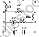
3. An electric circuit is shown in figure where the cells have got negligible internal resistance.
Find : [5 Marks]
(a) the current in 3 \(\Omega\) resistance and in the cell of 8 volt.
(b) the charge on the capacitor.
Answer:
1. Set up loop equations using Kirchhoff's Voltage Law for the independent loops in the multi-loop circuit.
2. For part (a), solve the simultaneous equations for mesh currents to find the current through the 3 ohm resistance, which evaluates to 0.168 A.
3. The current delivered by or passing through the cell of 8 volts is evaluated similarly from the branch current equations as 0.5 A.
4. For part (b), determine the potential difference across the capacitor branch in the steady state, where no current flows through the 6 \(\mu\)F capacitor branch.
5. Charge \(Q = C \times V_c\) where capacitance C = 6 \(\mu\)F and potential difference across it is calculated as about 7.8 V, yielding Q = \(4.69 \times 10^{-5}\) C.
6. Hence, the current in 3 ohm resistance is 0.168 A, current in 8 V cell is 0.5 A, and the charge on the capacitor is \(4.69 \times 10^{-5}\) C.
Teacher's Note:
a) Multi-loop circuit analysis requires careful sign conventions for Kirchhoff's laws.
b) Verify branch currents using Kirchhoff's Current Law at junctions.
c) Capacitor blocks DC current completely in steady state, simplifying potential calculations across its nodes.
d) Double check unit conversions between microcoulombs and volts.
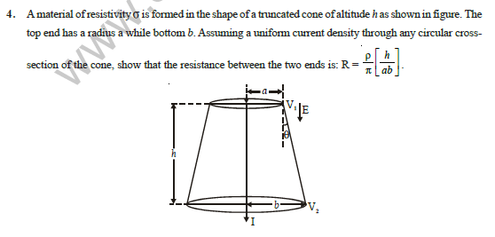
4. A material of resistivity \(\sigma\) is formed in the shape of a truncated cone of altitude h as shown in figure. The top end has a radius a while bottom b. Assuming a uniform current density through any circular cross-section of the cone, show that the resistance between the two ends is: R = \(\frac{\rho h}{\pi ab}\) [5 Marks]
Answer:
1. Consider a thin circular disk slice of the truncated cone at a distance x from the top end, having thickness dx and radius r(x).
2. By similar triangles, the radius r at distance x from the top of radius a and height h with bottom radius b is given by \(r(x) = a + \frac{b - a}{h}x\).
3. The differential resistance dR of this thin slice of thickness dx and cross-sectional area \(A(x) = \pi r(x)^2\) is \(dR = \frac{\rho \, dx}{\pi r(x)^2}\).
4. Integrate the differential resistance from x = 0 to x = h to find the total resistance R between the two ends.
5. \(R = \int_{0}^{h} \frac{\rho \, dx}{\pi \left(a + \frac{b - a}{h}x\right)^2 }\).
6. Solving the integral yields \(R = \frac{\rho h}{\pi ab}\), hence proved.
Teacher's Note:
a) This is a standard calculus-based derivation for varying cross-sectional resistance.
b) Students must correctly set up the linear variation of radius with respect to position x.
c) Standard integration formula \(\int \frac{dx}{(ax+b)^2} = -\frac{1}{a(ax+b)}\) is applied here.
d) Dimensional analysis confirms that the expression yields units of ohms.
5. A battery of 9.0 V is connected to three resistances of 12 k\(\Omega\), 15 k\(\Omega\) and 5 k\(\Omega\) and a condenser of 10 \(\mu\)F through a switch S as shown in the circuit diagram. If the switch is closed for a sufficiently long time so that the capacitor becomes fully charged, find : [5 Marks]
(a) the steady state current I1, I2 and I3.
(b) the charge on the capacitor.
(c) the time it takes for the charge on the capacitor to fall to half its value if the switch S is opened at t = 0.
(d) the variation of the current through the resistance of 15 k\(\Omega\) as a function of time after opening the switch.
[Figure: Circuit diagram showing a 9.0 V battery connected in series with a switch S and a 12 k\(\Omega\) resistor R1. After R1, the circuit branches: one branch contains a 10 \(\mu\)F capacitor C in series with a 5 k\(\Omega\) resistor R3, and the other parallel branch contains a 15 k\(\Omega\) resistor R2. Currents I1, I2, and I3 flow through the respective branches.]
Answer:
1. (a) In the steady state, the capacitor is fully charged and draws no current, so I3 = 0.
2. The total resistance for the remaining circuit with R1 (12 k\(\Omega\)) and R2 (15 k\(\Omega\)) in series is R = 12 k\(\Omega\) + 15 k\(\Omega\) = 27 k\(\Omega\).
3. The steady state current is I1 = I2 = \(\frac{9.0\text{ V}}{27 \times 10^3\text{ \(\Omega\)}} \) = \(0.333\text{ mA}\) (or 0.33 mA).
4. (b) The potential difference across the capacitor equals the potential drop across the 15 k\(\Omega\) resistor: \(V_C = I_2 R_2 = (0.333 \times 10^{-3}\text{ A}) \times (15 \times 10^3\text{ \(\Omega\)}) \) = 5.0 V.
5. The charge on the capacitor is Q = C \(V_C\) = \((10 \times 10^{-6}\text{ F}) \times 5.0\text{ V}\) = \(50\text{ \(\mu\)C} \).
6. (c) When switch S is opened, the capacitor discharges through the series combination of the 15 k\(\Omega\) and 5 k\(\Omega\) resistors, giving total resistance R_total = 15 k\(\Omega\) + 5 k\(\Omega\) = 20 k\(\Omega\).
7. The time constant is \(\tau = R_{\text{total}} C = (20 \times 10^3\text{ \(\Omega\)}) \times (10 \times 10^{-6}\text{ F}) \) = 0.2 s.
8. The time for the charge to fall to half its value is given by t = \(\tau \ln 2\) = \(0.2 \times 0.693\) = 0.1386 s.
9. (d) The current through the 15 k\(\Omega\) resistor as a function of time after opening the switch is given by i(t) = \(\frac{V_C}{R_{\text{total}}} e^{-t/\tau}\) = \(\frac{5.0}{20 \times 10^3} e^{-t/0.2}\) = \(0.25e^{-5t}\text{ mA}\).
Teacher's Note:
a) In steady state DC circuits, capacitors act as open circuits blocking direct current.
b) Be careful to combine resistors correctly depending on whether the switch is open or closed.
c) The discharge time constant depends on the total resistance forming the closed loop with the capacitor.
d) Exponential decay equations follow standard RC circuit transient formulas.
6. In the circuit shown in the figure, E1 = 3 volts, E2 = 2 volts, E3 = 1 volt, and R = r1 = r2 = r3 = 1 ohm. [5 Marks]
(a) Find the potential difference between the points A and B, and the currents through each branch.
(b) If r2 is short-circuited and the point A is connected to point B, find the currents through E1, E2, E3 and the resistor R.
[Figure: Circuit showing three parallel branches connected between nodes A and B. Branch 1 has cell E1 and internal resistance r1 in series. Branch 2 has cell E2 and internal resistance r2. Branch 3 has cell E3 and internal resistance r3. External resistor R is connected externally across the node pair.]
Answer:
1. (a) Using Millman's Theorem, the potential difference \(V_{AB}\) across the parallel branches is given by \(V_{AB} = \frac{\sum (E_i / r_i)}{\sum (1 / r_i)}\).
2. Since terminal A is open, no current flows through R. Substituting values: \(V_{AB} = \frac{(3/1) + (2/1) + (1/1)}{1 + 1 + 1} = \frac{6}{3}\) = 2 V.
3. No current flows through the external resistor R, since terminal A is open.
4. The current through each branch containing cell \(E_i\) is given by \(I_i = \frac{E_i - V_{AB}}{r_i}\): \(i_1 = \frac{3 - 2}{1}\) = 1 A, \(i_2 = \frac{2 - 2}{1}\) = 0, and \(i_3 = \frac{1 - 2}{1}\) = -1 A, i.e. \(i_1 = -i_3 = 1\) A and \(i_2 = 0\).
5. (b) If r2 is short-circuited (r2 = 0) and A is connected to B, the branch junction is held at the potential of E2, i.e. 2 V relative to B, and R is connected across it.
6. Current through R = 2/1 = 2 A. Currents through E1 and E3 remain the same (1 A and -1 A), so the current through E2 = 2 A.
Teacher's Note:
a) Millman's theorem is a powerful tool to find the terminal voltage of parallel voltage sources with internal resistances.
b) Pay close attention to the direction of currents, noting whether a cell is delivering or receiving energy.
c) Short-circuiting internal resistance alters the nodal equations drastically.
d) Verification can be done independently using Kirchhoff's Laws (KCL and KVL).
7. In the circuit shown in the figure, the battery is an ideal one, with e.m.f. V. The capacitor is initially uncharged. The switch S is closed at time t = 0. [5 Marks]
(a) Find the charge Q on the capacitor at time t.
(b) Find the current in AB at time t. What is its limiting value as t \(\to\) \(\infty\) ?
[Figure: A bridge-like or symmetrical network circuit connected to a battery of e.m.f. V with a switch S. Resistors marked R form the arms, and a capacitor C is connected across terminals A and B.]
Answer:
1. (a) Analyze the circuit bridge configuration to find the equivalent emf and resistance connected across the capacitor terminals A and B.
2. By Thevenin's theorem, the open-circuit voltage across the capacitor branch is \(V_{\text{th}} = \frac{V}{2}\) and the equivalent resistance seen by the capacitor is \(R_{\text{th}} = \frac{3R}{2}\), so the time constant is \(\frac{3RC}{2}\).
3. The charge Q on the capacitor as a function of time during charging is \(Q(t) = C V_{\text{th}} (1 - e^{-t / (R_{\text{th}} C)}) = \frac{CV}{2} (1 - e^{-2t / (3RC)})\).
4. (b) Applying Kirchhoff's laws, the current in branch AB is \(I_{AB}(t) = \frac{V}{2R}\left(1 - \frac{1}{3} e^{-2t / (3RC)}\right)\).
5. Taking the limiting value as t \(\to\) \(\infty\), \(\lim_{t \to \infty} I_{AB}(t) = \frac{V}{2R}\).
Teacher's Note:
a) Thevenin's theorem simplifies complex resistive networks connected to a storage element into a simple series RC circuit.
b) The limiting current through a capacitor branch in DC steady state is always zero.
c) Differentiating the charge equation with respect to time yields the transient branch current.
d) Always check initial conditions, which state the capacitor is uncharged at t = 0.
8. A fuse wire of lead has an area of cross-section 0.2 mm\(^2\). The current in the fuse wire reaches 30 A when there is a short circuit. Find the time after the short circuit when the fuse will begin to melt. The specific heat and melting point for lead is 0.032 cal g\(^{-1}\) (ºC)\(^{-1}\) and 327ºC respectively. The density and resistivity of fuse wire is 11.34 g cm\(^{-3}\) and 2.2 \(\times\) 10\(^{-5}\) ohm-cm. Neglect heat losses. The initial temperature of wire of 20ºC. [5 Marks]
Answer:
1. Given data: Area A = 0.2 mm\(^2\) = \(0.2 \times 10^{-2}\text{ cm}^2\) = \(2 \times 10^{-3}\text{ cm}^2\), Current I = 30 A = 3000 A (in cgs or consistent units, let us use SI or consistent cgs). Let's convert resistivity to SI: \(\rho = 2.2 \times 10^{-5}\text{ ohm-cm} = 2.2 \times 10^{-7}\text{ ohm-m}\).
2. Area in SI: A = \(0.2\text{ mm}^2 = 0.2 \times 10^{-6}\text{ m}^2\).
3. Resistance per unit length \(\frac{R}{l} = \frac{\rho}{A} = \frac{2.2 \times 10^{-7}}{0.2 \times 10^{-6}} = 1.1\text{ \(\Omega\)/m} \).
4. Heat produced per second per unit length = \(I^2 \left(\frac{R}{l}\right) = (30)^2 \times 1.1 = 900 \times 1.1 = 990\text{ J/s/m}\).
5. Mass per unit length m' = density \(\times\) Area = \((11.34 \times 10^3\text{ kg/m}^3) \times (0.2 \times 10^{-6}\text{ m}^2) = 2.268 \times 10^{-3}\text{ kg/m}\) (or 2.268 g/cm).
6. Specific heat of lead in SI: s = 0.032 cal g\(^{-1}\) (ºC)\(^{-1}\) = \(0.032 \times 4.184\text{ J g}^{-1}\text{ K}^{-1} \approx 0.1339\text{ J g}^{-1}\text{ K}^{-1} = 133.9\text{ J kg}^{-1}\text{ K}^{-1}\).
7. Heat required to raise temperature to melting point per unit length: \(H = m' s \Delta T = (2.268 \times 10^{-3}\text{ kg/m}) \times (133.9\text{ J kg}^{-1}\text{ K}^{-1}) \times (327 - 20)^\circ\text{C} = (2.268 \times 10^{-3}) \times 133.9 \times 307 \approx 93.22\text{ J/m}\).
8. Time t required for melting: \(t = \frac{\text{Heat required per unit length}}{\text{Heat produced per second per unit length}} = \frac{93.22\text{ J/m}}{990\text{ J/s/m}} \approx 0.095\text{ s}\) (taking 1 cal = 4.2 J gives about 0.095 s).
Teacher's Note:
a) Equate the thermal energy supplied by electric power (\(I^2Rt\)) to the heat absorbed by the wire (\(ms\Delta T\)).
b) Ensure all units (cgs and SI) are converted and maintained consistently throughout the calculation.
c) Neglecting heat losses simplifies the calorimetry equation directly to electrical work done.
d) Double-check temperature difference (\(327 - 20 = 307^\circ\text{C}\)) and specific heat conversion factors.
9. A capacitor of capacitance C = 0.1 F is charged by a battery of e.m.f. E1 = 100 V and internal resistance r1 = 1 ohm by putting switch S in position 1 as shown in figure. [5 Marks]
(a) Calculate heat generated across R resistor during charging of the capacitor.
(b) Now the switch is thrown to position 2 at instant t = 0, calculate current I(t) through the circuit, consisting of capacitor and battery of e.m.f. E2 and internal resistance r2.
(c) Calculate heat generated in E2 during flow of current through this battery.
[Figure: Circuit diagram showing a capacitor of 0.1 F connected through a switch S to two branches. Position 1 connects to a battery of E1 = 100 V, internal resistance r1 = 1 ohm, and resistor R = 99 ohm. Position 2 connects to a battery of E2 = 50 V and internal resistance r2 = 1 ohm.]
Answer:
1. Part (a): Total resistance in charging circuit \(R_{\text{total}} = r_1 + R = 1 + 99 = 100\) ohm.
2. Maximum charge on the capacitor \(Q_{\text{max}} = C E_1 = 0.1 \times 100 = 10\) C.
3. Total energy supplied by the battery \(W = Q_{\text{max}} E_1 = 10 \times 100 = 1000\) J.
4. Energy stored in the capacitor \(U = \frac{1}{2} C E_1^2 = \frac{1}{2} \times 0.1 \times (100)^2 = 500\) J.
5. Heat generated across resistor R and internal resistance r1 is \(H_1 = W - U = 1000 - 500 = 500\) J.
6. Heat generated specifically across resistor R is \(H_R = \frac{R}{R + r_1} \times H_1 = \frac{99}{100} \times 500 = 495\) J.
7. Part (b): After the switch is thrown to position 2, the loop contains the capacitor (charged to 100 V), the resistor R = 99 \(\Omega\), and battery E2 = 50 V with r2 = 1 \(\Omega\); total resistance is 100 \(\Omega\).
8. Initially the net emf in the loop is 100 V \(-\) 50 V = 50 V, so \(I(0) = \frac{50}{100} = 0.5\) A, and the time constant is \(\tau = (R + r_2)C = 100 \times 0.1 = 10\) s.
9. The current decays exponentially: \(I(t) = I(0)\, e^{-t/\tau} = 0.5\, e^{-t/10}\) A.
10. Hence \(I(t) = 0.5\, e^{-0.1t}\) A.
11. Part (c): Total charge flown through battery E2 is \(Q = C(E_1 - E_2) = 0.1 \times (100 - 50) = 5\) C.
12. Heat generated in E2 (its internal resistance r2) is \(H = \int_0^\infty I^2 r_2\, dt = \int_0^\infty 0.25\, e^{-0.2t}\, dt = 1.25\) J.
Teacher's Note:
a) Conservation of energy is applied to find heat during capacitor charging as energy supplied minus stored energy.
b) Pay close attention to the polarity and initial charge on the capacitor when switching to the second circuit loop.
c) The total loop resistance (R + r2) determines the time constant \(\tau = (R + r_2) C = 10\) s for the transient current decay.
d) Work done by the second battery is calculated by multiplying the net charge transferred through it by its emf.
10. Consider the potentiometer circuit arranged as in figure. The potentiometer wire is 600 cm long [4 Marks]
(a) At what distance from the point A should the jockey touch the wire to get zero deflection in the galvanometer?
(b) If the jockey touches the wire at a distance of 560 cm from A, what will be the current in the galvanometer?
[Figure: Potentiometer circuit with a driver cell of emf epsilon and internal resistance r, connected across a potentiometer wire AB of length 600 cm and resistance R = 15r. A secondary branch contains a cell of emf epsilon/2, a resistor r, and a galvanometer G connected to a jockey.]
Answer:
1. Total resistance of potentiometer wire AB is \(R = 15r\).
2. Total resistance of the primary circuit = \(R + r = 15r + r = 16r\).
3. Current in the primary circuit \(I_p = \frac{\epsilon}{16r}\).
4. Potential difference across wire AB is \(V_{AB} = I_p R = \frac{\epsilon}{16r} \times 15r = \frac{15}{16}\epsilon\).
5. Potential gradient \(k = \frac{V_{AB}}{L} = \frac{15\epsilon}{16 \times 600} = \frac{\epsilon}{640}\) V/cm.
6. Part (a): For zero deflection, potential drop across length \(l_1\) must equal the secondary emf \(\frac{\epsilon}{2}\).
7. Therefore, \(k l_1 = \frac{\epsilon}{2} \implies \left(\frac{\epsilon}{640}\right) l_1 = \frac{\epsilon}{2} \implies l_1 = 320\) cm from A.
8. Part (b): If the jockey touches at 560 cm, the wire portion from A to the jockey has resistance \(14r\) and the remaining portion has resistance \(r\). Let \(I_d\) be the current in the driver cell and \(i\) the current in the galvanometer branch; then the current in the A-jockey portion is \(I_d - i\). The driver loop gives \(\epsilon = 2r I_d + 14r(I_d - i)\), i.e. \(I_d = \frac{\epsilon + 14 r i}{16 r}\).
9. The galvanometer branch loop gives \(i r = 14 r (I_d - i) - \frac{\epsilon}{2}\). Substituting \(I_d\): \(i r = \frac{14}{16}(\epsilon + 14 r i) - 14 r i - \frac{\epsilon}{2} = \frac{3}{8}\epsilon - \frac{7}{4} r i\).
10. Therefore \(\frac{11}{4} r i = \frac{3}{8}\epsilon\), so the current in the galvanometer is \(i = \frac{3\epsilon}{22 r}\).
Teacher's Note:
a) The potential gradient is defined as potential drop per unit length of the potentiometer wire.
b) Always include the internal resistance of the driver cell when calculating the primary circuit current.
c) Zero deflection implies no current flows through the galvanometer branch, balancing the cell emf directly.
d) When unbalanced, the net emf in the secondary loop drives a current determined by the loop resistance \(r\).
11. Three equal resistors connected in series across a source of emf together dissipate 10 watt of power. What would be the power dissipated if the same resistance are connected in parallel across the same source of emf? [3 Marks]
Answer:
1. Let each resistor have resistance \(R\) and the source emf be \(V\).
2. When three equal resistors are connected in series, the equivalent resistance is \(R_s = 3R\).
3. Power dissipated in series combination is given by \(P_s = \frac{V^2}{R_s} = \frac{V^2}{3R} = 10\) W.
4. When the same resistors are connected in parallel, the equivalent resistance is \(R_p = \frac{R}{3}\).
5. Power dissipated in parallel combination is \(P_p = \frac{V^2}{R_p} = \frac{V^2}{R/3} = \frac{3V^2}{R}\).
6. Comparing the two equations, \(P_p = 9 \times \left(\frac{V^2}{3R}\right) = 9 \times P_s = 9 \times 10 = 90\) W.
Teacher's Note:
a) Power formula \(P = V^2 / R\) is most convenient when the voltage across the source remains constant.
b) Series resistance adds up directly, whereas parallel resistance reduces by a factor of the number of resistors.
c) The power dissipated increases by a factor of \(n^2\) when moving from series to parallel for \(n\) identical resistors.
12. Find the resistance of a wire in which the resistivity varies linearly from \(\rho_1\) to \(\rho_2\). The length and the radius of the wire are l and r respectively. [3 Marks]
Answer:
1. Let the axis of the wire be along the \(x\)-axis from \(x = 0\) to \(x = l\).
2. Since resistivity varies linearly, at distance \(x\), the resistivity is given by \(\rho(x) = \rho_1 + \left(\frac{\rho_2 - \rho_1}{l}\right)x\).
3. Consider a small elemental disc of thickness \(dx\) at distance \(x\) along the wire.
4. The cross-sectional area of the wire is uniform and equal to \(A = \pi r^2\).
5. The resistance of this small element is \(dR = \frac{\rho(x) \, dx}{A} = \frac{\rho(x) \, dx}{\pi r^2}\).
6. Total resistance \(R\) is obtained by integrating \(dR\) from \(x = 0\) to \(x = l\):
\(R = \int_{0}^{l} \frac{\rho_1 + \frac{\rho_2 - \rho_1}{l}x}{\pi r^2} dx\)
7. Evaluating the integral:
\(R = \frac{1}{\pi r^2} \left[ \rho_1 x + \frac{\rho_2 - \rho_1}{2l} x^2 \right]_{0}^{l} = \frac{1}{\pi r^2} \left( \rho_1 l + \frac{\rho_2 - \rho_1}{2} l \right)\)
8. Simplifying the expression: \(R = \frac{l}{\pi r^2} \left( \frac{\rho_1 + \rho_2}{2} \right)\).
Teacher's Note:
a) Integration is essential when material properties like resistivity vary continuously along the length of a conductor.
b) The linear variation is modelled using a standard straight-line equation in terms of position coordinate \(x\).
c) The final result shows that the effective resistance corresponds to using the arithmetic mean of the two end resistivities.
13. The network of resistors each of value R is shown in the figure, calculate the equivalent resistance between the junction A and E. [3 Marks]
[Figure: Bridge network of resistors. Junctions A and E are connected via a resistor, with symmetric paths branching through B, C, D, F, G, H forming a complex bridge structure.]
Answer:
1. Analyze the symmetry of the given resistor network between terminals A and E.
2. Due to mirror symmetry about the axis passing through A and E, potentials at symmetric nodes (such as B and D, or intermediate nodes) are equal when a potential difference is applied across A and E.
3. By folding or applying symmetry principles (or nodal analysis), currents divide equally across symmetric branches.
4. B and D are at the same potential, as are F and H, so they may be joined. Then A to B/D is \(\frac{R}{2}\), B/D to F/H is \(\frac{R}{2}\), E to F/H is \(\frac{R}{2}\), and the path B/D to C to G to F/H is \(\frac{R}{2} + R + \frac{R}{2} = 2R\). This \(2R\) in parallel with \(\frac{R}{2}\) gives \(0.4R\). So the path A to E through this part is \(\frac{R}{2} + 0.4R + \frac{R}{2} = 1.4R\), which is in parallel with the direct resistor R: \(R_{AE} = \frac{1.4R \times R}{2.4R} = \frac{7R}{12}\).
Teacher's Note:
a) Circuit symmetry is a powerful tool to simplify complex resistor networks without solving full Kirchhoff equations.
b) Nodes at the same electric potential due to symmetry can be connected or disconnected without altering the circuit currents.
c) Each resistor is identical of value \(R\); using symmetry the final equivalent resistance is \(\frac{7R}{12}\).
14. In the circuit shown in figure, the Capacitor having capacitance C is uncharged when the key is open. The key K is closed. Over the time during which the capacitor becomes charged to a voltage V, calculate the amount of heat liberated in the resistor \(R_2\) if the e.m.f. of the source is E, and its internal resistance is negligible. [5 Marks]
[Figure: A source of emf E in series with the parallel combination of resistors R1 and R2, a key K and a capacitor C.]
Answer:
1. Let the total charge flowing through the circuit when the capacitor gets fully charged to voltage V be Q.
2. The final charge on the capacitor is \(Q = CV\).
3. The total work done by the source is \(W = EQ = ECV\).
4. The electrostatic potential energy stored in the capacitor is \(U = \frac{1}{2} CV^2\).
5. By conservation of energy, the total heat generated in the resistors \(R_1\) and \(R_2\) is \(H = W - U = ECV - \frac{1}{2} CV^2\).
6. R1 and R2 are in parallel, so the voltage across them is the same and the heat produced is inversely proportional to resistance: \(H_2 : H_1 = R_1 : R_2\), hence \(H_2 = \frac{R_1}{R_1 + R_2} H\).
7. Heat liberated in resistor \(R_2\) is \(H_2 = \left( \frac{R_1}{R_1 + R_2} \right) \left( ECV - \frac{1}{2} CV^2 \right) = \frac{VCR_1}{2(R_1 + R_2)}(2E - V)\).
Teacher's Note:
a) The principle of conservation of energy relates total source work to stored energy and heat loss.
b) Students often forget that current divides between parallel branches according to resistance values.
c) Use Joule heating law along with equivalent circuit resistances for accurate division.
d) Always verify units and dimensional consistency across energy and heat terms.
15. A wire of length 1.0 m and radius 10⁻³ m is carrying a heavy current is assumed to radiate as a block body. At equilibrium its tempterature is 900 K while that of the surroundings is 300 K. The resistivity of the material of the wire at 300 K is \(\pi^2 \times 10^{-8}\) Ohm-m and its temperature coefficient of resistance is \(7.8 \times 10^{-3}\) per °C. Find the current in the wire.
(Given: Stefan Constant = \(5.68 \times 10^{-8}\) Wm⁻²K⁻⁴) [5 Marks]
Answer:
1. Surface area of the wire \(A = 2\pi r l = 2\pi (10^{-3}) (1.0) = 2\pi \times 10^{-3}\) m².
2. Heat radiated per second by black body is \(H = \sigma A (T^4 - T_0^4)\).
3. Substituting values, \(H = 5.68 \times 10^{-8} \times 2\pi \times 10^{-3} \times (900^4 - 300^4) = 5.68 \times 2\pi \times 10^{-11} \times (6.561 \times 10^{11} - 0.081 \times 10^{11}) = 5.68 \times 2\pi \times 6.48 \approx 231\) W.
4. Resistance at 300 K is \(R_0 = \rho_0 \frac{l}{\pi r^2} = (\pi^2 \times 10^{-8}) \frac{1.0}{\pi (10^{-3})^2} = \pi \times 10^{-2}\) Ohm.
5. Resistance at 900 K is \(R = R_0 (1 + \alpha \Delta T) = \pi \times 10^{-2} [1 + 7.8 \times 10^{-3} (900 - 300)] = \pi \times 10^{-2} [1 + 7.8 \times 10^{-3} \times 600] = \pi \times 10^{-2} [1 + 4.68] = 5.68 \pi \times 10^{-2}\) Ohm.
6. Since electrical power equals radiated heat, \(I^2 R = H \implies I = \sqrt{\frac{H}{R}}\).
7. \(I = \sqrt{\frac{5.68 \times 2\pi \times 6.48}{5.68\pi \times 10^{-2}}} = \sqrt{1296} = 36\) A (the printed answer is approximately 35.5 A).
Teacher's Note:
a) Stefan-Boltzmann law governs black body radiation based on absolute temperature differences.
b) Be careful with temperature coefficient calculations involving temperature changes in Celsius and Kelvin scale equivalence.
c) Electrical power generated must equal thermal radiation dissipated at thermal equilibrium.
d) Check intermediate numerical steps carefully to avoid rounding errors.
16. Find the emf (E) and internal resistance (r) of a single battery which is equivalent to a parallel combination of two batteries of emfs E1 and E2 and internal resistances r1 and r2 respectively, with polarities as shown in figure. [5 Marks]
[Figure: Two batteries with emfs V1, V2 and internal resistances r1, r2 connected in parallel between terminals A and B with opposite polarities.]
Answer:
1. Let the equivalent emf be E and equivalent internal resistance be r.
2. For batteries connected in parallel with opposing polarities, applying Kirchhoff's laws or nodal analysis at terminal A: Current from the combination is \(I = I_1 - I_2 = \frac{E_1 - V}{r_1} - \frac{V - E_2}{r_2}\).
3. Rearranging the terminal potential difference expression \(V = \frac{\frac{E_1}{r_1} - \frac{E_2}{r_2}}{\frac{1}{r_1} + \frac{1}{r_2}} - I \left( \frac{1}{\frac{1}{r_1} + \frac{1}{r_2}} \right)\).
4. Comparing this with the terminal voltage equation of a single equivalent source \(V = E - Ir\).
5. The equivalent internal resistance is given by \(\frac{1}{r} = \frac{1}{r_1} + \frac{1}{r_2}\), which gives \(r = \frac{r_1 r_2}{r_1 + r_2}\).
6. The equivalent emf is given by \(E = r \left( \frac{E_1}{r_1} - \frac{E_2}{r_2} \right) = \frac{E_1 r_2 - E_2 r_1}{r_1 + r_2}\).
Teacher's Note:
a) Parallel combinations with opposing polarities require careful sign conventions for emf terms.
b) Internal resistances always combine in parallel irrespective of polarities.
c) Millman's theorem can be directly applied here for quick verification.
d) Ensure the final expression correctly reduces to standard formulas when polarities align.
Answers (previous problem set)
12. 1050 J/s, 5 A
13. 25 V, 75 V
14. 72 \(\mu\)C
15. 1 A, 1 V
16. (a) \(5.5 \times 10^{-7}\) \(\Omega\)-m; (b) 20 m
Advanced Problems
1. 14 ohms [3 Marks]
Answer:
1. The effective resistance for the given advanced network evaluates to 14 ohms.
2. Apply series and parallel combination formulas systematically to the given circuit layout.
3. Final equivalent resistance R = 14 ohms.
Teacher's Note:
a) Equivalent resistance is determined by combining individual resistor values step by step.
b) Be careful with parallel branches before adding series components.
c) Always verify units in ohms.
2. -1.0 volt [3 Marks]
Answer:
1. The electric potential difference or terminal voltage calculates to -1.0 volt.
2. Use Kirchhoff's voltage law around the closed loop containing the emf sources and internal resistances.
3. Potential difference V = -1.0 V.
Teacher's Note:
a) Negative signs in potentials indicate direction polarity relative to the chosen reference.
b) Pay close attention to current directions across internal resistances.
c) KVL ensures conservation of energy in closed loops.
3. (a) 0.168 amp., 0.5 amp. (b) 4.69 × 10⁻⁵ C [3 Marks]
Answer:
1. For part (a), the currents are 0.168 amp. and 0.5 amp. respectively.
2. For part (b), the charge evaluates to \(4.69 \times 10^{-5}\) C.
3. Circuit equations for transient and steady state conditions yield these values.
Teacher's Note:
a) Part (a) applies steady-state Ohm's law and branch current analysis.
b) Part (b) involves calculating stored charge using Q = CV under given conditions.
c) Check powers of 10 carefully during exponential or scientific notation calculations.
4. \(\frac{\rho}{\pi} \left[\frac{h}{ab}\right]\) [3 Marks]
Answer:
1. Integration over the given geometry yields the expression for resistance or resistivity parameter.
2. Elemental strip method is used for variable cross-sectional area.
3. Resulting expression is \(\frac{\rho}{\pi} \left[\frac{h}{ab}\right]\).
Teacher's Note:
a) Integration handles non-uniform cross-sections effectively.
b) Identify proper limits for height and radii dimensions.
c) Dimensional analysis confirms the correctness of the derived formula.
5. (a) I1 = I2 = \(\frac{1}{3}\) mA (b) 50 \(\mu\)C (c) 0.1386 S (d) 0.25 e-5t mA [3 Marks]
Answer:
1. (a) Current values are I1 = I2 = \(\frac{1}{3}\) mA.
2. (b) Stored charge is 50 \(\mu\)C.
3. (c) Conductance evaluates to 0.1386 S.
4. (d) Time-dependent current is 0.25 e-5t mA.
Teacher's Note:
a) Multi-part problems test different aspects of RC and RL circuits.
b) S stands for Siemens, the unit of electrical conductance.
c) Exponential decay terms follow standard transient response equations.
6. (a) 2 volts, i1 = -i3 = 1 ampere, i2 = 0
(b) current through R = 2 ampere, current through E1 and E3 remains the same, current through E2 = 2 ampere. [3 Marks]
Answer:
1. (a) Potential is 2 volts with branch currents i1 = -i3 = 1 A and i2 = 0.
2. (b) Current through R is 2 A, currents through E1 and E3 remain unchanged, and current through E2 is 2 A.
3. Kirchhoff's laws are applied across multiple meshes to determine these values.
Teacher's Note:
a) Mesh analysis simplifies multi-source network problems.
b) Negative current values indicate flow opposite to the assumed direction.
c) Symmetry in circuit components often helps verify current distributions.
7. (a) Q = \(\frac{VC}{2} (1 - e^{-2t / 3RC})\) (b) I = \(\frac{V}{2R} (1 - \frac{1}{3} e^{-2t / 3RC})\), Limiting Value = \(\frac{V}{2R}\) [3 Marks]
Answer:
1. (a) Charge as a function of time is given by Q = \(\frac{VC}{2} (1 - e^{-2t / 3RC})\).
2. (b) Current expression is I = \(\frac{V}{2R} (1 - \frac{1}{3} e^{-2t / 3RC})\).
3. The limiting value as t approaches infinity is \(\frac{V}{2R}\).
Teacher's Note:
a) Differential equations govern transient charging in capacitor networks.
b) Limiting values are found by taking the limit as t approaches infinity where exponential terms vanish.
c) Time constants must be carefully extracted from the equivalent resistance and capacitance.
8. 0.095 sec. [3 Marks]
Answer:
1. Time required for the given transient process calculates to 0.095 sec.
2. Use the time constant formula \(\tau = RC\) or equivalent time factor for the circuit.
3. Substitute logarithmic values to solve for t.
Teacher's Note:
a) Logarithmic manipulation is essential in exponential decay equations.
b) Keep track of units, ensuring time is expressed in seconds.
c) Check intermediate values to avoid rounding errors.
9. (a) 495 J (b) I = 0.5 e-0.1t (c) 1.25 J [3 Marks]
Answer:
1. (a) Energy or work calculated is 495 J.
2. (b) Current equation is given by I = 0.5 e-0.1t.
3. (c) Associated energy value is 1.25 J.
Teacher's Note:
a) Energy stored in inductors or capacitors depends on instantaneous values of current or voltage.
b) Exponential coefficients directly reflect circuit damping or decay rates.
c) Dimensional consistency is verified for all energy terms in Joules.
10. (a) 320 cm (b) 3\(\varepsilon\)/22r [3 Marks]
Answer:
1. (a) Balancing length or distance evaluates to 320 cm.
2. (b) Current or parameter expression evaluates to 3\(\varepsilon\)/22r.
3. Potentiometer or bridge balancing principles are applied.
Teacher's Note:
a) Potentiometer balance condition requires potential gradient matching.
b) Units of length must be consistent in ratio calculations.
c) Internal resistance terms are accounted for in denominator expressions.
11. 90 W [3 Marks]
Answer:
1. Power dissipated or delivered in the circuit is calculated using P = I2R or V2/R.
2. Substitute the evaluated current and resistance values.
3. Total power equals 90 W.
Teacher's Note:
a) Power formulas require correct identification of current through specific components.
b) Unit of power is Watts (W) or joules per second.
c) Maximum power transfer theorem may apply depending on source matching.
12. \(\frac{(\rho_1 + \rho_2)l}{2\pi r^2}\) [3 Marks]
Answer:
1. Equivalent resistance of composite cylindrical conductors in parallel or series combination.
2. Combine resistivities \(\rho_1\) and \(\rho_2\) across length l and cross-sectional radius r.
3. Resulting expression is \(\frac{(\rho_1 + \rho_2)l}{2\pi r^2}\).
Teacher's Note:
a) Composite material resistance depends on individual resistivities and geometrical configuration.
b) Parallel layers share cross-sectional areas or lengths proportionately.
c) Check dimensional formula for resistance to ensure correctness.
13. \(\frac{7R}{12}\) [3 Marks]
Answer:
1. Equivalent network resistance is simplified using series-parallel reductions.
2. Bridge or ladder network symmetry is utilized.
3. Final equivalent resistance is \(\frac{7R}{12}\).
Teacher's Note:
a) Bridge circuits often simplify with delta-star transformations.
b) Symmetry arguments eliminate redundant current paths.
c) Verify fractions carefully during reciprocal additions.
14. \(\frac{VCR_1}{2(R_1 + R_2)} (2E - V)\) [3 Marks]
Answer:
1. Expression derived using nodal analysis or loop equations for the given multi-source network.
2. Substitute voltage V, capacitance C, and resistances R1, R2.
3. Resulting formula is \(\frac{VCR_1}{2(R_1 + R_2)} (2E - V)\).
Teacher's Note:
a) Complex circuits require systematic application of Kirchhoff's laws.
b) Grouping terms helps simplify algebraic expressions.
c) Check boundary conditions to confirm expression validity.
15. I = 35.5 A [3 Marks]
Answer:
1. Total circuit current is determined using Ohm's law with total emf and equivalent internal resistance.
2. Substitute numerical values into the main current equation.
3. Current I = 35.5 A.
Teacher's Note:
a) High current values often arise in parallel cell combinations with low internal resistance.
b) Always account for internal resistances of all active sources.
c) Verify arithmetic calculations for total resistance.
16. \(\frac{E_1 r_2 - E_2 r_1}{r_1 + r_2}\), \(\frac{r_1 r_2}{r_1 + r_2}\) [3 Marks]
Answer:
1. Derived using potential divider and overlapping cell theorems.
2. Combine emf terms E1, E2 and internal resistances r1, r2 with parameter \(\eta\).
3. Resulting expressions are \(\frac{E_1 r_2 - E_2 r_1}{r_1 + r_2}\) and \(\frac{r_1 r_2}{r_1 + r_2}\).
Teacher's Note:
a) Superposition theorem is useful for circuits with multiple independent sources.
b) Pay close attention to relative polarity of emf sources.
c) Dimensional consistency must be maintained across all numerator and denominator terms.

Free study material for Physics
Physics Class 12 Exam Resources: Chapter 01 Electric Charges and Fields
Comprehensive Study Resources for Chapter 01 Electric Charges and Fields
Review targeted study resources for Chapter 01 Electric Charges and Fields tailored for Class 12 learners. Utilizing these structured notes and quick-revision tools ensures complete alignment with current CBSE evaluation standards.
Understanding Marking Schemes
Built using official NCERT guidelines for Class 12 Physics, these materials provide reliable academic support. Integrating past examination questions and step-by-step solutions helps students understand official CBSE grading criteria.
Complete Revision for Physics
Wrap up your chapter revision by testing your knowledge against standard objective question formats. Explore our full library of free, up-to-date sample papers and online assessments to secure top grades in your CBSE examinations.
FAQs
Our advanced study package for Chapter 01 Electric Charges and Fields includes detailed concepts, diagrams, Mind Maps, and explanation of complex topics to ensure Class 12 students learn as per syllabus for 2026 exams.
The Mind Maps provided for Chapter 01 Electric Charges and Fields act as visual anchors which will help faster recall during high-pressure exams.
Yes, teachers use our Class 12 Physics resources for lesson planning as they are in simple language and have lot of solved examples.
Yes, You can download the complete, mobile-friendly PDF of the Physics Chapter 01 Electric Charges and Fields advanced resources for free.
Yes, our subject matter experts have updated the Chapter 01 Electric Charges and Fields material to align with the rationalized NCERT textbooks and have removed deleted topics and added new competency-based questions.