

Download CBSE Class 12 Physics Useful Resources
Explore structured advanced study materials through the CBSE Class 12 Physics Optics Frequently Asked Questions. Tailored for Class 12 learners, utilizing these Physics resources ensures thorough preparation and strengthens foundational knowledge before final CBSE evaluations.
Access CBSE Study Guides and Summaries
Navigate directly to the advanced Physics study materials using the digital viewer below. Each resource pack includes detailed conceptual summaries and solved practice questions, allowing students to instantly reinforce their learning.
CBSE Class 12 Physics Optics Frequently Asked Questions. There are many more useful educational material which the students can download in pdf format and use them for studies. Study material like concept maps, important and sure shot question banks, quick to learn flash cards, flow charts, mind maps, teacher notes, important formulas, past examinations question bank, important concepts taught by teachers. Students can download these useful educational material free and use them to get better marks in examinations. Also refer to other worksheets for the same chapter and other subjects too. Use them for better understanding of the subjects.
UNIT VI
OPTICS
2 MARKS
1. What is the geometrical shape of the wave front when a plane wave passes through a convex lens? [2 Marks]
Answer:
1. When a plane wave front passes through a convex lens, the central part of the wave travels thicker glass and is delayed more than the outer marginal parts.
2. Due to the converging property of the convex lens, the emergent wave front becomes spherical and converges towards a focal point.
3. Hence, the geometrical shape of the emerging wave front is spherical (converging spherical wave front).
Teacher's Note:
a) Huygens principle states that every point on a wave front acts as a source of secondary wavelets.
b) Optical path length variations across the lens determine the final shape of the emergent wave front.
2. What is total internal reflection? Under what condition does it take place? [2 Marks]
Answer:
1. Total internal reflection is the phenomenon in which a ray of light travelling in an optically denser medium is reflected back into the same medium when incident on the interface with a rarer medium at an angle greater than the critical angle.
2. Condition 1: Light must travel from a denser medium to a rarer medium.
3. Condition 2: The angle of incidence in the denser medium must be greater than the critical angle for the given pair of media.
Teacher's Note:
a) Snell's law dictates that the angle of refraction increases with the angle of incidence until it reaches 90° at the critical angle.
b) Mentioning both the medium requirement and the angle condition is mandatory to score full marks.
3. A convex lens made up of a material of refractive index n1 is immersed in a medium of refractive index n2. Trace the path of a parallel beam of light passing through the lens when: (i) n1 > n2, (ii) n1 = n2, & (iii) n1 < n2. Explain your answer. [2 Marks]
Answer:
1. Case (i) If n1 > n2, the lens behaves as a converging lens, and the parallel beam converges at a focus after refraction.
2. Case (ii) If n1 = n2, the relative refractive index is unity, the lens medium is optically identical to the surrounding medium, and the light passes straight without any deviation.
3. Case (iii) If n1 < n2, the lens behaves opposite to its normal nature, becoming diverging, so the parallel beam diverges away after passing through it.
Teacher's Note:
a) Lens maker's formula shows that focal length depends on the relative refractive index of the lens material with respect to the medium.
b) Students often forget that a lens can change its converging or diverging nature depending on the surrounding medium.
4. A concave lens made of material of refractive index n1 is kept in a medium of refractive index n2. A parallel beam of light is incident on the lens. Complete the path of rays of light emerging from the concave lens if: (i) n1 > n2, (ii) n1 = n2, & (iii) n1 < n2. [2 Marks]
Answer:
1. Case (i) If n1 > n2, the concave lens diverges the parallel incident beam of light.
2. Case (ii) If n1 = n2, the lens acts like a plain glass sheet, and the parallel beam passes undeviated.
3. Case (iii) If n1 < n2, the concave lens converges the parallel incident beam of light.
Teacher's Note:
a) The sign of the focal length reverses when the surrounding medium's refractive index exceeds that of the lens material.
b) Clear ray diagrams or precise qualitative descriptions are expected in ray optics questions.
5. Draw a ray diagram to show how an image is formed by a compound microscope. [2 Marks]
Answer:
1. An objective lens of short focal length forms a real, inverted, and magnified intermediate image of a tiny object.
2. The eyepiece, acting like a simple microscope, magnifies this intermediate image further to produce a final virtual, inverted, and highly magnified image at the least distance of distinct vision or at infinity.
[Figure: Ray diagram of a compound microscope showing objective lens, eyepiece, object placed just beyond principal focus of objective, real inverted intermediate image formed between focal point and optical center of eyepiece, and final enlarged virtual image formed at least distance of distinct vision]
Teacher's Note:
a) Arrowheads indicating the direction of light rays on all drawn lines are compulsory for full credit.
b) Ensure the objective aperture is kept smaller than the eyepiece aperture.
6. A microscope is focused on a dot at the bottom of a beaker. Some oil is poured into the beaker to a height of ‘y’ cm & it is found necessary to raise microscope through a vertical distance of ‘x’ cm to bring the dot again into focus. Express refractive index of oil in terms of ‘x’ & ‘y’. [2 Marks]
Answer:
1. Real depth of the oil layer = y cm.
2. Apparent shift in the position of the dot due to refraction through oil = x cm.
3. Apparent depth = Real depth - Apparent shift = y - x.
4. Refractive index of the oil \(\mu = \frac{\text{Real depth}}{\text{Apparent depth}}\) = \(\frac{y}{y - x}\).
Teacher's Note:
a) Apparent shift formula is \(\Delta t = t\left(1 - \frac{1}{\mu}\right)\), which directly relates shift to real depth and refractive index.
b) Check dimensional consistency; both numerator and denominator have units of length.
7. How does the (i) magnifying power & (ii) resolving power of a telescope change on increasing the diameter of its objective? Give reasons for your answer. [2 Marks]
Answer:
1. Magnifying power of a telescope is given by \(m = \frac{f_o}{f_e}\), which is independent of the diameter of the objective lens; hence, magnifying power remains unchanged.
2. Resolving power of a telescope is given by \(\frac{D}{1.22\lambda}\), where D is the diameter of the objective; hence, increasing the diameter increases the resolving power directly.
Teacher's Note:
a) A larger objective collects more light, improving the brightness and clarity of faint distant stars.
b) Distinguish clearly between magnifying power formulas and resolving power limit formulas.
8. How will magnifying power of a “refracting type astronomical telescope” be affecting on increasing for its eye piece: (i) the focal length, & (ii) the aperture. Justify your answer. [2 Marks]
Answer:
1. Case (i) Increasing the focal length of the eyepiece decreases the magnifying power of the astronomical telescope, because magnifying power in normal adjustment is \(m = \frac{f_o}{f_e}\).
2. Case (ii) Increasing the aperture of the eyepiece has no effect on the magnifying power, as aperture only controls the amount of light gathered and field of view.
Teacher's Note:
a) Focal length of objective should be large and focal length of eyepiece should be small for high magnification.
b) Aperture changes do not alter image magnification in standard thin lens approximations.
9. Draw a labelled ray diagram showing the formation of image of a distant object using an astronomical telescope in the ‘normal adjustment position’ [2 Marks]
Answer:
1. In normal adjustment, parallel rays from a distant object fall on the objective lens and form a real, inverted image at its second focal point.
2. The eyepiece is adjusted such that this focal point coincides with its own first focal point, so that the final virtual image is formed at infinity.
[Figure: Labelled ray diagram of an astronomical telescope in normal adjustment showing objective lens of large focal length f_o, eyepiece of small focal length f_e, parallel incident rays, intermediate image formed at common focal point F_o/F_e, and parallel rays emerging towards the eye at infinity]
Teacher's Note:
a) Normal adjustment implies both the final image and object are at infinity.
b) Correct labelling of focal lengths f_o and f_e along with principal foci is essential for full credit.
10. Draw a labelled ray diagram showing the formation of image of a distant object using an astronomical telescope in the near point adjustment. [2 Marks]
Answer:
1. In near point adjustment (distinct vision), parallel rays from a distant object form a real, inverted image at the focal plane of the objective lens.
2. The eyepiece is adjusted so that this real image lies within its focal length, forming a magnified virtual image at the least distance of distinct vision (D).
[Figure: Labelled ray diagram of an astronomical telescope in near point adjustment showing objective lens, eyepiece, object at infinity, intermediate real image at f_o, and final virtual magnified image formed at distance D from the eyepiece]
Teacher's Note:
a) Near point adjustment is also known as strained eye adjustment because the eye focuses at the near point D.
b) Verify that the ray directions and eye position are clearly indicated on the diagram.
11. Draw a ray diagram to illustrate image formation by a Cassegrain type reflecting telescope. [2 Marks]
Answer:
1. A large concave parabolic mirror acts as the objective, collecting parallel rays from a distant star.
2. Before the rays reach the primary focus, a small convex secondary mirror reflects them back through a central hole in the primary objective mirror into the eyepiece.
[Figure: Ray diagram of a Cassegrain reflecting telescope showing a large concave primary mirror with a central hole, a small convex secondary mirror reflecting light backwards, and an eyepiece placed behind the primary mirror]
Teacher's Note:
a) Reflecting telescopes are preferred over refracting telescopes because they are free from chromatic aberration.
b) Spherical aberration is also largely eliminated by using parabolic mirrors.
12. Explain with reason, how the resolving power of an astronomical telescope will change when (i) frequency of the incident light on objective lens is increased (ii) the focal length of the objective lens is increased & (iii) aperture of the objective lens is halved. [2 Marks]
Answer:
1. Case (i) When frequency increases, wavelength \(\lambda\) decreases, and since resolving power \(\text{RP} = \frac{D}{1.22\lambda}\), the resolving power increases.
2. Case (ii) When the focal length of the objective is increased, resolving power remains unaffected because focal length does not appear in the resolving power formula.
3. Case (iii) When the aperture of the objective lens (D) is halved, resolving power is also halved since resolving power is directly proportional to aperture D.
Teacher's Note:
a) Frequency and wavelength are inversely proportional via the speed of light relation \(c = \nu\lambda\).
b) Students must quote the standard resolving power formula to justify each sub-case correctly.
13. Draw a graph to show variation of angle of deviation ‘D’ with that of angle of incidence ‘i’ for a monochromatic ray of light passing through a glass prism of reflecting angle ‘A’. [2 Marks]
Answer:
1. The graph plotted between the angle of incidence (i) on the x-axis and the angle of deviation (D) on the y-axis is an asymmetric, non-linear curve starting from a high deviation value at small incidence angles.
2. The curve decreases to a minimum value known as the angle of minimum deviation (Dm) at a specific angle of incidence, and then increases again for larger angles of incidence.
[Figure: Line graph showing angle of deviation D on vertical axis versus angle of incidence i on horizontal axis, depicting a smooth asymmetric curve with a distinct minimum point corresponding to angle of minimum deviation D_m]
Teacher's Note:
a) At minimum deviation, the angle of incidence equals the angle of emergence, and the refracted ray passes symmetrically inside the prism.
b) Axis labelling with proper symbols (i and D) is mandatory for earning full credit on graph sketching questions.
3 MARKS
14. Derive lens/mirror formula in case of a convex/concave mirror. [3 Marks]
Answer:
1. Consider a point object O placed in front of a concave mirror of small aperture, forming a real image I.
2. From similar triangles formed by the incident and reflected rays with the principal axis, we get relationships between object distance u, image distance v, and focal length f.
3. Using the sign convention and applying triangle similarity, the mirror formula is derived as \(\frac{1}{f}\) = \(\frac{1}{v}\) + \(\frac{1}{u}\).
4. Similarly, for a convex mirror with a virtual image, applying geometric optics and sign conventions yields the same standard mirror formula.
Teacher's Note:
a) State all mirror assumptions clearly, including small aperture and paraxial rays.
b) A common student mistake is incorrect application of sign conventions during substitution.
c) Remember that focal length for a concave mirror is negative and for a convex mirror is positive.
15. Stating the assumptions and sign conventions, derive expression for lens maker’s formula. [3 Marks]
Answer:
1. Assumptions: The lens is thin, the aperture is small, and rays are paraxial.
2. Sign conventions: All distances are measured from the optical center, distances in the direction of incident light are positive, and against are negative.
3. Consider refraction at the first spherical surface of refractive index \(n_2\) placed in medium \(n_1\), giving \(\frac{n_2}{v_1}\) - \(\frac{n_1}{u}\) = \(\frac{n_2 - n_1}{R_1}\).
4. For the second surface, the image from the first acts as a virtual object, leading to the final lens maker formula expression: \(\frac{1}{f}\) = (\(n_{21}\) - 1)(\(\frac{1}{R_1}\) - \(\frac{1}{R_2}\)).
Teacher's Note:
a) The lens maker formula links focal length to refractive indices and radii of curvature.
b) Pay close attention to indices when the lens is surrounded by a medium other than air.
c) Always define relative refractive index \(n_{21}\) as \(\frac{n_2}{n_1}\) clearly in your steps.
16. A right-angled crown glass prism with critical angle 41° is placed before an object, 'PQ' in two positions as shown in the figures (i) & (ii). Trace the paths of the rays from 'P' & 'Q' passing through the prisms in the two cases. [3 Marks]
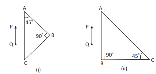
[Figure: Two right-angled isosceles prisms with angles 45°, 45°, 90° and an upright arrow object PQ placed in front of them in two orientations labeled (i) and (ii)]
Answer:
1. In case (i), the rays from object PQ fall normally on the face AC, entering without deviation, and strike the hypotenuse AB at an angle of incidence equal to 45°, which is greater than the critical angle 41°.
2. Total internal reflection takes place at the hypotenuse AB, and the rays emerge from the base BC, forming an inverted image.
3. In case (ii), rays strike the face AB or BC such that total internal reflection occurs, or they pass through depending on normal incidence, rotating the image orientation accordingly.
4. Ray tracing confirms total internal reflection occurs because the angle of incidence (45°) exceeds the critical angle (41°).
Teacher's Note:
a) Total internal reflection occurs when the angle of incidence exceeds the critical angle.
b) Students often draw normal incidence incorrectly without showing the perpendicular entry.
c) Use arrows on the ray paths to clearly indicate the direction of light propagation.
17. (a) Draw a labelled ray diagram to show the formation of an image by a compound microscope. Write the expression for its magnifying power. [3 Marks]
Answer:
1. The ray diagram consists of two converging lenses: a small aperture objective lens and a large aperture eyepiece lens aligned coaxially.
2. The object is placed just beyond the focal length of the objective, forming a real, inverted, and magnified intermediate image near the focal point of the eyepiece.
3. The eyepiece acts as a simple magnifier to produce a final virtual, magnified, and inverted image at the least distance of distinct vision.
4. Magnifying power expression: m = \(-\frac{v_o}{u_o}\)(\(1 + \frac{D}{f_e}\)) or approximately \(-\frac{L}{f_o}\)(\(1 + \frac{D}{f_e}\)).
Teacher's Note:
a) Clearly label the objective lens, eyepiece, focal lengths, and object and image distances.
b) Ensure arrows on the light rays indicate proper propagation directions.
c) Mention the tube length L as the distance between the focal points of objective and eyepiece.
18. (b) Define resolving power of a compound microscope. How does the resolving power of a compound microscope change, when (i) refractive index of the medium between the object and the objective lens increases and (ii) Wavelength of the radiation used is increased? [3 Marks]
Answer:
1. Resolving power of a compound microscope is defined as the inverse of the minimum separation distance between two point objects that can be resolved distinctly by the microscope, given by R.P. = \(\frac{2n \sin\theta}{\lambda}\).
2. (i) When the refractive index (n) of the medium between the object and objective lens increases, the resolving power increases proportionally.
3. (ii) When the wavelength (\(\lambda\)) of the radiation used is increased, the resolving power decreases because it is inversely proportional to the wavelength.
Teacher's Note:
a) Memorize Abbe's limit of resolution formula to easily derive dependencies.
b) A common mistake is confusing resolving limit with resolving power.
c) Immersion oil is often used to increase the refractive index and hence improve resolution.
19. Define the term wave front? Using Huygen's construction draw a figure showing the propagation of a plane wave reflecting at the interface of the two media. Show that the angle of incidence is equal to the angle of reflection. [3 Marks]
Answer:
1. A wave front is defined as the continuous locus of all adjacent points of a medium vibrating in the same phase.
2. Using Huygen's construction, draw incident plane wavefront AB striking a reflecting surface XY at an angle of incidence i.
3. Construct secondary wavelets from the surface to form the reflected wavefront A'B' making an angle of reflection r.
4. From the congruence of triangles involved in the wave propagation construction, prove that angle i equals angle r.
Teacher's Note:
a) Every point on a wavefront acts as a secondary source of light emitting wavelets.
b) Draw clear normal lines to represent rays corresponding to the wavefronts.
c) Triangle congruence (\(\triangle ABC \cong \triangle A'B'C\)) is the core geometric proof.
20. Define the term 'wave front'. Draw the wave front and corresponding rays in the case of a (i) diverging spherical wave (ii) plane wave. Using Huygen's construction of a wave front, explain the refraction of a plane wave front at a plane surface and hence deduce Snell's law. [3 Marks]
Answer:
1. A wave front is the locus of all points in a medium having the same phase of vibration.
2. (i) For a diverging spherical wave, wavefronts are expanding concentric spheres with outward pointing radial rays; (ii) For a plane wave, wavefronts are parallel planes with parallel perpendicular rays.
3. Using Huygen's construction for refraction, let a plane wave front AB incident on a boundary separating two media with speeds \(v_1\) and \(v_2\) refract to form A'B'.
4. From the geometry of secondary wavelets, \(\sin i = \frac{v_1 t}{BC}\) and \(\sin r = \frac{v_2 t}{BC}\), giving \(\frac{\sin i}{\sin r}\) = \(\frac{v_1}{v_2}\) = \(\frac{n_2}{n_1}\), which is Snell's law.
Teacher's Note:
a) Wavefronts are always perpendicular to their corresponding rays of light.
b) Keep track of speeds in different media (\(v_1 = c/n_1\) and \(v_2 = c/n_2\)).
c) Snell's law derivation using wave theory is a classic repeating board examination question.
21. What is meant by interference of light? Write any two conditions necessary for obtaining well-defined and sustained interference pattern of light. [2 Marks]
Answer:
1. Interference of light is the phenomenon of redistribution of light energy in the region of superposition of two or more light waves from coherent sources.
2. Conditions for sustained interference: (i) The two sources must be coherent, maintaining a constant phase difference. (ii) The sources must be monochromatic, emitting light of a single wavelength.
Teacher's Note:
a) The principle of superposition forms the underlying concept of interference.
b) Ensure both coherence and monochromatic nature are clearly stated for full credit.
22. What is the effect on the interference fringes in a Young's double slit experiment due to each of the following operations? Give reason for your answer: (i) Separation between two slits is increased & (ii) monochromatic source is replaced by a source of white light. [2 Marks]
Answer:
1. (i) Fringe width decreases because fringe width \(\beta = \frac{\lambda D}{d}\), which is inversely proportional to the slit separation d.
2. (ii) A continuous white central fringe is formed, flanked by coloured fringes because different wavelengths produce fringes of different widths.
Teacher's Note:
a) Use the fringe width formula to justify inverse and direct proportionalities.
b) Remember that violet fringes are closest to the central white fringe and red fringes are farthest.
23. Draw the curve depicting variation of intensity in the interference pattern in Young's double slit experiment. State conditions for obtaining sustained interference pattern of light. [3 Marks]
Answer:
1. The intensity curve shows uniform alternating maxima and minima where all bright fringes have equal maximum intensity.
2. Condition 1: The sources must be coherent so that phase difference remains constant with time.
3. Condition 2: The emitting sources should be very close to each other and narrow to prevent overlapping of diffraction effects.
Teacher's Note:
a) Sketch equal intensity peaks spaced evenly across the interference pattern.
b) Highlight the distinction between interference intensity distribution and single-slit diffraction.
c) Mentioning phase constancy is crucial for the definition of sustained interference.
24. In a single slit diffraction pattern, how is angular width of central bright maximum changed when (i) the slit width is decreased, (ii) the distance between the slit and the screen is increased, & (iii) light of smaller wavelength is used? Justify your answers. [3 Marks]
Answer:
1. (i) Angular width increases because angular width is given by \(\frac{2\lambda}{a}\), which is inversely proportional to slit width a.
2. (ii) Angular width remains unchanged because it is independent of the distance D between the slit and the screen.
3. (iii) Angular width decreases because angular width is directly proportional to the wavelength \(\lambda\).
Teacher's Note:
a) Formula used is angular width \(\theta = \frac{2\lambda}{a}\).
b) Students often confuse linear width with angular width when distance D changes.
c) Check that wavelength proportionality is clearly linked to the numerator of the expression.
25. Why is diffraction of sound waves easier to observe than diffraction of light waves? What two main changes in diffraction pattern of a single slit will you observe when the monochromatic source of light is replaced by a source of white light? [3 Marks]
Answer:
1. Diffraction requires an obstacle size comparable to the wavelength of the wave. Sound waves have much larger wavelengths (centimetres to metres) comparable to everyday objects, whereas light waves have very small wavelengths (\(10^{-7}\) m).
2. Change 1: The central maximum will be white at the centre with coloured fringes on either side.
3. Change 2: The diffraction bands will be coloured because different component wavelengths have different fringe widths.
Teacher's Note:
a) Relate wavelength magnitude directly to the size of common obstacles.
b) Note that white light produces overlapping diffraction patterns for different colours.
c) Emphasize that the central maximum remains white due to superposition of all colours at zero path difference.
26. In a single slit diffraction experiment, if the width of the slit is doubled, how does the (i) intensity of light and (ii) width of the central maximum change? Give reason for your answer. [2 Marks]
Answer:
1. (i) Intensity increases because doubling the slit width quadruples the area and amount of light entering the slit, concentrating the intensity.
2. (ii) Width of the central maximum is halved because angular width is inversely proportional to the slit width a.
Teacher's Note:
a) Intensity is proportional to the square of the amplitude or slit width.
b) Keep the inverse relation \(\theta \propto \frac{1}{a}\) in mind for central maximum width.
27. What is wave front? What is the geometrical shape of a wave front emerging from a convex lens when point source is placed at the focus? [2 Marks]
Answer:
1. A wave front is the continuous locus of all adjacent points vibrating in the same phase.
2. The geometrical shape of the emerging wave front is a plane wave front.
Teacher's Note:
a) A spherical wave front diverging from the focus becomes planar after refraction through a convex lens.
b) Rays emerging parallel correspond to a plane wave front.
28. What is wave front? Distinguish between a plane wave front and a spherical wave front. Explain with the help of a diagram, the refraction of a plane wave front at a plane surface using Huygens's construction. [4 Marks]
Answer:
1. A wave front is the locus of all points in a medium having the same phase of oscillation.
2. Plane wave front originates from a distant source (like a star) where rays are parallel, while a spherical wave front originates from a point source.
3. Refraction using Huygens construction shows that incident and refracted wave fronts obey Snell's law, with speed changing across the boundary.
4. \(\frac{\sin i}{\sin r} = \frac{v_1}{v_2} = \frac{n_2}{n_1}\).
[Figure: Diagram showing refraction of a plane wave front AB incident on a refracting surface separating two media with speeds v1 and v2, forming refracted wave front CD]
Teacher's Note:
a) State the definition of wave front clearly before giving distinctions.
b) Draw clear ray normals and secondary wavelets in the Huygens construction diagram.
c) Derive Snell's law geometrically using similar triangles in the construction.
d) Verify that frequency remains constant while wavelength changes across the medium boundary.
29. Using Huygens's principle show that for parallel beam incident on a reflecting surface the angle of reflection is equal to the angle of incidence. [3 Marks]
Answer:
1. Let a plane wave front AB be incident at an angle i on a reflecting surface MM'.
2. Using Huygens's principle, secondary wavelets from point B travel a distance vt to reach point C in time t, constructing the reflected wave front CD.
3. In triangles ABC and ADC, angle ABC equals angle ADC equals 90°, side AC is common, and side AB equals CD (vt), making the triangles congruent, hence angle i equals angle r.
[Figure: Diagram showing reflection of a plane wave front AB at a reflecting surface to form reflected wave front CD with angles of incidence i and reflection r]
Teacher's Note:
a) Apply Huygens principle by constructing secondary wavelets from the reflecting boundary.
b) Use triangle congruence to prove the laws of reflection cleanly.
c) Ensure angle markings for i and r are geometrically accurate in the diagram.
30. Distinguish between unpolarised and plane polarised light. An unpolarised light is incident on the boundary between two transparent media. State the condition when the reflected wave is totally plane polarised. Find out the expression for the angle of incidence in this case. [4 Marks]
Answer:
1. Unpolarised light has electric field vibrations in all directions perpendicular to the direction of propagation, whereas plane polarised light has vibrations confined to a single plane.
2. The reflected wave is totally plane polarised when unpolarised light is incident at Brewster's angle (polarising angle), where the reflected and refracted rays are mutually perpendicular.
3. Applying Snell's law at angle of incidence i equal to polarising angle \(i_p\): \(n = \frac{\sin i_p}{\sin r}\).
4. Since \(r = 90^\circ - i_p\), we get \(\tan i_p = n\), which is Brewster's law.
Teacher's Note:
a) Emphasize the directional restriction of electric field vectors in polarisation.
b) State Brewster's condition clearly: angle between reflected and refracted ray is 90°.
c) Show the complete derivation leading from Snell's law to \(\tan i_p = n\).
d) Verify that refractive index is dimensionless and equals the tangent of the polarising angle.
31. The following data was recorded for values of object distance and the corresponding values of image distance in the experiment on study of real image formation by a convex lens of power +5D. One of the observations is incorrect. Identify the observation and give reason for your choice. [3 Marks]
| S.No. | 1 | 2 | 3 | 4 | 5 | 6 |
|---|---|---|---|---|---|---|
| Object distance (cm) | 25 | 30 | 35 | 45 | 50 | 55 |
| Image distance (cm) | 97 | 6 | 37 | 35 | 32 | 30 |
Answer:
1. Focal length of the lens \(f = \frac{1}{P} = \frac{1}{+5}\) m = +0.2 m = +20 cm.
2. Using lens formula \(\frac{1}{f} = \frac{1}{v} - \frac{1}{u}\), for observation 2 with \(u = -30\) cm, we calculate image distance v: \(\frac{1}{20} = \frac{1}{v} - \frac{1}{-30} \implies \frac{1}{v} = \frac{1}{20} - \frac{1}{30} = \frac{1}{60}\), giving \(v = +60\) cm.
3. The recorded image distance for observation 2 is 6 cm, which is incorrect and should be 60 cm.
Teacher's Note:
a) Calculate the focal length first using power P = 1/f.
b) Verify each data point using the lens equation with proper sign conventions.
c) Observation 2 has a gross arithmetic error in the table where image distance is listed as 6 cm instead of 60 cm.
5 MARKS
32. (i) Derive the mirror formula which gives the relation between f, v and u. What is the corresponding formula for a thin lens?
(ii) Calculate the distance d, so that a real image of an object at O, 15cm in front of a convex lens of focal length 10cm be formed at the same point O. The radius of curvature of the mirror is 20cm. Will the image be inverted or erect? [5 Marks]
Answer:
1. Mirror Formula derivation: Consider a concave mirror forming a real image of an object placed beyond its center of curvature. Using similar triangles between object-mirror-focus geometry, \(\frac{1}{f} = \frac{1}{v} + \frac{1}{u}\).
2. Corresponding formula for a thin lens is \(\frac{1}{f} = \frac{1}{v} - \frac{1}{u}\).
3. For the lens, object distance u = -15 cm and focal length f = 10 cm. Using the lens formula: \(\frac{1}{v} - \frac{1}{-15} = \frac{1}{10} \implies \frac{1}{v} + \frac{1}{15} = \frac{1}{10} \implies \frac{1}{v} = \frac{1}{10} - \frac{1}{15} = \frac{1}{30}\), so v = +30 cm.
4. For the rays to retrace their path and form the image back at O, the rays must fall normally on the convex mirror. This means the rays must appear to converge at the center of curvature C of the mirror.
5. Therefore, the distance between the lens and mirror is d = v - R = 30 - 20 = 10 cm, and since the rays retrace, the final image formed at O is inverted.
Teacher's Note:
a) The mirror formula relates focal length, image distance, and object distance using similar triangle properties.
b) A common error is mixing up the positive and negative signs for lens and mirror formulas during substitution.
c) Retracing of light rays happens when rays strike a reflecting surface normally along its radius of curvature.
d) Verification shows that object distance for the mirror equals its radius of curvature, satisfying normal incidence.
33. A spherical surface of radius of curvature 'R' separates a rarer and a denser medium as shown in the figure.
Complete the path of the incident ray of light, showing the formation of real image. Hence derive the relation connecting object distance 'u', Image distance 'v' radius of curvature 'R' and the refractive indices 'n1' & 'n2' of the media. Briefly explain how the focal length of a convex lens changes with Increase in wavelength of incident light. [5 Marks]
Answer:
1. Ray diagram completion: An incident ray starts from object O in rarer medium (refractive index n1), strikes the spherical surface at point A, bends towards the normal and forms a real image I in the denser medium (refractive index n2).
2. Derivation: From Snell's law for small angles, n1 i = n2 r, where i and r are angle of incidence and angle of refraction respectively.
3. Using exterior angle property in triangles of the ray geometry with angles corresponding to object, image, and center of curvature: \(i = \alpha + \gamma\) and \(r = \gamma - \beta\).
4. Substituting these into Snell's law and applying small angle approximations for arc and distances, we get the refraction formula: \(\frac{n_2}{v} - \frac{n_1}{u} = \frac{n_2 - n_1}{R}\).
5. Wavelength dependence: According to Cauchy's relation, refractive index decreases with an increase in wavelength (\(n = A + \frac{B}{\lambda^2}\)). From Lens Maker's formula (\(\frac{1}{f} = (n - 1)(\frac{1}{R_1} - \frac{1}{R_2})\)), as wavelength increases, n decreases, which causes the focal length f of a convex lens to increase.
Teacher's Note:
a) This refraction at a spherical surface derivation is a fundamental building block for deriving the lens maker formula.
b) Students often confuse the placement of refractive indices n1 and n2 on the object and image side terms.
c) Mentioning Cauchy's dispersion formula clearly links refractive index variation directly with the incident wavelength.
d) Verification of signs follows standard Cartesian sign conventions where distances measured against incident light are negative.
34. State the assumptions and sign conventions in deriving the Lens maker's formula and also derive an expression for it. [5 Marks]
Answer:
1. Assumptions: The lens is thin, the aperture is small, incident rays make small angles with the principal axis, and the object is a point object placed on the principal axis.
2. Sign conventions: All distances are measured from the optical center of the lens. Distances measured in the direction of incident light are taken as positive, and those measured against the direction of incident light are taken as negative.
3. First surface refraction: Considering refraction at the first spherical surface of refractive index n2 separated by medium n1, the image formed is virtual, given by \(\frac{n_2}{v_1} - \frac{n_1}{u} = \frac{n_2 - n_1}{R_1}\).
4. Second surface refraction: This virtual image acts as a real object for the second surface, yielding \(\frac{n_1}{v} - \frac{n_2}{v_1} = \frac{n_1 - n_2}{R_2}\).
5. Adding both equations and rearranging for object at infinity (u = -infinity, v = f) gives the Lens Maker's formula: \(\frac{1}{f} = (\frac{n_2}{n_1} - 1)(\frac{1}{R_1} - \frac{1}{R_2})\).
Teacher's Note:
a) State all basic geometrical and optical assumptions clearly before jumping into the refraction steps.
b) Do not miss defining relative refractive index terms clearly if the surrounding medium is not air.
c) Combining the two spherical surface refractions step-by-step is crucial for full board credit.
d) Checking boundary conditions like flat surfaces (R equals infinity) confirms the formula correctness.
35. Derive an expression for thin lens formula. [5 Marks]
Answer:
1. Consider a thin convex lens of focal length f placed in a medium of uniform refractive index. Let an object O be placed at a distance u in front of the lens.
2. A ray starting from O is refracted by the first surface and would form an image at a distance v1 if the second surface were absent.
3. Using refraction formula for the first spherical surface: \(\frac{n_2}{v_1} - \frac{n_1}{u} = \frac{n_2 - n_1}{R_1}\).
4. The second surface refracts this ray further to form the final real image at distance v, satisfying: \(\frac{n_1}{v} - \frac{n_2}{v_1} = \frac{n_1 - n_2}{R_2}\).
5. Adding both equations and using Lens Maker's formula equates to the thin lens formula: \(\frac{1}{f} = \frac{1}{v} - \frac{1}{u}\).
Teacher's Note:
a) The thin lens formula directly connects focal length, image distance, and object distance for lenses.
b) Ensure proper substitution of sign conventions for concave and convex lens configurations.
c) This derivation directly utilizes the intermediate image concept established in the lens maker formula.
d) Verification with specific numerical values confirms the validity of the derived algebraic relation.
36. (a) In Young's double slit experiment, deduce the conditions for: (i) constructive and (ii) destructive interference at a point on the screen. Draw a graph showing variation of the resultant intensity in the interference pattern against position 'x' on the screen.
(b) Compare and contrast the pattern which is seen with two coherently illuminated narrow slits in Young's experiment with that seen for a coherently illuminated single slit producing diffraction. [5 Marks]
Answer:
1. Let two coherent waves from slits \(S_1\) and \(S_2\) have displacements given by \(y_1 = a \cos(\omega t)\) and \(y_2 = a \cos(\omega t + \phi)\).
2. By superposition principle, the resultant displacement is \(y = y_1 + y_2\), and the resultant intensity is proportional to the square of the amplitude, \(I = 4I_0 \cos^2\left(\frac{\phi}{2}\right)\), where \(I_0 = a^2\).
3. (i) Constructive interference occurs when phase difference \(\phi = 2n\pi\) (where \(n = 0, 1, 2, \dots\)) and path difference \(\Delta x = n\lambda\), resulting in maximum intensity \(I_{max} = 4I_0\).
4. (ii) Destructive interference occurs when phase difference \(\phi = (2n + 1)\pi\) and path difference \(\Delta x = (2n + 1)\frac{\lambda}{2}\), resulting in minimum intensity \(I_{min} = 0\).
5. (b) Comparison: Interference fringes are of equal width, all maxima have the same high intensity, and minima are completely dark; diffraction fringes have a central maximum which is twice as wide and much brighter, with secondary maxima of decreasing intensity.
Teacher's Note:
a) The condition for interference depends entirely on the constant phase difference and path difference between two individual wavefronts.
b) Students often confuse equal width interference fringes with the diminishing secondary maxima of single slit diffraction.
c) Mentioning the mathematical expression for intensity \(I = 4I_0 \cos^2(\phi/2)\) helps secure full credit in the derivation part.
d) The graph must clearly show equidistant peaks of uniform height for the interference pattern.
37. State Huygens principle. Using the geometrical construction of secondary wavelets, explain the refraction of a plane wave front incident at a plane surface. Hence verify Snell's law of refraction. Illustrate with the help of diagrams the action of: (i) convex lens and (ii) concave mirror on a plane wave front incident on it. [5 Marks]
Answer:
1. Huygens Principle: Every point on a given wavefront acts as a source of secondary spherical disturbance, emitting secondary wavelets, and the new position of the wavefront at any later time is the envelope of these secondary wavelets.
2. Refraction Verification: Let a plane wavefront AB be incident on a refracting surface XY separating two media with refractive indices \(n_1\) and \(n_2\) and speeds \(v_1\) and \(v_2\).
3. Time taken for light to travel from B to B' is \(t = \frac{BB'}{v_1} = \frac{AC \sin i}{v_1}\), and the secondary wavelet from A travels a distance \(AC = v_2 t\), so \(t = \frac{AC \sin r}{v_2}\).
4. Equating time gives \(\frac{\sin i}{v_1} = \frac{\sin r}{v_2}\), which yields \(\frac{\sin i}{\sin r} = \frac{v_1}{v_2} = \frac{n_2}{n_1} = \mu\), verifying Snell's law.
5. (i) Convex lens converges a plane wavefront into a spherical converging wavefront; (ii) Concave mirror reflects a plane wavefront into a spherical converging wavefront towards its focus.
Teacher's Note:
a) Huygens principle forms the fundamental geometrical basis for deriving laws of reflection and refraction wave theory.
b) A common error is mixing up the sine ratios for angles of incidence and refraction during wavefront construction.
c) Drawing clear ray diagrams for both the convex lens and concave mirror transforming plane waves is mandatory for full marks.
d) The derivation explicitly connects corpuscular speed ratios to absolute refractive indices of the optical media.
38. What is interference of light? Write two essential conditions for sustained interference pattern to be produced on the screen. Draw a graph showing the variation of intensity versus the position on the screen in Young's experiment when (a) both the slits are opened and (b) one of the slit is closed. What is the effect on the interference pattern in Young's double slit experiment when: (i) Screen is moved closer to the plane of slits? (ii) Separation between two slits is increased. Explain your answer in each case. [5 Marks]
Answer:
1. Interference of light is the phenomenon of redistribution of light energy in the region of superposition of two or more light waves from coherent sources.
2. Essential conditions: The two sources must be coherent (constant phase difference) and monochromatic (same single wavelength).
3. Intensity graphs: (a) When both slits are opened, periodic alternate maxima and minima of high contrast are observed; (b) When one slit is closed, the interference pattern disappears, leaving a broad single-slit diffraction pattern with a central maximum.
4. (i) When screen is moved closer to the slits (decreasing D), fringe width \(\beta = \frac{\lambda D}{d}\) decreases, so fringes crowd closer together.
5. (ii) When separation between slits (d) is increased, fringe width \(\beta\) decreases proportionally, making the fringes narrower and closer.
Teacher's Note:
a) Sustained interference requires permanent phase relationships, which independent lamps can never provide.
b) Students must remember that closing one slit turns the setup into a single-slit diffraction experiment.
c) Fringe width formula \(\beta = \lambda D / d\) should be explicitly quoted for analyzing parameter changes.
d) Graphical representations must clearly distinguish between double-slit uniform maxima and single-slit central diffraction broadening.
39. What are coherent sources of light? Two slits in Young's double slit experiment are illuminated by two different sodium lamps emitting light of the same wavelength. Why is no interference pattern observed?
(b) Obtain the condition for getting dark and bright fringes in Young's experiment. Hence write the expression for the fringe width.
(c) If S is the size of the source and its distance from the plane of the two slits, what should be the criterion for the interference fringes to be seen? [5 Marks]
Answer:
1. Coherent sources are sources of light that emit light waves of the same frequency, wavelength, and constant initial phase difference.
2. No interference is observed with two independent sodium lamps because independent sources cannot maintain a constant phase difference over time, leading to rapid random phase changes.
3. (b) Condition for bright fringes (constructive interference): path difference \(\Delta x = n\lambda\); condition for dark fringes (destructive interference): path difference \(\Delta x = (2n + 1)\frac{\lambda}{2}\); Fringe width expression is \(\beta = \frac{\lambda D}{d}\).
4. (c) The criterion for fringes to be clearly seen is that the source condition \(\frac{S}{s} \lt \frac{\lambda}{d}\) must be satisfied, meaning the source size must be sufficiently small compared to the slit separation.
Teacher's Note:
a) Two independent sources of identical wavelength fail to interfere because atomic emissions are random and incoherent.
b) Always write the path difference conditions in terms of integer multiples for bright and half-integer multiples for dark fringes.
c) The spatial coherence condition links source size, distance, and slit separation for visibility.
d) High contrast fringes require proper balancing of source dimensions to avoid overlapping diffraction envelopes.
40. What do we understand by 'polarization of wave'? How does this phenomenon help us to decide whether a given wave is transverse or longitudinal in nature? [3 Marks]
Answer:
1. Polarization of a wave is the restriction of the vibrations of a wave to a single plane perpendicular to the direction of propagation.
2. This phenomenon is exclusive to transverse waves; longitudinal waves (like sound waves) oscillate parallel to the direction of propagation and cannot be polarized.
3. If an incoming wave shows variation in intensity when passed through a rotating polarizer (analyzer), it proves definitively that the wave is transverse in nature.
Teacher's Note:
a) Polarization confirms the vector transverse nature of electromagnetic waves.
b) Do not confuse longitudinal pressure waves with transverse field vector oscillations.
c) Mentioning Malus law adds conceptual depth when discussing intensity variations during polarization tests.
41. Light from an ordinary source (say, a sodium lamp) is passed through a Polaroid sheet P1. The transmitted light is then made to pass through a second Polaroid sheet P2 which can be rotated so that the angle \(\theta\) between the two Polaroid sheets varies from \(0^\circ\) to \(90^\circ\). Show graphically the variation of intensity of light, transmitted by P1 and P2 as a function of the angle \(\theta\). Take the incident beam intensity as I0. Why does the light from a clear blue portion of the sky, show a rise and fall of intensity when viewed through a Polaroid which is rotated? [5 Marks]
Answer:
1. Unpolarized light passing through Polaroid P1 becomes polarized with intensity \(I_1 = \frac{I_0}{2}\).
2. When this polarized light passes through Polaroid P2 at angle \(\theta\), the transmitted intensity varies according to Malus law: \(I = I_1 \cos^2\theta = \left(\frac{I_0}{2}\right)\cos^2\theta\).
3. At \(\theta = 0^\circ\), intensity is maximum (\(\frac{I_0}{2}\)); at \(\theta = 90^\circ\), intensity becomes zero (minimum).
4. Light from a clear blue sky shows a rise and fall of intensity upon rotating a Polaroid because sunlight gets linearly polarized by scattering off air molecules in the atmosphere.
Teacher's Note:
a) Malus law (\(I = I_0 \cos^2\theta\)) is the core governing formula for transmission through crossed polarizers.
b) Students often forget that unpolarized light passing through the first polarizer drops in intensity by half.
c) Rayleigh scattering explains why sky light is polarized perpendicular to the direction of incident sunlight.
d) The graph must show a smooth cosine-squared decay curve starting from maximum intensity down to zero.
42. (a) Draw a ray diagram to show the refraction of light through a glass prism. Hence obtain the relation for the angle of deviation in terms of the angle of incidence, angle of emergence and the angle of the prism.
(b) Deduce the expression for refractive index of glass prism in term of angle of prism and angle of minimum deviation. [5 Marks]
Answer:
1. Ray Diagram: A ray of light PQ is incident on the refracting face AB of a prism at angle i, undergoes refraction at angle r1, travels inside the prism as QR, strikes face AC at angle r2, and emerges out along RE making an angle of emergence e.
2. Relation for angle of deviation: In △MQR formed by the intersection of the two refracted rays, the exterior angle is equal to the sum of interior opposite angles, so the deviation at first surface is (i - r1) and at second surface is (e - r2).
3. Total angle of deviation \(\delta\) = (i - r1) + (e - r2) = (i + e) - (r1 + r2).
4. From geometry of the prism, r1 + r2 = A, where A is the angle of the prism.
5. Substituting this gives the deviation relation: \(\delta\) = i + e - A.
6. Refractive index expression: At minimum deviation, \(\delta = \delta_m\), i = e, and r1 = r2 = r, which implies 2r = A or r = A / 2.
7. Substituting these into Snell's law at the first face: n = \(\frac{\sin i}{\sin r_1}\) = \(\frac{\sin\left(\frac{A + \delta_m}{2}\right)}{\sin\left(\frac{A}{2}\right)}\).
Teacher's Note:
a) The prism formula relates refractive index, angle of prism, and angle of minimum deviation directly.
b) Students often confuse angle of deviation with angle of deviation at a single surface.
c) Snell's law must be correctly applied at the point of incidence using proper normal conventions.
d) At minimum deviation, the light ray passes symmetrically through the equilateral or given prism.
Free study material for Physics
Free CBSE Study Guides: Class 12 Physics Chapter 09 Ray Optics and Optical Instruments
Quick Revision Material for Chapter 09 Ray Optics and Optical Instruments
Review targeted study resources for Chapter 09 Ray Optics and Optical Instruments tailored for Class 12 learners. Utilizing these structured notes and quick-revision tools ensures complete alignment with current CBSE evaluation standards.
Expert Notes and Solved Exam Questions
Designed around the official curriculum, these study guides guarantee standard compliance. Reviewing step-by-step solutions clarifies complex sub-topics within Chapter 09 Ray Optics and Optical Instruments and demystifies standard marking schemes for Physics evaluations.
Additional Study Resources for Class 12
For peak performance in upcoming evaluations, integrate official Physics sample papers directly into your study schedule. Follow up your revision by attempting online MCQ tests for Chapter 09 Ray Optics and Optical Instruments to refine calculation speed and precision.
FAQs
Our advanced study package for Chapter 09 Ray Optics and Optical Instruments includes detailed concepts, diagrams, Mind Maps, and explanation of complex topics to ensure Class 12 students learn as per syllabus for 2026 exams.
The Mind Maps provided for Chapter 09 Ray Optics and Optical Instruments act as visual anchors which will help faster recall during high-pressure exams.
Yes, teachers use our Class 12 Physics resources for lesson planning as they are in simple language and have lot of solved examples.
Yes, You can download the complete, mobile-friendly PDF of the Physics Chapter 09 Ray Optics and Optical Instruments advanced resources for free.
Yes, our subject matter experts have updated the Chapter 09 Ray Optics and Optical Instruments material to align with the rationalized NCERT textbooks and have removed deleted topics and added new competency-based questions.