

Advanced Study Material for Class 12 Physics: Chapter 01 Electric Charges and Fields
Access comprehensive study materials and useful resources for Chapter 01 Electric Charges and Fields using the CBSE Class 12 Physics Magnetic Effects of Electric Current Solved Examples. Designed to align with the 2026-27 CBSE academic guidelines, these advanced resources help Class 12 Physics students reinforce core concepts beyond standard textbooks.
Practice Class 12 Physics Resources: Chapter 01 Electric Charges and Fields
Access the complete useful resource PDF for Class 12 Physics below. Regular practice with these targeted academic notes builds familiarity with complex topics and helps secure higher marks in final school evaluations.
CBSE Class 12 Physics Magnetic Effects of Electric Current Solved Examples. Please refer to the examination notes which you can use for preparing and revising for exams. These notes will help you to revise the concepts quickly and get good marks.
SOLVED EXAMPLES
CLASS XII : PHYSICS
MAGNETIC EFFECTS OF ELECTRIC CURRENT
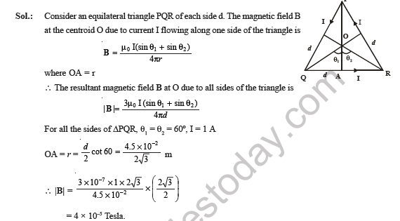
Ex.1 A current of one ampere is flowing along the sides of an equilateral triangle of side 4.5 × 10⁻² m. Find the magnetic field at the centroid of the triangle.
Answer:
1. Let the side be d and the centroid O. The distance from O to each side is r = OA = \( \frac{d}{2} \cot 60° \) = \( \frac{d}{2\sqrt{3}} \).
2. Field at O due to one side: B = \( \frac{\mu_0 I (\sin\theta_1 + \sin\theta_2)}{4\pi r} \), where θ₁ = θ₂ = 60° for each side.
3. For one side, sin60° + sin60° = √3, so Bside = \( \frac{\mu_0 I \sqrt{3}}{4\pi r} \).
4. All three sides give fields in the same direction, so B = 3 × Bside = \( \frac{3\sqrt{3}\,\mu_0 I}{4\pi r} \) with r = \( \frac{d}{2\sqrt{3}} \).
5. B = \( \frac{18\,\mu_0 I}{4\pi d} \) = \( \frac{9\,\mu_0 I}{2\pi d} \) = \( \frac{9 \times 2 \times 10^{-7} \times 1}{4.5 \times 10^{-2}} \) T.
6. Hence, B = 4 × 10⁻⁵ T, perpendicular to the plane of the triangle.
Teacher's Note:
a) The distance from the centroid to a side is the perpendicular distance, which is d divided by 2√3.
b) Three equal fields add up because each side pushes the field in the same direction at O.
c) Use μ₀/4π = 10⁻⁷ T m/A to keep the arithmetic short.
Ex.2 The centres of two similar coils P and Q having same number of turns are located at coordinates (0.4, 0) m and (0, 0.3) m such that the plane of coils are perpendicular to X and Y axes respectively. The areas of cross sections of coils P and Q are in the ratio 4 : 3. The coil P has 16 A current in clockwise direction and the coil Q has 9√3 A current in anticlockwise direction as seen from the origin. A small compass needle is placed at the origin. Find the deflection of the needle assuming the earth's magnetic field negligible and the radii of the coils very small as compared to their distances from the origin. (Take radius of ring is small)
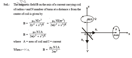

[Figure: Coil P is centred at (0.4, 0) m on the X-axis with its plane perpendicular to the X-axis. Coil Q is centred at (0, 0.3) m on the Y-axis with its plane perpendicular to the Y-axis. A compass needle at the origin O makes an angle θ with the X-axis. Field arrows BP along the X-axis and BQ along the negative Y direction are drawn at O.]
Answer:
1. Field on the axis of a coil far away (r ≪ x): B = \( \frac{\mu_0 N I A}{2\pi x^3} \).
2. Field at O due to coil P (distance x = 0.4 m): BP = \( \frac{\mu_0 N I_P A_P}{2\pi (0.4)^3} \), along the X-axis.
3. Field at O due to coil Q (distance y = 0.3 m): BQ = \( \frac{\mu_0 N I_Q A_Q}{2\pi (0.3)^3} \), along the Y-axis.
4. The needle lies along the net field, so tanθ = \( \frac{B_Q}{B_P} \) = \( \frac{I_Q}{I_P} \times \frac{A_Q}{A_P} \times \frac{x^3}{y^3} \).
5. tanθ = \( \frac{9\sqrt{3}}{16} \times \frac{3}{4} \times \left( \frac{0.4}{0.3} \right)^3 \) = \( \sqrt{3} \).
6. Hence, θ = 60°, so the needle deflects by 60° from the X-axis.
Teacher's Note:
a) Both coils have the same number of turns, so N cancels in the ratio.
b) The area ratio is 4 : 3 for P and Q, so AQ/AP = 3/4 in the working.
c) The needle follows the resultant of the two fields, and the directions of the currents only change the sign of the angle.
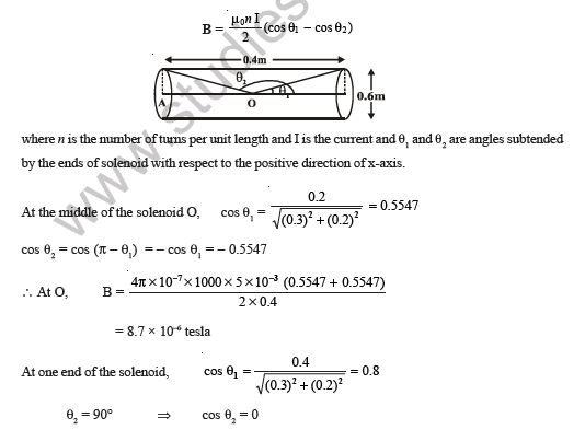
Ex.3. A solenoid of length 0.4 m and diameter 0.6 m consists of a single layer of 1000 turns of fine wire carrying a current of 5.0 milliampere. Find the magnetic field on the axis at the middle and at the ends of a solenoid.
Answer:
1. Field at a point on the axis: B = \( \frac{\mu_0 N I}{2L} \) (cos θ₁ - cos θ₂), where N = 1000 turns, L = 0.4 m, I = 5.0 × 10⁻³ A.
2. At the middle O, the half length is 0.2 m and the radius is 0.3 m, so cos θ₁ = \( \frac{0.2}{\sqrt{(0.3)^2 + (0.2)^2}} \) = 0.5547, and cos θ₂ = -0.5547.
3. BO = \( \frac{4\pi \times 10^{-7} \times 1000 \times 5.0 \times 10^{-3}}{2 \times 0.4} \) × (0.5547 + 0.5547) = 8.7 × 10⁻⁶ T.
4. At one end A, cos θ₁ = \( \frac{0.4}{\sqrt{(0.3)^2 + (0.4)^2}} \) = 0.8, and θ₂ = 90°, so cos θ₂ = 0.
5. BA = \( \frac{4\pi \times 10^{-7} \times 1000 \times 5.0 \times 10^{-3}}{2 \times 0.4} \) × 0.8 = 6.28 × 10⁻⁶ T.
6. Hence, the field is 8.7 × 10⁻⁶ T at the middle and 6.28 × 10⁻⁶ T at each end.
Teacher's Note:
a) At the middle, the two angles are equal in size and opposite in sign, so the field is the largest.
b) The end field is about 0.7 times the middle field because one end angle is 90°.
c) Use the length of the solenoid, 0.4 m, as the denominator, not its diameter.
Ex.4. A proton of mass 1.6 × 10⁻²⁷ kg and charge 1.6 × 10⁻¹⁹ C enters a region of uniform magnetic field of strength 1 tesla along the direction shown in the figure such that its speed is 10⁷ m/s.
(i) If the magnetic field is directed along the inward normal to the plane of the paper and the particle leaves the region of the field at the point F, find the distance EF and the angle.
[Figure: A vertical boundary line with points F (upper) and E (lower) marked on it. A region of uniform magnetic field, marked with crosses, lies to the right of the boundary. A particle track enters at E from the lower left, making 45° with the boundary, and leaves at F towards the upper left, with the angle θ marked at F between the boundary and the path.]
Answer:
1. Radius of the path: R = \( \frac{mv}{qB} \) = \( \frac{1.6 \times 10^{-27} \times 10^{7}}{1.6 \times 10^{-19} \times 1} \) = 0.1 m.
2. The particle enters at 45° to the boundary, so the chord on the boundary is EF = 2R sin 45°.
3. EF = 2 × 0.1 × \( \frac{1}{\sqrt{2}} \) = 0.141 m.
4. The particle leaves at the same angle to the boundary as it entered, so θ = 45°.
Teacher's Note:
a) Radius comes from the balance of magnetic force and centripetal force, R = mv/qB.
b) A chord of a circle that meets a line at angle α has length 2R sin α.
c) The entry and exit angles to the boundary are equal, which gives θ directly.
(ii) If the direction of the magnetic field is along the outward normal to the plane of the paper, find the time spent by the particle in the region of magnetic field after entering at E.
[Figure: The same vertical boundary with E and H marked on it and the centre O to the left of the boundary. The arc from E through C to H lies inside the field region, and the point C is marked on the right side with the radius R shown from O.]
Answer:
1. The radius is the same, R = 0.1 m, and the centre O lies on the left of the boundary.
2. The angle ∠EOH = 90°, so the arc of the circle outside the field is 90° and the arc inside the field is 270°.
3. Length of arc ECH = 2πR - \( \frac{\pi R}{2} \) = \( \frac{3\pi R}{2} \).
4. Time spent in the field = \( \frac{\text{arc length}}{v} \) = \( \frac{3\pi R}{2v} \) = \( \frac{3 \times 3.14 \times 0.1}{2 \times 10^{7}} \) s = 4.71 × 10⁻⁸ s.
Teacher's Note:
a) The particle travels the major arc inside the field, so the arc is 270°, not 90°.
b) Time is the arc length divided by speed, and it is independent of the radius through the period.
Ex.5. A beam of protons having a velocity of 4 × 10⁵ metres per second enters a uniform magnetic field of 0.3 tesla at an angle of 60° to the magnetic field. Find the radius of the helical path taken by the proton beam. Find the time period of rotation and pitch of the helix.
Answer:
1. Component parallel to the field: v∥ = v cos 60° = 4 × 10⁵ × \( \frac{1}{2} \) = 2 × 10⁵ m/s.
2. Component perpendicular to the field: v⊥ = v sin 60° = 4 × 10⁵ × \( \frac{\sqrt{3}}{2} \) = 3.464 × 10⁵ m/s.
3. Radius of the helix: R = \( \frac{m v_{\perp}}{qB} \) = \( \frac{1.67 \times 10^{-27} \times 3.464 \times 10^{5}}{1.6 \times 10^{-19} \times 0.3} \) = 1.2 × 10⁻² m = 1.2 cm.
4. Time period: T = \( \frac{2\pi m}{qB} \) = \( \frac{2 \times 3.14 \times 1.67 \times 10^{-27}}{1.6 \times 10^{-19} \times 0.3} \) = 2.185 × 10⁻⁷ s.
5. Pitch of the helix = v∥ × T = 2 × 10⁵ × 2.185 × 10⁻⁷ = 4.37 × 10⁻² m.
Teacher's Note:
a) Only the perpendicular component of velocity produces the circular motion.
b) The time period does not depend on the speed or the angle, only on q, B and m.
c) Pitch is the distance moved along the field in one full turn, so it uses the parallel component.
Ex.6. A wire ABCDEF (with each side of length L) is bent as shown in the figure and is carrying current I in a uniform magnetic induction B parallel to the y-axis. What is force experienced by wire.
[Figure: A wire ABCDEF with each side of length L, bent in three dimensions. The x, y and z axes meet at the origin. Corner points A, B, C, D, E and F are marked. A current arrow I is shown on the segment EF, and the segment DE is drawn dashed.]
Answer:
1. Join A and F with a straight conducting wire. The network ABCDEFA is a closed loop.
2. A closed loop placed in a uniform magnetic field has no net force, so FABCDEF + FAF = 0.
3. The force on a straight wire AF carrying current I is FAF = I (AF vector) × B, and its magnitude is BIL, directed along the negative z-axis.
4. Therefore, FABCDEF = -FAF, which is BIL along the positive z-axis.
Teacher's Note:
a) Closing the wire into a loop is a standard trick, because the net force on a closed loop in a uniform field is zero.
b) The force on a bent wire depends only on its end points, not on the shape between them.
c) Check the direction with the right hand rule for the cross product of the current direction and B.
Ex.7. A charge Q is spread uniformly over an insulated ring of radius R. What is the magnetic moment of the ring if it is rotated with an angular velocity ω with respect to the normal axis.
Answer:
1. Charge on a small element dl of the ring: dq = \( \frac{Q}{2\pi R} \) dl.
2. This element goes round the loop at frequency \( \frac{\omega}{2\pi} \), so the current it carries is dI = \( \frac{Q}{2\pi R} \) dl × \( \frac{\omega}{2\pi} \).
3. Magnetic moment of this element: dM = (dI) × πR² = \( \frac{Q\omega R}{4\pi} \) dl.
4. Integrating around the ring, M = \( \frac{Q\omega R}{4\pi} \) × 2πR = \( \frac{1}{2} \) QωR².
5. Hence, the magnetic moment is \( \frac{1}{2} \) QωR².
Teacher's Note:
a) A rotating charge is equivalent to a current, I = Q × frequency.
b) The result is the same as I × area, using I = Qω/2π and area πR².
c) The magnetic moment grows with the square of the radius, so a larger ring gives a much larger moment.
Ex.8. What is the value of shunt which passes 10% of the main current through a galvanometer of 99 ohm?
Answer:
1. Let the main current be I, so the galvanometer current IG = 10% of I = 0.1 I, and the shunt current = I - 0.1 I = 0.9 I.
2. Potential difference across both branches is equal: (I - IG) S = IG G.
3. S = \( \frac{I_G G}{I - I_G} \) = \( \frac{0.1 I \times 99}{0.9 I} \) = \( \frac{0.1 \times 99}{0.9} \).
4. Hence, S = 11 Ω.
Teacher's Note:
a) A shunt takes most of the current, so its resistance is small compared with the galvanometer.
b) The main current I cancels, so the answer does not depend on the value of I.
c) Check that the shunt current is 90% of the main current.
Ex.9. If a shunt of value \( \frac{1}{n} \) times the galvanometer resistance is applied to a moving coil galvanometer, by what factor will its current sensitivity will change?
Answer:
1. Let θ be the deflection of the galvanometer alone and θ' the deflection with the shunt, for the same main current I. Current sensitivity is CS = \( \frac{\theta}{I} \) and CS' = \( \frac{\theta'}{I} \).
2. Deflection is proportional to the current through the galvanometer, so \( \frac{\theta'}{\theta} \) = \( \frac{I_G}{I} \).
3. With shunt S = \( \frac{G}{n} \), the current through the galvanometer is IG = \( \frac{I}{1+n} \).
4. So CS' = \( \frac{I_G}{I} \) CS = \( \frac{CS}{1+n} \).
5. Hence, the current sensitivity is reduced by the factor (1 + n).
Teacher's Note:
a) Adding a shunt makes the instrument less sensitive to current, not more.
b) Shunt current is found from I - IG = nIG, which gives IG = I/(1 + n).
c) For a shunt of G/10, n = 10, so the sensitivity falls to one eleventh of its original value.
Ex.10. Two long parallel wires carrying currents 2.5 A and 1 A directed into the plane of the paper are held at P and Q respectively such that these are perpendicular to the plane of the paper. The points P and Q are located at a distance of 5 metres and 2 metres respectively from a collinear point R as shown in the figure.
(i) An electron moving with a velocity of 4 × 10⁵ m/s along the positive x - direction experiences a force of magnitude 3.2 × 10⁻²⁰ N at the point R. Find the value of I
Answer:
1. Both wires carry current into the plane, so both fields at R point along the negative Y-axis.
2. Field from P (2.5 A, distance 5 m): B1 = \( \frac{\mu_0 \times 2.5}{2\pi \times 5} \) = 1 × 10⁻⁷ T.
3. Field from Q (current I, distance 2 m): B2 = \( \frac{\mu_0 I}{2\pi \times 2} \) = 10⁻⁷ I T.
4. Net field: B = 10⁻⁷ (I + 1) T along the negative Y-axis.
5. Force on the electron: F = |q| v B = 1.6 × 10⁻¹⁹ × 4 × 10⁵ × 10⁻⁷ (I + 1) = 6.4 × 10⁻²¹ (I + 1) N.
6. Setting this equal to 3.2 × 10⁻²⁰ N gives I + 1 = 5, so I = 4 A.
Teacher's Note:
a) The question prints 1 A for the second wire but asks for I; the solution takes the current in wire Q as I, which gives I = 4 A.
b) Both wires push the field in the same direction at R, so their fields add.
c) The force on the electron is perpendicular to its velocity, along the z-direction.
(ii) Find all the positions at which a third long parallel wire carrying a current of magnitude 2.5 A must be placed so that the magnetic induction at R is zero.
Answer:
1. Net field at R from P and Q is 5 × 10⁻⁷ T along the negative Y-axis.
2. The third wire must give 5 × 10⁻⁷ T along the positive Y-axis at R, so its field is μ₀ × 2.5 / (2π x) = 5 × 10⁻⁷ / x, which equals 5 × 10⁻⁷ T when x = 1 m.
3. A field at R is along the Y-axis only if the wire lies on the X-axis, so the wire is 1 m from R on the X-axis.
4. Hence, x = ±1 m from R along the X-axis.
5. The third wire can be placed on either side of R, with its current directed so that its field neutralises the net field of the first two currents. Then B = B1 + B2 + B3 = \( \frac{\mu_0}{2\pi}\left[\frac{I_1}{r_1}+\frac{I_2}{r_2}\pm\frac{I_3}{x}\right] = 0 \), so x = ±1 m from R along the X-axis.
Teacher's Note:
a) The third wire's field at R must cancel the net field of the first two wires.
b) Only the magnitude of the third current is given, so the position depends on the field strength, not on the sign of the current.
c) The wire may be on either side of R, at 1 m from it, with the current direction chosen so that its field opposes the net field.
Ex.11. Find the magnetic induction at point O if the wires carrying a current I has shapes as shown in Figures (a), (b) and (c). The linear parts of the wires are very long and the curved part is a semicircular one with radius R.
[Figure: Three wire shapes labelled (a), (b) and (c). Each is drawn with the Z, Y and X axes meeting at O. Each has a semicircular arc labelled 2, marked with radius R from O, and two long straight wires labelled 1 and 3 that join the ends of the arc. Arrows show the current direction on each part.]
Answer:
1. Field at O due to a long straight wire whose end is at the foot of the perpendicular from O at distance R: \( \frac{\mu_0 I}{4\pi R} \).
2. Field at O due to a semicircular arc of radius R: \( \frac{\mu_0 I}{4R} \) = \( \frac{\pi \mu_0 I}{4\pi R} \).
3. Figure (a): B0 = \( \frac{\mu_0 I}{4\pi R} \)(-k) + \( \frac{\mu_0 I}{4R} \)(-i) + \( \frac{\mu_0 I}{4\pi R} \)(-k) = -\( \frac{\mu_0 I}{4\pi R} \)[πi + 2k].
4. |B0| = \( \frac{\mu_0 I}{4\pi R} \) \( \sqrt{4 + \pi^2} \).
5. Figure (b): B0 = -\( \frac{\mu_0 I}{4\pi R} \)[(π + 1)i + k], so |B0| = \( \frac{\mu_0 I}{4\pi R} \) \( \sqrt{1 + (\pi + 1)^2} \).
6. Figure (c): the curved parts give \( \frac{3\mu_0 I}{8R} \) along -i, and the straight parts give \( \frac{\mu_0 I}{4\pi R} \) along -k and -j. So B0 = -\( \frac{\mu_0 I}{4\pi R} \)[\( \frac{3\pi}{2} \)i + j + k], and |B0| = \( \frac{\mu_0 I}{8\pi R} \) \( \sqrt{8 + 9\pi^2} \).
Teacher's Note:
a) A straight wire ending at the foot of the perpendicular gives only half the field of an infinite wire.
b) The semicircle gives π times the single straight-wire term, which is why π appears in each answer.
c) Add the components along each axis first, then take the magnitude with the square root.
Ex.12. Two parallel horizontal conductors are suspended each by light vertical threads 0.75 m long. Each conductor has a mass of 40 gm per metre. These conductors are separated by 5 mm when there is no current flowing in the wires. If equal amount of current is passed through each of the wires, these conductors are separated by 1.5 cm. Find the value and direction of the current.
[Figure: Two horizontal conductors hung by vertical threads of length 0.75 m, shown with their threads deflected outward by equal angles θ. Labels show the initial separation of 0.5 cm, the final separation of 1.5 cm, and the horizontal displacement of 0.5 cm for each conductor. Forces F act outward on each conductor, tension T acts along each thread, and the weight mg acts vertically downward.]
Answer:
1. The conductors repel, so the currents flow in opposite directions in the two wires.
2. Repulsive force per unit length: F = \( \frac{\mu_0 I^2}{2\pi d} \), where d = 1.5 × 10⁻² m is the final separation.
3. For equilibrium, T cos θ = mg and T sin θ = F, so tan θ = \( \frac{F}{mg} \) = \( \frac{\mu_0 I^2}{2\pi d m g} \).
4. Each conductor moves outward by \( \frac{1.5 - 0.5}{2} \) cm = 0.5 × 10⁻² m, so sin θ ≈ tan θ = \( \frac{0.5 \times 10^{-2}}{0.75} \).
5. I2 = \( \frac{2\pi d m g \sin\theta}{\mu_0} \) = \( \frac{1.5 \times 10^{-2} \times 40 \times 10^{-3} \times 9.8 \times 0.5 \times 10^{-2}}{10^{-7} \times 2 \times 0.75} \) = 196.
6. Hence, I = 14 A, flowing in opposite directions in the two conductors.
Teacher's Note:
a) Use the final separation, 1.5 cm, in the force formula, not the initial 5 mm.
b) The displacement of each thread is half the change in separation, which is easy to miss.
c) Mass per metre must be in kg per metre, so 40 gm per metre becomes 0.04 kg/m.
Ex.13. A small horizontal wire AB, which is free to move in a vertical plane and carries a current of 20 A, is in equilibrium at a height of 0.01 m over another parallel long wire CD, which is fixed in a horizontal plane and carries a steady current of 30 A. Show that when AB is slightly depressed and released, it executes S.H.M. Find the period of oscillations.
[Figure: A horizontal wire AB carrying 20 A is placed above a long horizontal wire CD carrying 30 A. The height between the two wires is marked h. Arrow F acts upward on AB and arrow mg acts downward on AB.]
Answer:
1. Force per unit length between the wires: F = \( \frac{\mu_0 I_1 I_2}{2\pi h} \), and this repulsion acts upward on AB.
2. In equilibrium, \( \frac{\mu_0 I_1 I_2}{2\pi h} \) = mg, where m is the mass per unit length of AB.
3. When AB is depressed by y, the height becomes h - y, so the upward force is \( \frac{\mu_0 I_1 I_2}{2\pi (h - y)} \) and the net restoring force is F' = -\( \frac{mgy}{h - y} \).
4. For small y, F' ≈ -\( \frac{mg}{h} \) y = -ky, with k = \( \frac{mg}{h} \).
5. The force is proportional to the displacement and opposite to it, so AB executes S.H.M.
6. Period: T = 2π \( \sqrt{\frac{m}{k}} \) = 2π \( \sqrt{\frac{h}{g}} \) = 2π \( \sqrt{\frac{0.01}{9.8}} \) = 0.2 s.
Teacher's Note:
a) The mass per unit length cancels, so the period depends only on h and g.
b) The wire moves down and the repulsion grows, so the force always pushes back toward the equilibrium point.
c) Keep the displacement small, so that h - y is close to h.
Ex.14. Three infinitely long thin wires, each carrying current I in the same direction, are in the x-y plane of a gravity free space. The central wire is along the y-axis while the other two are along x = +d and x = -d,
(i) Find the locus for points for which the magnetic field B is zero.
Answer:
1. Let P be a point at distance x from the central wire, on the x-axis, where the resultant field is zero.
2. Distance from P to the wire at x = -d is d + x, and to the wire at x = +d is d - x.
3. Fields from the three wires at P cancel when \( \frac{1}{x} + \frac{1}{d + x} = \frac{1}{d - x} \).
4. Simplifying, d² - 3x² = 0, so x = ±\( \frac{d}{\sqrt{3}} \).
5. Hence, the locus of zero field is the pair of lines x = +\( \frac{d}{\sqrt{3}} \) and x = -\( \frac{d}{\sqrt{3}} \), parallel to the wires.
Teacher's Note:
a) Fields from wires on opposite sides of P point in opposite directions, which is why they can cancel.
b) The point is closer to the central wire than to the outer wire on the same side.
(ii) If the central wire is displaced along the z direction by a small amount and released, show that it will execute simple harmonic motion. If the linear density of wire is λ, find the frequency of oscillation.
Answer:
1. Each outer wire is at distance √(d² + z²) from the displaced central wire, and each pulls it with force F' = \( \frac{\mu_0 I^2 l}{2\pi \sqrt{d^2 + z^2}} \).
2. Both pulls are attractive, because all currents flow in the same direction. The net force has a z-component of -2F' \( \frac{z}{\sqrt{d^2 + z^2}} \).
3. For z much less than d, F ≈ -\( \frac{\mu_0 I^2 l}{\pi d^2} \) z, which is proportional to the displacement and directed towards the mean position.
4. So the force constant is k = \( \frac{\mu_0 I^2 l}{\pi d^2} \), and the wire executes S.H.M.
5. Mass of length l is m = λl, so f = \( \frac{1}{2\pi} \sqrt{\frac{k}{m}} \) = \( \frac{1}{2\pi} \sqrt{\frac{\mu_0 I^2}{\pi d^2 \lambda}} \).
Teacher's Note:
a) Attraction toward both outer wires gives a restoring force, which is what makes the motion oscillatory.
b) The length l cancels between k and m, so the frequency depends on λ and not on the wire length.
c) The small displacement step uses z much less than d, which is the same approximation used for a pendulum.
Ex.15. A non-conducting sphere of radius R = 50 mm charged uniformly with surface density σ = 10.0 μC/m² rotates with an angular velocity ω = 70 rad/s about the axis passing through its centre. Find the magnetic induction at the centre of the sphere.
Answer:
1. Consider a ring at polar angle θ from the axis, of width R dθ. Its radius is R sin θ and its charge is σ × 2πR sin θ × R dθ.
2. Current from this ring: di = \( \frac{\text{charge} \times \omega}{2\pi} \) = σωR² sin θ dθ.
3. Field at the centre due to this ring: dB = \( \frac{\mu_0 \, di \, \sin^2\theta}{2R} \) = \( \frac{\mu_0 \sigma \omega R}{2} \) sin³θ dθ.
4. B = \( \frac{\mu_0 \sigma \omega R}{2} \) ∫₀^π sin³θ dθ = \( \frac{\mu_0 \sigma \omega R}{2} \) × \( \frac{4}{3} \) = \( \frac{2}{3} \) μ₀σωR.
5. B = \( \frac{2}{3} \) × 4π × 10⁻⁷ × 10.0 × 10⁻⁶ × 70 × 0.05 = 2.93 × 10⁻¹¹ T.
Teacher's Note:
a) The sphere behaves like a stack of current rings of different radii.
b) The integral of sin³θ over 0 to π equals 4/3, so the factor 2/3 must be kept.
c) The printed value μ₀σωR drops this factor and gives 4.40 × 10⁻¹¹ T, which is too large.
Ex.16. A direct current flowing through the winding of a long cylindrical solenoid of radius R produces in it a uniform magnetic field of induction B. An electron falls into the solenoid along the radius between its turn (at right angles to the solenoid axis) at a velocity. v. After a certain time the electron is deflected by magnetic field and leaves the solenoid. Calculate the time during which the electron moves in the solenoid.
[Figure: A circle of radius R representing the solenoid cross-section, with crosses marking the magnetic field into the page. Points A and C lie on the circle, O is the centre and O' is the centre of the electron's circular path below. The arc of the electron's path between A and C is drawn, and the angle θ is marked at O'.]
Answer:
1. Radius of the electron path: evB = \( \frac{mv^2}{r} \), so r = \( \frac{mv}{eB} \).
2. From the geometry, tan \( \frac{\theta}{2} \) = \( \frac{R}{r} \), where θ is the angle turned by the electron.
3. θ = 2 tan⁻¹ \( \left( \frac{eBR}{mv} \right) \).
4. The speed stays constant, so the time inside is t = \( \frac{r\theta}{v} \) = \( \frac{m}{eB} \) × θ.
5. Hence, t = \( \frac{2m}{eB} \) tan⁻¹ \( \left( \frac{eBR}{mv} \right) \).
Teacher's Note:
a) The magnetic force does no work, so the speed and the time formula stay simple.
b) The angle θ is the total deflection, which is twice the angle at the centre of the path.
c) Use the arc length rθ and speed v together, not the chord length.
d) The formula reduces to the time for a half turn when the path radius is much smaller than R.
Ex.17. A pair of parallel horizontal conducting rails of negligible resistance shorted at one end is fixed on a table. The distance between the rails is L. A conducting massless rod of resistance R can slide on the rails frictionlessly. The rod is tied to a massless string which passes over a pullely fixed to the edge of the table. A mass m, tied to the other end of string, hangs vertically. A constant magnetic field B exists perpendicular to the table. If the system is released from rest, calculate.
[Figure: A table with two parallel rails of separation L fixed on its top surface, shorted at the far end. A rod of resistance R lies across the rails. A string runs from the rod over a pulley at the table edge and hangs down to a mass m.]
(a) the terminal velocity achieved by the rod
Answer:
1. At terminal velocity vT, the magnetic force on the rod balances the weight of the hanging mass: iLB = mg.
2. Induced emf: e = LvTB, so the current is i = \( \frac{L v_T B}{R} \).
3. \( \frac{B^2 L^2 v_T}{R} \) = mg.
4. Hence, vT = \( \frac{mgR}{B^2 L^2} \).
Teacher's Note:
a) Terminal velocity is reached when the acceleration of the system becomes zero.
b) Doubling the field or the rail spacing cuts the terminal velocity to a quarter.
c) The rod is massless, so the string tension equals the magnetic force on the rod.
(b) the acceleration of the mass at the instant when the velocity of rod is half the terminal velocity.
Answer:
1. For the hanging mass: ma = mg - T, and since the rod is massless, T = iLB = \( \frac{B^2 L^2 v}{R} \).
2. a = \( \frac{mg - \frac{B^2 L^2 v}{R}}{m} \).
3. At v = \( \frac{v_T}{2} \), the magnetic term is \( \frac{B^2 L^2 v_T}{2R} \) = \( \frac{mg}{2} \).
4. a = \( g - \frac{g}{2} \) = \( \frac{g}{2} \).
5. Hence, the acceleration is \( \frac{g}{2} \), directed downward.
Teacher's Note:
a) The magnetic term is proportional to speed, so half the terminal speed gives half the magnetic force.
b) At half the terminal velocity the acceleration is exactly half of g.
Ex.18. A small charged ball having mass m and charged q is suspended from a rigid support by means of an inextensible thread of length l. It is made to rotate on a horizontal circular path in a uniform time independent magnetic field of induction B which is directed upward. The time period of revolution of the ball is T′. If the thread is always stretched, calculate the radius of circular path on which the ball moves.
[Figure: A conical pendulum with the thread of length l making angle θ with the vertical. The ball moves on a horizontal circle of radius r. Forces shown on the ball are tension T along the thread, weight mg downward, and the magnetic force qvB acting horizontally. The magnetic field B is marked upward.]
Answer:
1. Vertical balance: T cos θ = mg ... (i)
2. Horizontal balance: T sin θ - qvB = \( \frac{mv^2}{r} \) ... (ii), with v = rω and ω = \( \frac{2\pi}{T'} \).
3. Dividing (ii) by (i): tan θ = \( \frac{r\omega^2}{g} \) + \( \frac{qB r \omega}{mg} \).
4. From the geometry, tan θ = \( \frac{r}{\sqrt{l^2 - r^2}} \), so \( \frac{1}{\sqrt{l^2 - r^2}} \) = \( \frac{\omega^2}{g} \) + \( \frac{qB\omega}{mg} \).
5. Squaring and solving: r² = l² - \( \frac{1}{\omega^2 \left( \frac{\omega}{g} + \frac{qB}{mg} \right)^2} \).
6. Hence, r = \( \left[ l^2 - \frac{(T'/2\pi)^2}{\left( \frac{2\pi}{gT'} + \frac{qB}{mg} \right)^2} \right]^{1/2} \).
Teacher's Note:
a) The magnetic force adds to or subtracts from the tension component depending on the sign of qB and the direction of rotation.
b) Use the geometry sin θ = r/l to link the angle with the radius.
c) Write ω as 2π/T′ early, so the final expression stays in terms of the given period.
Ex.19. A uniform; constant magnetic field B is directed at an angle of 45° to the x axis in x - y plane. PQRS is a rigid square wire frame carrying a steady current I₀, with its centre at the origin O. At time t = 0, the frame is at rest in the position shown in the figure, with its side parallel to x and y axes. Each side of the frame is of mass M and length L.
[Figure: A square frame PQRS with corners S (top left), R (top right), P (bottom left) and Q (bottom right), its centre at the origin O, and its sides parallel to the X and Y axes. Current I₀ is marked on the frame. Uniform field arrows are drawn at 45° to the X-axis across the frame.]
(i) What is the torque τ about O acting on the frame due to magnetic field?
Answer:
1. Magnetic moment of the frame: M = I₀ A, where A = L² and the direction is k (normal to the plane of the frame).
2. Field: B = B(cos 45° i + sin 45° j) = \( \frac{B}{\sqrt{2}} \)(i + j).
3. Torque: τ = M × B = I₀L²B [k × (cos 45° i + sin 45° j)] = I₀L²B [cos 45° j - sin 45° i].
4. τ = \( \frac{I_0 L^2 B}{\sqrt{2}} \)(-i + j), with magnitude I₀L²B.
Teacher's Note:
a) The torque is the cross product of the magnetic moment and the field, so the direction is perpendicular to both.
b) The magnitude I₀L²B is the same as the product of moment and field, because the angle is 90°.
(ii) Find the angle by which the frame rotates under the action of this torque in a short interval of time Δt, and the axis about which this rotation occurs. (Δt is so short that any variation in the torque during this interval may be neglected).
Answer:
1. The axis of rotation is along the torque, (-i + j)/√2, which is the diagonal SQ of the frame.
2. Moment of inertia about the centre axis perpendicular to the plane is \( \frac{4}{3} \) ML². By symmetry of the square, the moment of inertia about the diagonal SQ is half of this: I = \( \frac{1}{2} \) × \( \frac{4}{3} \) ML² = \( \frac{2}{3} \) ML².
3. Angular acceleration: α = \( \frac{\tau}{I} \) = \( \frac{I_0 L^2 B}{\frac{2}{3} M L^2} \) = \( \frac{3 I_0 B}{2M} \).
4. Since α is constant for the short interval, θ = \( \frac{1}{2} \) α (Δt)² = \( \frac{1}{2} \) × \( \frac{3 I_0 B}{2M} \) (Δt)² = \( \frac{3 I_0 B}{4M} \) (Δt)².
5. Hence, the frame turns through \( \frac{3 I_0 B}{4M} \) (Δt)² about the diagonal SQ.
Teacher's Note:
a) Perpendicular axes theorem gives the diagonal value from the centre axis value.
b) The frame starts from rest, so the angle depends only on the second order term in time.
c) The angle is small and the torque is taken constant, as the question allows.
Free study material for Physics
CBSE Class 12 Physics Study Material: Chapter 01 Electric Charges and Fields
Core Study Kit: Class 12 Physics Chapter 01 Electric Charges and Fields
Explore essential learning tools for Class 12 Physics Chapter 01 Electric Charges and Fields. This curated collection features in-depth notes and targeted practice questions built around the active 2026 curriculum to streamline your daily revision.
NCERT-Aligned Solutions for Chapter 01 Electric Charges and Fields
Built using official NCERT guidelines for Class 12 Physics, these materials provide reliable academic support. Integrating past examination questions and step-by-step solutions helps students understand official CBSE grading criteria.
Next Steps in Your Exam Preparation
Wrap up your chapter revision by testing your knowledge against standard objective question formats. Explore our full library of free, up-to-date sample papers and online assessments to secure top grades in your CBSE examinations.
FAQs
Our advanced study package for Chapter 01 Electric Charges and Fields includes detailed concepts, diagrams, Mind Maps, and explanation of complex topics to ensure Class 12 students learn as per syllabus for 2026 exams.
The Mind Maps provided for Chapter 01 Electric Charges and Fields act as visual anchors which will help faster recall during high-pressure exams.
Yes, teachers use our Class 12 Physics resources for lesson planning as they are in simple language and have lot of solved examples.
Yes, You can download the complete, mobile-friendly PDF of the Physics Chapter 01 Electric Charges and Fields advanced resources for free.
Yes, our subject matter experts have updated the Chapter 01 Electric Charges and Fields material to align with the rationalized NCERT textbooks and have removed deleted topics and added new competency-based questions.