

Class 12 Physics Study Guide: CBSE Class 12 Physics Current Electricity Solved Examples
Review targeted academic resources with the CBSE Class 12 Physics Current Electricity Solved Examples. Built according to official CBSE standards for the 2026-27 term, these downloadable Class 12 Physics study materials support effective daily practice and deeper conceptual understanding for Chapter 03 Current Electricity.
Download Chapter 03 Current Electricity Study Material PDF
Navigate directly to the advanced Physics study materials using the digital viewer below. Each resource pack includes detailed conceptual summaries and solved practice questions, allowing students to instantly reinforce their learning.
CBSE Class 12 Physics Current Electricity Solved Examples. Please refer to the examination notes which you can use for preparing and revising for exams. These notes will help you to revise the concepts quickly and get good marks.
Current Electricity solved examples for Class 12 Physics covering resistance of stretched wires, equivalent resistance of bridge and ladder networks, Wheatstone bridge, Kirchhoff's laws, cells and internal resistance, heating effect of current and electric power, each with a step by step solution.
SOLVED EXAMPLES
Ex.1 A cylindrical wire is stretched to increase its length by 10%. The percentage increase in the resistance of the wire will be-
(A) 20%
(B) 21%
(C) 22%
(D) 24%

Answer: (B) 21%
1. Let ℓ1 be the initial length of the wire. The new length is ℓ2 = \( \frac{110}{100} \) ℓ1 = \( \frac{11}{10} \) ℓ1.
2. The volume remains constant: A1ℓ1 = A2ℓ2, so \( \frac{A_1}{A_2} \) = \( \frac{ℓ_2}{ℓ_1} \) = \( \frac{11}{10} \) (A1 and A2 are the initial and final areas of cross-section).
3. \( \frac{R_1}{R_2} \) = \( \frac{ℓ_1 A_2}{ℓ_2 A_1} \) = \( \frac{10}{11} \) × \( \frac{10}{11} \) = \( \left( \frac{10}{11} \right)^2 \), so \( \frac{R_2}{R_1} \) = \( \left( \frac{11}{10} \right)^2 \) = 1.21.
4. Percentage change in resistance = \( \frac{R_2 - R_1}{R_1} \) × 100 = (1.21 - 1) × 100 = 21%.
5. Hence, the correct option is (B).
Teacher's Note:
a) The printed key (A) 20% does not agree with the working, which gives 21%.
b) For a small stretch the change is about 2 × 10% = 20%, but the exact value is 21%.
c) Resistance of a stretched wire of constant volume is proportional to the square of its length.
Ex.2 The equivalent resistance between A and B is-
(A) 2R/3
(B) R/3
(C) R
(D) 3R

[Figure: A diamond-shaped network between A (left) and B (right): resistors R in each of the four sides, a resistor R from the top vertex to the centre and from the centre to the bottom vertex, and a resistor R from A to the centre and from the centre to B]
Answer: (A) 2R/3
1. The circuit is a balanced Wheatstone bridge between the junctions a, b, c and d, so the resistance in the arm bd carries no current and can be ignored.
2. The circuit is then equivalent to three (2R) resistances in parallel: abc, adc and the middle path aRRc.
3. \( \frac{1}{R_{eq}} \) = \( \frac{1}{2R} \) + \( \frac{1}{2R} \) + \( \frac{1}{2R} \) = \( \frac{3}{2R} \).
4. Req = \( \frac{2}{3} \) R, so the correct option is (A).

Teacher's Note:
a) A balanced bridge means the middle arm carries no current, so remove it.
b) Count each path of two resistors R in series as 2R before combining in parallel.
Ex.3 In the adjoining network of resistors, each is of resistance r ohm, the equivalent resistance between points A and B is-
(A) 5r
(B) 2r/3
(C) r
(D) r/2


[Figure: A triangle bdc with a resistor r on each side (b at the top, d at the bottom left, c at the bottom right); a point a inside the triangle joined to b and d by resistors r; the terminal A is at a and the terminal B is at c]
Answer: (C) r
1. The network can be redrawn as a Wheatstone bridge abcd with a resistor r in each of the four arms ab, bc, ad and dc and a resistor r in the arm bd; the terminal A is at a and B is at c.
2. The bridge is balanced, so the arm bd can be ignored.
3. The two paths abc and adc are each 2r and are in parallel: \( \frac{1}{R_{eq}} \) = \( \frac{1}{2r} \) + \( \frac{1}{2r} \) = \( \frac{1}{r} \).
4. Req = r, so the correct option is (C).
Teacher's Note:
a) In a balanced bridge no current flows in the middle arm, which is why it does not affect the answer.
b) Two equal paths in parallel give half of one path.
Ex.4 In the following fig. the ratio of current in 3Ω and 1Ω resistances is-
(A) 1/3
(B) 2/3
(C) 1
(D) 2
[Figure: A 3 A current enters at X and passes through a 1 Ω resistor to the point Y; from Y two branches, a 3 Ω resistor on top and a 6 Ω resistor below, join again at Z]
Answer: (B) 2/3
1. The current in the 1 Ω resistance is 3 A.
2. This current divides between the 3 Ω and 6 Ω resistances in parallel, so the current in the 3 Ω resistance is I1 = \( \frac{R_2}{R_1 + R_2} \) I = \( \frac{6}{3 + 6} \) × 3 = 2 A.
3. The ratio is \( \frac{2}{3} \), so the correct option is (B).
Teacher's Note:
a) In a parallel pair the larger current flows in the smaller resistance.
b) The current divider rule gives I1 = I R2/(R1 + R2).
Ex.5 The resultant resistance between the points A and B in the following diagram Fig. will be -
(A) 4 Ω
(B) 8 Ω
(C) 6 Ω
(D) 2 Ω
[Figure: A ladder network between A (top left) and B (bottom left): along the top wire four resistors of 1 Ω in series, and from the junctions after each of the first three of them a vertical resistor of 2 Ω to the bottom wire, and a last vertical resistor of 1 Ω at the right end]
Answer: (D) 2 Ω
1. Start from the far end. The last 1 Ω top resistor and the last 1 Ω vertical resistor are in series: 2 Ω.
2. This 2 Ω is in parallel with the 2 Ω vertical resistor: 1 Ω. Together with the 1 Ω top resistor before it, this gives 2 Ω.
3. Repeating the same step for the next section, 2 Ω in parallel with 2 Ω gives 1 Ω, and adding the 1 Ω top resistor gives 2 Ω again.
4. At the section nearest A the same happens, so R = 2 Ω and the correct option is (D).
Teacher's Note:
a) In such a ladder every section reduces to 2 Ω, so the end result does not change as sections are added.
b) The printed formula R = ½ + ½ √(1 + 4 × 2 × 1) gives the same value, 2 Ω.
Using the formula from the printed solution: R = \( \frac{R_1 + R_2}{2} \) + \( \frac{1}{2} \) \( [(R_1 + R_2)^2 + 4R_3(R_1 + R_2)]^{1/2} \) ......(A), with R1 = 1 Ω, R2 = 0, R3 = 2 Ω ......(B). From (A) and (B): R = \( \frac{1}{2} \) + \( \frac{1}{2} \) [1 + 4 × 2 × 1]1/2 = \( \frac{1}{2} \) + \( \frac{3}{2} \) = 2 Ω.
Ex.6 Fig. represents a balanced Wheatstone Bridge. The value of resistance R will be -
(A) 25 Ω
(B) 30 Ω
(C) 100 Ω
(D) 200 Ω


[Figure: A Wheatstone bridge ABCD with B at the top and D at the bottom. The arm AB is 100 Ω, the arm BC is a resistor R in parallel with a 100 Ω resistor, the arm AD is 200 Ω and the arm DC is 40 Ω. A galvanometer joins B and D, and a battery is connected between A and C]
Answer: (A) 25 Ω
1. For a balanced bridge, \( \frac{P}{Q} \) = \( \frac{R}{S} \), where P = 100 Ω, R = 200 Ω, S = 40 Ω and Q is the unknown arm.
2. Q = \( \frac{S}{R} \) P = \( \frac{40}{200} \) × 100 = 20 Ω.
3. The arm BC contains 100 Ω and R in parallel, so its net resistance must be 20 Ω: \( \frac{1}{20} \) = \( \frac{1}{100} \) + \( \frac{1}{R} \).
4. \( \frac{1}{R} \) = \( \frac{1}{20} \) - \( \frac{1}{100} \) = \( \frac{4}{100} \), so R = 25 Ω and the correct option is (A).
Teacher's Note:
a) In the balance condition the arms are taken in the same order around the bridge.
b) A parallel arm of resistance 20 Ω needs R smaller than 100 Ω.
Ex.7 An electric current of 5 amp. is divided in three branches forming a parallel combination. The length of the wire in the three branches are in the ratio 2, 3 and 4 ; their diameters are in the ratio 3, 4 and 5. Find the currents in each branch if the wire are of the same material.
Answer: i1 = 1.40 A, i2 = 1.66 A, i3 = 1.94 A
1. Let the lengths be 2ℓ, 3ℓ and 4ℓ and the radii 3r, 4r and 5r, and let S be the specific resistance.
2. R1 = S \( \frac{2ℓ}{π (3r)^2} \), R2 = S \( \frac{3ℓ}{π (4r)^2} \), R3 = S \( \frac{4ℓ}{π (5r)^2} \), so R1 : R2 : R3 = \( \frac{2}{9} \) : \( \frac{3}{16} \) : \( \frac{4}{25} \).
3. In parallel the currents are inversely proportional to the resistances: i1 : i2 : i3 = \( \frac{9}{2} \) : \( \frac{16}{3} \) : \( \frac{25}{4} \) = 54 : 64 : 75.
4. i1 = \( \frac{5 \times 54}{193} \) = 1.40 A, i2 = \( \frac{5 \times 64}{193} \) = 1.66 A, i3 = \( \frac{5 \times 75}{193} \) = 1.94 A.
Teacher's Note:
a) The three currents add up to 5 A (1.40 + 1.66 + 1.94 = 5.00).
b) The printed working writes 3 × 75/193 in the last step; the correct numerator is 5 × 75.
Ex.8 How will reading in the ammeter A of the fig. be affected if an other identical bulb Q is connected in parallel to P as shown. The voltage in the mains is maintained at constant value
(A) the reading will be reduced to one half.
(B) the reading will be double of previous one.
(C) the reading will not be affected.
(D) the reading will increase four fold.
[Figure: Mains supply wires with a switch on the top wire; a bulb P is connected between the two wires, a second identical bulb Q is connected in parallel to P through the switch, and an ammeter A is in the lower main wire]
Answer: (B) the reading will be double of previous one.
1. Let the resistance of one bulb be R. With only P, the current is I = \( \frac{V}{R} \).
2. When the identical bulb Q is connected in parallel, the net resistance becomes \( \frac{R}{2} \).
3. The current becomes I' = \( \frac{2V}{R} \), which is double the earlier value.
4. Hence, the correct option is (B).
Teacher's Note:
a) The mains voltage is constant, so the current is inversely proportional to the net resistance.
b) The ammeter is in series with the whole combination, so it reads the total current.
Ex.9 In a circuit shown, the galvanometer G reads zero. If batteries have negligible internal resistances, the value of resistance X will be -
(A) 10 Ω
(B) 100 Ω
(C) 200 Ω
(D) 500 Ω
[Figure: A rectangle a-b-c-d-e-f. On the left side a 12 V battery (+ at the top) between f and a; along the top a 500 Ω resistor from a to b and a galvanometer G from b to c; on the right side a 2 V battery (+ at the top) between c and d; the resistance X is connected vertically from b to e on the bottom wire]
Answer: (B) 100 Ω
1. There is no current in the part edcb (the galvanometer reads zero), so the p.d. across b and e should be 2 V.
2. Let the current in the 500 Ω be I; the same current flows through X.
3. For the loop abefa: 12 = I (500) + IX, and IX = 2 V, so 12 = 500 I + 2 and I = \( \frac{1}{50} \) A.
4. X = \( \frac{2 \text{ V}}{1/50 \text{ A}} \) = 100 Ω, so the correct option is (B).
Teacher's Note:
a) When a galvanometer shows zero deflection, the potential at its two ends is equal.
b) The resistance X carries the same current as the 500 Ω resistor because they are in series.
Ex.10 The reading in the ammeter is -
(A) 1 A
(B) 2 A
(C) 0.67 A
(D) 1.5 A
[Figure: Two 2 V cells and three 2 Ω resistors. The upper cell and a 2 Ω resistor form the upper loop (current I1), the lower cell and a 2 Ω resistor form the lower loop (current I2), and the two loops share a central branch with a 2 Ω resistor and the ammeter A]
Answer: (C) 0.67 A
1. Let the current in the upper branch be I1 and in the lower branch be I2. The current in the central resistance (with the ammeter) is I1 + I2.
2. Upper loop (Kirchhoff's second law): 2 = I1(2) + (I1 + I2)(2).
3. Lower loop: 2 = I2(2) + (I1 + I2)(2).
4. Adding: 4 = 2(I1 + I2) + 4(I1 + I2), so I1 + I2 = \( \frac{4}{6} \) = \( \frac{2}{3} \) A = 0.67 A.
5. The ammeter reads 0.67 A, so the correct option is (C).
Teacher's Note:
a) The two cells share the central branch, so its current is the sum of the two branch currents.
b) Use one loop equation for each cell and add them.
Ex.11 The value of steady current in 2Ω resistance in the following circuit diagram will be -
(A) 0.9 A
(B) 1.8 A
(C) 2.7 A
(D) 0.36 A
[Figure: A 6 V battery in series with a 2.8 Ω resistor feeding a parallel group made of a 2 Ω resistor (current I1), a 3 Ω resistor (current I2) and a branch containing a 0.2 μF capacitor and a 4 Ω resistor]
Answer: (A) 0.9 A
1. After full charging, the steady current in the condenser branch is zero, so no current flows in the 4 Ω resistance.
2. The 2 Ω and 3 Ω resistances are in parallel: \( \frac{2 \times 3}{2 + 3} \) = 1.2 Ω.
3. Total resistance = 1.2 + 2.8 = 4 Ω, so I = \( \frac{E}{R + R'} \) = \( \frac{6}{4} \) = 1.5 A.
4. Let the current in the 2 Ω resistance be I1. Parallel resistors have the same p.d.: 2I1 = (1.5 - I1) × 3, so 5I1 = 4.5 and I1 = 0.9 A.
5. Hence, the correct option is (A).
Teacher's Note:
a) A fully charged capacitor blocks d.c., so its branch can be removed.
b) Currents in two parallel resistors are in the inverse ratio of their resistances.
Ex.12 The potential different between the points X and Y in the adjoining diagram Fig. will be-
(A) zero
(B) 50 V
(C) 10 V
(D) 100 V
[Figure: A 200 V battery on the left. One branch has a 100 Ω resistor on the top wire and two 100 Ω resistors in series vertically with the point X between them; the other branch has a 100 Ω resistor on the bottom wire and the point Y on the right side; a voltmeter V is connected between X and Y]
Answer: (A) zero
1. The equivalent circuit is a balanced bridge: the two vertical 100 Ω resistors form one side and the two horizontal 100 Ω resistors form the other, so \( \frac{P}{Q} \) = \( \frac{R}{S} \).
2. Hence VX = VY, so VX - VY = 0.
3. The reading of the voltmeter connected between X and Y will be zero, so the correct option is (A).
Equivalent circuit (redrawn from the PDF): a balanced bridge abcd with four 100 Ω resistors, galvanometer G between b and d, and a 200 V battery across a and c.
Teacher's Note:
a) Both X and Y divide the 200 V in the ratio 1 : 1, so each is at 100 V relative to the battery terminals.
b) A voltmeter across two points of equal potential reads zero.
Ex.13 In the adjoining diagram R1 = 10Ω, R2 = 20Ω, R3 = 40Ω, R4 = 80Ω and VA = 5V, VB = 10V, VC = 20 V, VD = 15 V. The current in the resistance R1 will be-
(A) 0.4 A towards O
(B) 0.4 A away from O
(C) 0.6 A towards O
(D) 0.6 A away from O
[Figure: Four resistors R1, R2, R3 and R4 meeting at a common point O; the other ends are connected to the points A, B, C and D, with currents i1, i2, i3 and i4 marked in the resistors]
Answer: (B) 0.4 A away from O
1. Apply Kirchhoff's first law at O: i1 + i2 + i3 + i4 = 0, taking currents as leaving O: \( \frac{V_O - V_A}{R_1} \) + \( \frac{V_O - V_B}{R_2} \) + \( \frac{V_O - V_C}{R_3} \) + \( \frac{V_O - V_D}{R_4} \) = 0.
2. \( \frac{V_O - 5}{10} \) + \( \frac{V_O - 10}{20} \) + \( \frac{V_O - 20}{40} \) + \( \frac{V_O - 15}{80} \) = 0, so 8(VO - 5) + 4(VO - 10) + 2(VO - 20) + (VO - 15) = 0 and VO = 9 V.
3. Current in R1 = \( \frac{9 - 5}{10} \) = 0.4 A, flowing from O towards A, i.e. away from O.
4. Hence, the correct option is (B).
Teacher's Note:
a) The printed key (A) is not consistent with the printed working, which ends in "0.4 A away from O", option (B).
b) VO is higher than VA, so the current flows from O to A.
Ex.14 The value of i in the following circuit diagram will be -
(A) 3/2 A
(B) 3/4 A
(C) 1/2 A
(D) 1 A
[Figure: An 8 V battery in a loop with a switch or lamp symbol on the top wire and a 2 Ω marking on the right wire. The wire from the left junction splits into three paths to the right junction: an upper path with 2 Ω and then another resistor, a middle path with 4 Ω (carrying the current i) and 4 Ω, and a lower path with 2 Ω and 2 Ω; small vertical resistors join the three paths in the middle]
Answer: (D) 1 A
1. The vertical resistors in the middle carry no current (the circuit is symmetric, so the junctions are at equal potential), and the network has three parallel paths between the two end junctions: 2 Ω + 2 Ω = 4 Ω (top), 4 Ω + 4 Ω = 8 Ω (middle) and 2 Ω + 2 Ω = 4 Ω (bottom).
2. \( \frac{1}{R} \) = \( \frac{1}{4} \) + \( \frac{1}{8} \) + \( \frac{1}{4} \) = \( \frac{5}{8} \), so R = \( \frac{8}{5} \) Ω.
3. Net current I = \( \frac{E}{R} \) = \( \frac{8 \times 5}{8} \) = 5 A.
4. The current in the middle path (8 Ω) is 8 V / 8 Ω = 1 A, so i = 1 A, which is option (D).
Alternatively, by the method of the printed solution: the current divides among the three parallel paths in the inverse ratio of their resistances, so i = \( \frac{1}{5} \) × 5 = 1 A.
Teacher's Note:
a) The 2 Ω marked on the right wire is not counted as a resistor in the printed solution; the key follows the solution.
b) The p.d. across the three parallel paths is the battery voltage, 8 V, so i = 8/8 = 1 A directly.
Ex.15 A galvanometer together with an unknown resistance in series is connected across two identical batteries of each 1.5 V. When the batteries are connected in series, the galvanometer records a current of 1 A and when the batteries are connected in parallel, the current is 0.6 A. The internal resistance of the battery will be-
(A) 1/2 Ω
(B) 1/3 Ω
(C) 1/4 Ω
(D) 1/5 Ω
Answer: (B) 1/3 Ω
1. Let R be the combined resistance of the galvanometer and the unknown resistance, and r the internal resistance of each battery.
2. Batteries in series: net emf = 2E and net internal resistance = 2r, so i1 = \( \frac{2E}{R + 2r} \) or 1.0 = \( \frac{2 \times 1.5}{R + 2r} \), giving R + 2r = 3.0 ......(A)
3. Batteries in parallel: emf = E and net internal resistance = \( \frac{r}{2} \), so i2 = \( \frac{E}{R + \frac{r}{2}} \) = \( \frac{2E}{2R + r} \) = 0.6, giving 2R + r = \( \frac{2 \times 1.5}{0.6} \) = 5.0 ......(B)
4. Solving (A) and (B), r = \( \frac{1}{3} \) Ω, so the correct option is (B).
Teacher's Note:
a) Eliminate R: from (A) R = 3 - 2r, then 2(3 - 2r) + r = 5 gives r = 1/3.
b) Cells in series add emfs and internal resistances; cells in parallel keep the emf and halve the internal resistance.
Ex.16 A potential difference of 220 V is maintained across a 12000Ω rheostat as shown in fig. The voltmeter V has resistance of 6000Ω and the point C is at one fourth of the distance from a to b. The reading of voltmeter will be
(A) 30V
(B) 40V
(C) 50V
(D) 60V
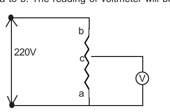
[Figure: A 220 V source across a vertical rheostat with the top end b and the bottom end a; the sliding contact C is one-fourth of the way up from a; a voltmeter V is connected between C and a]
Answer: (B) 40 V
1. Given ac = \( \frac{1}{4} \) ab, so the resistance of the part ac, Rac = \( \frac{1}{4} \) × 12000 = 3000 Ω, and Rbc = 12000 - 3000 = 9000 Ω.
2. The voltmeter (RV = 6000 Ω) is in parallel with the part ac: R' = \( \frac{R_{ac} \times R_V}{R_{ac} + R_V} \) = \( \frac{3000 \times 6000}{3000 + 6000} \) = 2000 Ω.
3. R' and Rbc are in series, so R = 9000 + 2000 = 11000 Ω and the current i = \( \frac{V}{R} \) = \( \frac{220}{11000} \) = 0.02 A.
4. Reading of the voltmeter = p.d. across ac = iR' = 0.02 × 2000 = 40 V, so the correct option is (B).
Teacher's Note:
a) The voltmeter loads the rheostat, so the reading is less than the unloaded 55 V.
b) Find the equivalent of the parallel part first and then use the series current.
Ex.17 (a) Calculate the steady-state current in the 2Ω resistor shown in the circuit in fig. The internal resistance of the battery is negligible and the capacitance of the condenser is 0.2 μF
(b) The resistors, 400Ω and 800Ω are connected in series with a 6 volt battery. It is desired to measure the current in the circuit. An ammeter of 10 ohms resistance is used for this purpose. What will be the reading in the ammeter ? Similarly, if a voltmeter of 10,000 ohms resistance is used to measure the potential difference across the 400 Ω resistor, what will be the reading in the voltmeter ?
[Figure: (a) A 6 V battery and a 2.8 Ω resistor in the bottom wire; across the sides three branches: a 2 Ω resistor, a 3 Ω resistor, and a branch with a 0.2 μF capacitor C and a 4 Ω resistor. (b) First circuit: 400 Ω, 800 Ω, a 10 Ω ammeter A and a 6 V battery in series; second circuit: 400 Ω and 800 Ω in series with a 6 V battery and a 10000 Ω voltmeter V connected across the 400 Ω resistor]
Answer: (a) 0.9 A (b) ammeter 0.00496 A, voltmeter 1.95 V
1. (a) The 2 Ω and 3 Ω resistances are in parallel: \( \frac{1}{R} \) = \( \frac{1}{2} \) + \( \frac{1}{3} \) = \( \frac{5}{6} \), so R = 1.2 Ω.
2. The branch with the capacitor C and the 4 Ω resistance is open circuited for d.c. The total effective resistance of the circuit = 1.2 + 2.8 = 4 Ω.
3. Current in the circuit = \( \frac{6 \text{ V}}{4 \text{ Ω}} \) = 1.5 A. Current through the 2 Ω resistance = 1.2 × \( \frac{3}{5} \) = 0.9 A (currents in parallel resistances are in the ratio of the reciprocals of their resistances).
4. (b) With the ammeter, total resistance = 400 + 800 + 10 = 1210 Ω, so the current = \( \frac{6 \text{ V}}{1210 \text{ Ω}} \) = 0.00496 A.
5. With the voltmeter, 400 Ω and 10000 Ω are in parallel: \( \frac{1}{R} \) = \( \frac{1}{400} \) + \( \frac{1}{10000} \) = \( \frac{26}{10000} \), so R = \( \frac{10000}{26} \) Ω.
6. Total resistance = \( \frac{10000}{26} \) + 800 = \( \frac{30800}{26} \) Ω, so the current = \( \frac{6 \times 26}{30800} \) = \( \frac{156}{30800} \) A.
7. Voltmeter reading = \( \frac{156}{30800} \) × \( \frac{10000}{26} \) = 1.95 V.
Teacher's Note:
a) The printed voltmeter reading 1.96 V is slightly off; the calculation gives 1.948 V, which is 1.95 V.
b) The voltmeter is not ideal, so it reads a little less than the true 1.97 V across the 400 Ω resistor.
c) The ammeter case is a separate circuit from the voltmeter case.
Ex.18 For the fig. Calculate the current through 3 ohm resistor and power dissipated in the entire circuit. The emf of battery is 2 volt and its internal resistance is 2/3 ohm.
[Figure: A 2 V battery (internal resistance 2/3 Ω) connected across a network between A and B: a 3 Ω resistor along the top from A to B, a 6 Ω resistor along the bottom from A to B, and a middle section in which 2 Ω and 4 Ω resistors cross from the left corners to the central point C and 4 Ω and 8 Ω resistors cross from C to the right corners]
Answer: Current through the 3 Ω resistor = 0.44 A; power dissipated in the entire circuit = 2 W
1. The diagram can be redrawn: between A and C the 2 Ω and 4 Ω are in parallel, \( \frac{1}{R_{AC}} \) = \( \frac{1}{2} \) + \( \frac{1}{4} \) = \( \frac{3}{4} \), so RAC = \( \frac{4}{3} \) Ω.
2. Between C and B the 4 Ω and 8 Ω are in parallel, \( \frac{1}{R_{CB}} \) = \( \frac{1}{4} \) + \( \frac{1}{8} \) = \( \frac{3}{8} \), so RCB = \( \frac{8}{3} \) Ω.
3. RACB = \( \frac{4}{3} \) + \( \frac{8}{3} \) = 4 Ω. Between the end points X and Y the resistances 3 Ω, 4 Ω and 6 Ω are in parallel: \( \frac{1}{R_{XY}} \) = \( \frac{1}{3} \) + \( \frac{1}{4} \) + \( \frac{1}{6} \) = \( \frac{9}{12} \), so RXY = \( \frac{4}{3} \) Ω.
4. Total resistance of the circuit = \( \frac{4}{3} \) + \( \frac{2}{3} \) = 2 Ω (including the internal resistance), so the current = \( \frac{2}{2} \) = 1 A.
5. Power dissipated in the circuit = i2R = 1 × 2 = 2 W. P.d. between X and Y = 1 × \( \frac{4}{3} \) = \( \frac{4}{3} \) V, so the current in the 3 Ω resistor = \( \frac{4/3}{3} \) = \( \frac{4}{9} \) = 0.44 A.
Teacher's Note:
a) The total power includes the heat produced in the internal resistance of the battery.
b) All the parallel branches have the same p.d. of 4/3 V across them.
c) Redraw the diagram with the junction names before combining resistances.
Redrawn circuit for Ex.18 (as in the PDF): the 3 Ω and 6 Ω resistors join X and Y; between them 2 Ω and 4 Ω are in parallel from A to C, and 4 Ω and 8 Ω in parallel from C to B; the 2 V battery with internal resistance 2/3 Ω is connected across X and Y.
Ex.19 Two points A and B are maintained at a constant potential difference of 110 volt. A third point is connected to A by two resistances of 100 and 200 ohm in parallel, and to B by a single resistance of 300 ohm. Find the current in each resistance and the potential difference between A and C and between C and B.
[Figure: A triangle ACB with a 110 V source in the side AB; the side AC consists of 100 Ω and 200 Ω resistors in parallel (currents i1 and i - i1) and the side CB is a single 300 Ω resistor carrying the current i]
Answer: 100 Ω: 0.2 A; 200 Ω: 0.1 A; 300 Ω: 0.3 A; VAC = 20 V and VCB = 90 V
1. Let the current i flow through the 300 Ω resistance; it divides at C into i1 in the 100 Ω and (i - i1) in the 200 Ω.
2. Second law for the parallel loop: i1 × 100 - (i - i1) × 200 = 0, so 300 i1 - 200 i = 0 ......(1)
3. Second law for the loop through the 110 V source: (i - i1) × 200 + i × 300 = 110, so 500 i - 200 i1 = 110 ......(2)
4. Solving (1) and (2): i = \( \frac{3}{10} \) A and i1 = \( \frac{1}{5} \) A. So 100 Ω: 0.2 A, 200 Ω: 0.1 A and 300 Ω: 0.3 A.
5. VA - VC = 0.2 × 100 = 20 V, and VC - VB = 0.3 × 300 = 90 V.
Teacher's Note:
a) Check: 20 V + 90 V = 110 V.
b) The p.d. across the 100 Ω and the 200 Ω is the same, 20 V.
Ex.20 In the circuit shown in fig. E, F, G and H are cells of emf 2, 1, 3 and 1 volts and their internal resistances are 2, 1, 3 and 1 ohm respectively. Calculate -
(i) the potential difference between B and D and
(ii) the potential difference across the terminals of each of the cells G and H.
[Figure: A square ABCD with A at the top left, B at the top right, C at the bottom right and D at the bottom left. Cell E (2 V, 2 Ω) is in the side AB, cell H (1 V, 1 Ω) in the side BC, cell G (3 V, 3 Ω) in the side DC and cell F (1 V, 1 Ω) in the side AD; a 2 Ω resistor joins D to B along the diagonal. The polarities are marked with + and - signs on each cell]
Answer: (i) VB - VD = 2/13 V ≈ 0.15 V (ii) across G: 21/13 = 1.61 V; across H: 19/13 = 1.46 V
1. Let i flow from A to D through the cell F branch, i2 from D to C through the cell G branch, and i1 from B to D along the 2 Ω diagonal. At D: i + i1 = i2 ......(A)
2. Mesh ADBA: i × 1 - 2i1 + 2i = -1 + 2, so 3i - 2i1 = 1 ......(B)
3. Mesh DCBD: 3i2 + i2 + 2i1 = 3 - 1, so 4i2 + 2i1 = 2 ......(C)
4. Solving (A), (B) and (C): i1 = \( \frac{1}{13} \) A, i2 = \( \frac{6}{13} \) A and i = \( \frac{5}{13} \) A.
5. (i) P.d. between B and D = 2i1 = 2 × \( \frac{1}{13} \) = \( \frac{2}{13} \) V.
6. (ii) The cell G delivers i2, so its terminal p.d. = E - i2r = 3 - \( \frac{6 \times 3}{13} \) = 1.61 V. The cell H carries i2 against its emf (it is being charged), so its terminal p.d. = 1 + \( \frac{6}{13} \) × 1 = 1.46 V.
Teacher's Note:
a) The cell H is charged by the current from G, which is why its terminal voltage is greater than its emf.
b) A cell supplying current has terminal voltage E - ir; a cell being charged has E + ir.
c) Check: 0.154 V + 1.46 V = 1.62 V, equal to the p.d. across G (21/13 V).
Ex.21 In the adjoining circuit diagram each resistance is of 10Ω. The current in the arm AD will be-
(A) 2i/5
(B) 3i/5
(C) 4i/5
(D) i/5
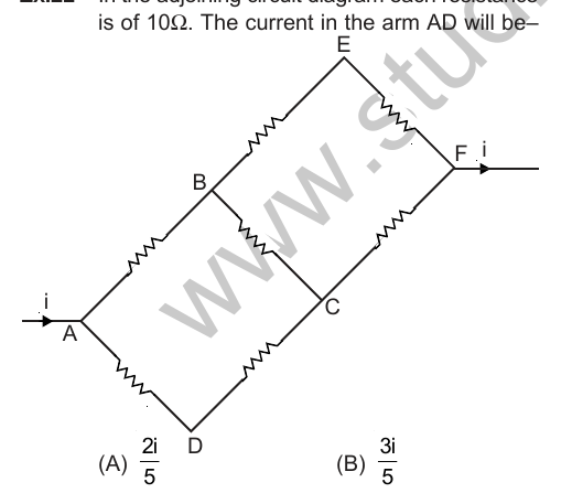
[Figure: A network with the current i entering at A and leaving at F. Resistors of 10 Ω each: A to B, B to E, E to F, A to D, D to C, C to F and B to C]
Answer: (A) 2i/5
1. Let the current i enter at A. Let i1 flow in the path A to D to C, i2 flow in the arm BC, so the current in AB is (i - i1), in B to E to F is (i - i1 - i2) and in CF is (i1 + i2).
2. Mesh ABCDA: 10(i - i1) + 10i2 - 20i1 = 0, so -3i1 + i2 = -i ......(A)
3. Mesh BEFCB: 20(i - i1 - i2) - 10(i1 + i2) - 10i2 = 0, so -3i1 - 4i2 = -2i ......(B)
4. From (A) and (B): i1 = \( \frac{2i}{5} \) and i2 = \( \frac{i}{5} \).
5. So the current in the arm AD is iAD = \( \frac{2i}{5} \), which is option (A).
Teacher's Note:
a) The arm A to D to C contains two resistances, so its voltage drop is 20 i1.
b) Check the answer with the loop ABCDA: 10 × 3i/5 + 10 × i/5 - 20 × 2i/5 = 0.
Ex.22 What is the equivalent resistance between the terminal points A and B in the network shown in fig. Assume that the resistance of each resistor is 10Ω.
[Figure: A ladder-type network of equal resistors R between A and B: a top wire A - C - D - F with a resistor R from C to D and a resistor R from D to F; vertical resistors R from C to G, from D to H and from F to K; a bottom wire G - H - K - B with a resistor R from G to H and from H to K; the currents I, I1, I2 are marked and an imaginary battery E is connected between A and B]
Answer: 14 Ω
1. Let a battery of e.m.f. E and no internal resistance be connected across A and B, and let I enter at the corner C and leave at the corner B. The currents are distributed as in the figure by Kirchhoff's first law.
2. Loop CDHGC: -RI1 - R(I1 - I2) + 2R(I - I1) = 0, so 4I1 - I2 = 2I ......(A)
3. Loop DFKHD: -2RI2 + R(I - I2) + R(I1 - I2) = 0, so -I1 + 4I2 = I ......(B)
4. Solving (A) and (B): I1 = \( \frac{3}{5} \) I and I2 = \( \frac{2}{5} \) I ......(C)
5. Loop ACGHKBEA: -2(I - I1)R - (I - I2)R + E = 0, so E = 2(I - I1)R + (I - I2)R = 2 × \( \frac{2}{5} \) IR + \( \frac{3}{5} \) IR = \( \frac{7}{5} \) IR.
6. RAB = \( \frac{E}{I} \) = \( \frac{7}{5} \) R = \( \frac{7}{5} \) × 10 = 14 Ω.
Teacher's Note:
a) The printed working writes 2(I - I1)R with the first bracket in the loop equation (E); the value 7R/5 is correct.
b) The result can be checked by reducing the ladder in the usual way: it gives 14 Ω.
Ex.23 Twelve equal wires, each of resistance R ohm are connected so as to form a skeleton cube. An electric current enters this cube from one corner and leaves out the diagonally opposite corner. Calculate the total resistance of this assembly.
[Figure: A skeleton cube of twelve wires with the battery E connected between the diagonally opposite corners A and G; currents I/3 in the three wires leaving A, I/6 in the six middle wires and I/3 in the three wires reaching G are marked]
Answer: Rtotal = \( \frac{5}{6} \) R
1. Let ABCDEFGH be the skeleton cube of twelve equal wires. Connect a battery of e.m.f. E across A and G, and let the total current I enter at A and leave at G.
2. By symmetry the current divides as I/3 in each of the three wires from A, then I/6 in each of the six middle wires, and I/3 in each of the three wires into G.
3. Applying Kirchhoff's second law to the mesh ADCGEA: -\( \frac{1}{3} \) IR - \( \frac{1}{6} \) IR - \( \frac{1}{3} \) IR + E = 0.
4. E = \( \frac{5}{6} \) IR.
5. Rtotal = \( \frac{E}{I} \) = \( \frac{5}{6} \) R.
Teacher's Note:
a) By symmetry the three corners next to A are at the same potential, and so are the three corners next to G.
b) The three groups in series are R/3, R/6 and R/3, whose sum is 5R/6.
Ex. 24 Twelve equal wires each of resistance R are joined to form a skeleton cube. Find the resistance between two corners on the same edge of the cube.
[Figure: A skeleton cube ABCDEFGH with the battery E connected across the edge AB. The currents x + 2y at A, x in AB, y in AD and AH, y - z and z in the other edges are marked]
Answer: RAB = \( \frac{7}{12} \) R
1. Let I = x + 2y be the current entering at A when a battery of e.m.f. E and no internal resistance is connected across the edge AB. The edges AD and AH are symmetrically connected to A and carry equal currents y; the edge AB carries x.
2. RAB I = E, so E = RAB (x + 2y) ......(A). Applying the second law to the mesh containing AB and the cell, Rx = E ......(B).
3. Mesh AHEB: yR + zR + yR - xR = 0, so x - 2y - z = 0 ......(C)
4. Mesh DGFC: (y - z)R + 2(y - z)R - zR = 0... which gives 4y = 5z, i.e. z = \( \frac{4}{5} \) y ......(D)
5. Substituting in (C): x - 2y - \( \frac{4}{5} \) y = 0, so y = \( \frac{5}{14} \) x.
6. From (A) and (B): E = RAB \( \left( x + \frac{10}{14} x \right) \) = R x, so RAB = \( \frac{14}{24} \) R = \( \frac{7}{12} \) R.
Teacher's Note:
a) The same result follows from superposition of the two cube problems, and it matches the result of Ex.45 in the theory section.
b) The edge resistance of a cube is always 7R/12.
Ex.25 Eleven equal wires each of resistance 2Ω form the edges of an incomplete skeleton cube. Find the total resistance between points A and B of the vacant edge.
[Figure: A skeleton cube with the wire AB missing: eleven wires of 2 Ω each; the current I enters at A and leaves at B, with the branch currents (I/2, I1, I/2 - I1 and so on) marked on the edges and an imaginary battery E' joined between A and B]
Answer: RAB = \( \frac{7}{5} \) R = 2.8 Ω
1. Let a battery of e.m.f. E' be applied between A and B, and let a current I1 enter at A. Let RAB be the equivalent resistance, so RAB I1 = E'.
2. The currents, by symmetry, are shown in the figure: I/2 in each of the two wires out of A, with the remaining wires carrying I/2 - I1 and so on.
3. Second law for the mesh DGFC: \( \left( \frac{1}{2} - I_1 \right) \) R + (I - 2I1) R + R \( \left( \frac{1}{2} - I_1 \right) \) - I1R = 0, so 2I - 5I1 = 0 and I1 = \( \frac{2}{5} \) I.
4. For the outer path AHEBE': \( \frac{1}{2} \) R + I1 R + \( \frac{1}{2} \) R = E'. Using I1 = 2I/5: IR + \( \frac{2}{5} \) IR = \( \frac{7}{5} \) IR = E'.
5. RAB = \( \frac{E'}{I} \) = \( \frac{7}{5} \) R = \( \frac{7}{5} \) × 2 = 2.8 Ω.
Teacher's Note:
a) The printed answer 2.4 Ω is an arithmetic slip; (7/5) × 2 = 2.8 Ω.
b) Check: the complete cube has 7R/12 across an edge. With that wire removed, 12/(7R) = 1/RAB + 1/R gives RAB = 7R/5.
Ex.26 Three 4V batteries, internal resistances 0.1, 0.2 and 0.3 Ω are connected in parallel and in series with a 2.045 ohm resistor. Find (a) the equivalent resistance of the circuit (b) the equivalent voltage (c) the current in the circuit (d) the terminal voltage for equivalent cells (e) the terminal voltage of each cell.
[Figure: Three 4 V cells with series internal resistances of 0.1 Ω, 0.2 Ω and 0.3 Ω connected in parallel between the points A and B, and a 2.045 Ω resistor joining A and B in the outer circuit]
Answer: (a) 2.1 Ω (b) 4 V (c) 1.9 A (d) 3.895 V (e) 3.895 V
1. The batteries are in parallel, so the total emf of the circuit is 4 V. The resistance of the combination: \( \frac{1}{R_{AB}} \) = \( \frac{1}{0.1} \) + \( \frac{1}{0.2} \) + \( \frac{1}{0.3} \) = \( \frac{110}{6} \), so RAB = \( \frac{6}{110} \) = 0.055 Ω.
2. (a) Equivalent resistance of the circuit R = RAB + 2.045 = 0.055 + 2.045 = 2.1 Ω.
3. (b) Equivalent voltage = 4 V.
4. (c) Current in the circuit = \( \frac{4}{2.1} \) = 1.9 A.
5. (d) Terminal voltage of the equivalent cell = 4 - iRAB = 4 - 1.9 × 0.055 = 3.8955 V (about 3.895 V).
6. (e) The batteries are in parallel, so the terminal voltage of each cell is the same, 3.895 V.
Teacher's Note:
a) The terminal voltage can also be found as i × 2.045 = 3.895 V.
b) The printed working has a typing slip (4 - 1.9 × 0.55); the correct product is 1.9 × 0.055 = 0.1045.
c) All cells in parallel share the same terminal voltage.
Ex. 27 In the fig below the bulbs are identical, which bulb(s), light(s) most brightly ?
(A) 1 only
(B) 4 only
(C) 2 and 3
(D) 1 and 5.
Answer: (D) 1 and 5.
1. Since all bulbs are identical they have the same resistance.
2. The current I flowing through bulb 1 branches at A, so the currents in bulbs 2 and 3 and in bulb 4 are less than I.
3. The current through bulb 5 is also I. Thus bulbs 1 and 5 glow equally brightly, and more than bulbs 2, 3 or 4.
4. Hence, the correct option is (D).
Teacher's Note:
a) The figure of this example is not printed in the source; the reasoning above uses the current flow described in its solution.
b) Brightness depends on the power I2R, so the bulbs with the largest current are the brightest.
Ex. 28 An electric tea kettle has two heating coils. When one the coils is switched on, the kettle begins to boil in 6 minutes. When the other is switched on, the boiling begins in 8 minutes. In what time will the boiling begin if both coils are switched on simultaneously (i) in series (ii) in parallel ?
(A) 14 min, 3.43 min
(B) 12 min, 3.43min
(C) 3.43 min, 12 min
(D) 3.43 min, 14 min.
Answer: (A) 14 min, 3.43 min
1. Let R1 and R2 be the resistances of the coils, V the supply voltage and Q the heat required to boil the water.
2. Q = \( \frac{V^2 t_1}{J R_1} \) = \( \frac{V^2 \times 6 \times 60}{4.2 R_1} \) cal and Q = \( \frac{V^2 \times 8 \times 60}{4.2 R_2} \) cal. Equating, \( \frac{6}{R_1} \) = \( \frac{8}{R_2} \), so R2 = \( \frac{4}{3} \) R1.
3. (i) In series, R' = R1 + R2 = \( \frac{7}{3} \) R1, so t' = \( \frac{7}{3} \) × 6 × 60 s = 14 min.
4. (ii) In parallel, R'' = \( \frac{R_1 R_2}{R_1 + R_2} \) = \( \frac{4}{7} \) R1, so t'' = \( \frac{4}{7} \) × 6 × 60 s = 3.43 min.
5. Hence, the correct option is (A).
Teacher's Note:
a) The time to boil is proportional to the resistance at constant voltage.
b) Resistances in series add, so the time adds: 6 + 8 = 14 min.
Ex.29 A 10 m long nichrome wire having 80Ω resistance, has current carrying capacity of 5 A. What is the power which can be obtained as heat by the wire from a 200 V mains supply ? If the wires are cut in two equal parts and connected in such a way that it gives maximum power. What is the arrangement to obtain maximum power ? (Rohilkhand Univ.)
(A) 50 W, 200 W
(B) 500 W, 2000 W
(C) 50 W, 100 W
(D) 500 W, 1000 W
Answer: (B) 500 W, 2000 W
1. If the wire is connected across the battery, the current I = \( \frac{V}{R} \) = \( \frac{200}{80} \) = 2.5 A and the power P = \( \frac{V^2}{R} \) = \( \frac{200 \times 200}{80} \) = 500 W.
2. The wire can carry a maximum current of 5 A. To double the current, the resistance should be halved. If the wire is divided into two parts and the two parts are connected in parallel across the 200 V mains, the resistance of each part is 40 Ω, so the current in each part = \( \frac{200}{40} \) = 5 A.
3. Net resistance R' = \( \frac{40 \times 40}{40 + 40} \) = 20 Ω and the new power Pmax = \( \frac{V^2}{R'} \) = \( \frac{200 \times 200}{20} \) = 2000 W.
4. Hence, the maximum power is 2000 W, obtained when the wire is cut into two halves and the halves are connected in parallel across the supply.
Teacher's Note:
a) For the same voltage, power is greater when the resistance is smaller.
b) The 5 A limit is met in each half, so the halves in parallel are the best arrangement.
Ex. 30 A heating-coil of 2000 watt is immersed in an electric kettle. The time taken in raising the temperature of 1 litre of water from 4ºC to 100ºC will be- (Only 80% part of the thermal energy produced is used in raising the temperature of water.)
(A) 252 s
(B) 250 s
(C) 245 s
(D) 247 s
Answer: (A) 252 s
1. The relation between work and heat produced is W = JH, so P t × \( \frac{80}{100} \) = J m s Δθ.
2. \( \frac{80}{100} \) × 2000 × t = 4.2 × 1000 × 1 × (100 - 4), where the mass of 1 litre of water is 1000 g and its specific heat is 1 cal g-1 °C-1.
3. t = \( \frac{4.2 \times 1000 \times 96 \times 100}{2000 \times 80} \) = 252 s.
4. Hence, the correct option is (A).
Teacher's Note:
a) Only 80% of the supplied energy heats the water, so the useful power is 0.8 × 2000 = 1600 W.
b) Heat needed = 1000 × 96 = 96000 cal = 4.03 × 10⁵ J.
Ex. 31 In the following figure the rate of heat generated in 2 ohm resistor and potential differents across 6 ohm resister will be respectively - (Heat generated in 5 ohm resistor due to current flowing in it is 45 J/s)
(A) 32 J/s, 6V
(B) 16 J/s, 3V
(C) 8 J/s, 1V
(D) 64 J/s, 12V
[Figure: A current i enters through a 2 Ω resistor at the point A; from A an upper branch with 6 Ω and 9 Ω resistors in series (current i1) and a lower branch with a 5 Ω resistor (current i2) meet again at the point D, where the current continues towards B]
Answer: (A) 32 J/s, 6 V
1. Let the current in the 5 Ω resistor be i2. P = i22 R2, so 45 = i22 × 5 and i2 = 3 A.
2. The upper branch (6 Ω + 9 Ω = 15 Ω) and the 5 Ω branch are in parallel: \( \frac{i_1}{i_2} \) = \( \frac{5}{15} \) = \( \frac{1}{3} \), so i1 = 1 A.
3. The total current through the 2 Ω resistor is i = i1 + i2 = 4 A.
4. The rate of heat generation in the 2 Ω resistor = i2R = 42 × 2 = 32 J/s.
5. Potential difference across the 6 Ω resistor = i1 × 6 = 1 × 6 = 6 V, so the correct option is (A).
Teacher's Note:
a) The branch currents in a parallel combination are in the inverse ratio of the branch resistances.
b) The 2 Ω resistor carries the sum of the two branch currents.
Ex. 32 A 220 volt 100 watt bulb is connected to a 110 volt source. The power consume by the bulb will be -
(A) 25 W
(B) 20 W
(C) 484 W
(D) 120 W
Answer: (A) 25 W
1. Resistance of the bulb R = \( \frac{V^2}{P} \) = \( \frac{220 \times 220}{100} \) = 484 Ω.
2. The new power for the voltage of 110 V is P' = \( \frac{V'^2}{R} \) = \( \frac{110 \times 110}{484} \) = 25 W.
3. Hence, the correct option is (A).
Teacher's Note:
a) Power varies as the square of the voltage when the resistance is constant: halving the voltage reduces the power to one-fourth.
b) The actual filament is cooler at 110 V, so the true value is slightly higher; the standard answer assumes constant resistance.
Ex.33 An electric motor whose resistance is 2 ohm is started with a supply of 110 volt. It takes 10 ampere current at its full speed. The electric power consumed and part of the power used in mechanical work will be respectively-
(A) 900 W, 82%
(B) 800 W, 80%
(C) 200 W, 62%
(D) None of the above.
Answer: (A) 900 W, 82%
1. Power of the motor = VI = 110 × 10 = 1100 W.
2. Heat loss in the motor = i2R = (10)2 × 2 = 200 W.
3. Power converted to mechanical work = 1100 - 200 = 900 W.
4. Percentage of the total power consumed in mechanical work = \( \frac{900}{1100} \) × 100 = 82% (approx.).
5. Hence, the correct option is (A), taking the mechanical power as 900 W.
Teacher's Note:
a) The question asks for the power consumed (1100 W) and the part used as mechanical work (900 W, 82%); option (A) gives the useful power and the percentage.
b) Power lost as heat in the winding is i2R.
Ex. 34 A copper wire having cross-sectional area 0.5 mm2 and a length of 0.1 m is initially at 25º C and is thermally insulated from the surroundings. If a current of 10 A is set up in this wire,
(i) Find the time in which the wire will start melting. The change of resistance with temperature of the wire may be neglected.
(ii) What will be the time taken if the length of the wire is doubled ? Giving for copper, density = 9 × 10³ kg/m3, specific heat = 9 × 10⁻² Kilocal kg-1 (ºC)-1, melting point = 1075 ºC, specific resistance = 1.6 × 10⁻⁸ ohm-metre.
Answer: (i) t ≈ 558 s (ii) the same, 558 s
1. R = \( \frac{ρ ℓ}{A} \), where ℓ = 0.1 m and A = 0.5 mm2 = 0.5 × 10⁻⁶ m2. If Q is the heat required to melt the copper wire, then Q = i2Rt / J kilocal ......(A)
2. Also Q = m s Δθ = (A ℓ d) s Δθ kilocal ......(B), where Δθ = 1075 - 25 = 1050 ºC.
3. Equating (A) and (B): \( \frac{i^2 R t}{J} \) = A ℓ d s Δθ, so t = \( \frac{J A ℓ d s Δθ}{i^2 R} \) = \( \frac{J A^2 d s Δθ}{i^2 ρ} \).
4. t = \( \frac{4.2 \times 10^{3} \times (0.5 \times 10^{-6})^2 \times (9 \times 10^{3}) \times (9 \times 10^{-2}) \times 1050}{(10)^2 \times 1.6 \times 10^{-8}} \) ≈ 558 s.
5. (ii) The length ℓ cancels in the expression for t, so the time is independent of the length of the wire. On doubling the length, the time remains the same, 558 s.
Teacher's Note:
a) The printed value 588.14 s is an arithmetic slip; the substitution gives 558.14 s.
b) Doubling the length doubles both the heat produced (R doubles) and the mass to be heated, so the time does not change.
c) Use J = 4.2 × 10³ joule per kilocalorie, since the specific heat is in kilocalories.
Ex.35 A person decide to use his bath-tub water to generate electric power to run a 40 W bulb. The bath tub is located at a height of 10 m from the ground and it holds 20 litres of water. He installs a water driven wheel generator on the ground. The rate at which he should drain the water from the bath tub to light the bulb and the time he keeps the bulb on will be respectively- (The efficiency of the generator is 90%) (g = 9.8 m/s2)
(A) 0.345 kg/s, 441s
(B) 40 kg/s, 100 s
(C) 0.454 kg/s, 441s
(D) None of these
Answer: (D) None of these (rate 0.454 kg/s, time 44.1 s)
1. Rate of loss of potential energy × efficiency = electric power generated: \( \frac{dm}{dt} \) × g h × \( \frac{90}{100} \) = 40 W.
2. \( \frac{dm}{dt} \) = \( \frac{40 \times 100}{90 \times 9.8 \times 10} \) = 0.454 kg/s.
3. The tub holds 20 litres, i.e. 20 kg of water, so the time the bulb stays on = \( \frac{20 \text{ kg}}{0.454 \text{ kg/s}} \) = 44.1 s.
4. A rate of 0.454 kg/s with a time of 44.1 s is not given in options (A), (B) or (C), so the correct option is (D).
Teacher's Note:
a) The printed key (C) 0.454 kg/s, 441 s is obtained with 200 litres of water; for 200 litres the time is 441 s, and then option (C) would be correct.
b) The rate depends only on the power, the height and the efficiency, not on the quantity of water.
Ex.36 A wire of resistance 0.1 ohm cm-1 bent to form a square ABCD of side 10 cm. A similar wire is connected between B and D to form the diagonal BD. Find the effective resistance between points A and C. If a 2 V battery of negligible internal resistance is connected across A and C calculate the total power dissipated.
[Figure: A square ABCD with A at the bottom left, B at the top left, C at the top right and D at the bottom right, each side being a resistor of 1 Ω (10 cm of wire), and a diagonal wire joining B and D]
Answer: RAC = 1 Ω; power dissipated = 4 W
1. The resistance of each side of the square = 10 × 0.1 = 1 Ω. The square forms a Wheatstone bridge, since \( \frac{P}{Q} \) = \( \frac{R}{S} \) is satisfied, so no current flows through BD.
2. The path ABC has resistance 1 + 1 = 2 Ω and the path ADC has resistance 1 + 1 = 2 Ω; they are in parallel between A and C.
3. \( \frac{1}{R} \) = \( \frac{1}{2} \) + \( \frac{1}{2} \), so R = 1 Ω.
4. With a 2 V battery connected across A and C, the current i = \( \frac{E}{R} \) = \( \frac{2}{1} \) = 2 A.
5. Power dissipated P = E i = 2 × 2 = 4 W.
Teacher's Note:
a) The diagonal BD carries no current, so its length (10√2 cm) does not matter.
b) Power can also be found from P = E2/R = 4/1 = 4 W.
Ex.37 Three equal resistors connected in series across a source of emf together dissipate 10 watt of power. What would be the power dissipated if the same resistors are connected in parallel across the same source of emf
Answer: 90 W
1. Let R be the resistance of each resistor. In series the total resistance is R + R + R = 3R, so the power dissipated W1 = \( \frac{E^2}{3R} \), where E is the emf of the source.
2. In parallel, \( \frac{1}{R'} \) = \( \frac{1}{R} \) + \( \frac{1}{R} \) + \( \frac{1}{R} \) = \( \frac{3}{R} \), so R' = \( \frac{R}{3} \) and the power dissipated is W2 = \( \frac{E^2}{R/3} \) = \( \frac{3E^2}{R} \).
3. \( \frac{W_2}{W_1} \) = \( \frac{3E^2}{R} \) × \( \frac{3R}{E^2} \) = 9, so W2 = 9 W1 = 9 × 10 = 90 W.
Teacher's Note:
a) At a fixed emf, power is inversely proportional to the equivalent resistance.
b) The parallel resistance is one-ninth of the series resistance, so the power is nine times larger.
Ex.38 Two bulbs rated at 25 watts, 110 volts of 100 watts, 110 volts are connected in series across 220 volts electric supply. Perform the necessary calculations to find out which of the two bulbs, if any, will fuse. What would happen if the two bulbs were connected in parallel to the same supply.
Answer: In series, the 25 W bulb will fuse. In parallel, both bulbs will fuse.
1. Let i1 and i2 be the currents which can flow safely through the two lamps: i1 = \( \frac{25}{110} \) = 0.227 A and i2 = \( \frac{100}{110} \) = 0.909 A.
2. The resistances of the two bulbs are R1 = \( \frac{110}{0.227} \) = 484 Ω and R2 = \( \frac{110}{0.909} \) = 121 Ω.
3. In series, the total resistance R = 484 + 121 = 605 Ω, so the current from the 220 V supply is i = \( \frac{220}{605} \) = 0.363 A.
4. This current is more than the safe current of the 25 W bulb (0.227 A) but less than that of the 100 W bulb (0.909 A), so the 25 W bulb will fuse.
5. In parallel, the effective resistance R' is given by \( \frac{1}{R'} \) = \( \frac{1}{R_1} \) + \( \frac{1}{R_2} \) = \( \frac{1.136}{110} \), so R' = \( \frac{110}{1.136} \) Ω and the current i' = \( \frac{220}{R'} \) = \( \frac{220 \times 1.136}{110} \) = 2.27 A.
6. Let i3 and i4 be the currents in the two bulbs. The p.d. across both is the same: i3R1 = i4R2, so \( \frac{i_3}{0.227} \) = \( \frac{i_4}{0.909} \), i.e. 4i3 = i4 ......(A), and i3 + i4 = 2.27 ......(B).
7. Solving (A) and (B): i3 = 0.454 A and i4 = 1.82 A. Each is more than the safe current of its bulb, so both bulbs will fuse.
Teacher's Note:
a) Rated voltage 110 V is applied at once to each bulb when they are in parallel across 220 V, so each bulb gets double its rated voltage.
b) In series the bulb with the greater resistance (the 25 W bulb) takes the greater share of the voltage.
c) Safe current = rated power / rated voltage.

Please click on below link to download pdf file for CBSE Class 12 Physics Current Electricity Solved Examples.
Free study material for Physics
CBSE Class 12 Physics Study Material: Chapter 03 Current Electricity
Quick Revision Material for Chapter 03 Current Electricity
Access comprehensive study material for Chapter 03 Current Electricity, including revision notes, concept maps, and high-probability questions. These resources are designed in alignment with the latest 2026 CBSE syllabus for Class 12 Physics to support effective exam preparation.
Expert Notes and Solved Exam Questions
Built using official NCERT guidelines for Class 12 Physics, these materials provide reliable academic support. Integrating past examination questions and step-by-step solutions helps students understand official CBSE grading criteria.
Additional Study Resources for Class 12
Wrap up your chapter revision by testing your knowledge against standard objective question formats. Explore our full library of free, up-to-date sample papers and online assessments to secure top grades in your CBSE examinations.
FAQs
Our advanced study package for Chapter 03 Current Electricity includes detailed concepts, diagrams, Mind Maps, and explanation of complex topics to ensure Class 12 students learn as per syllabus for 2026 exams.
The Mind Maps provided for Chapter 03 Current Electricity act as visual anchors which will help faster recall during high-pressure exams.
Yes, teachers use our Class 12 Physics resources for lesson planning as they are in simple language and have lot of solved examples.
Yes, You can download the complete, mobile-friendly PDF of the Physics Chapter 03 Current Electricity advanced resources for free.
Yes, our subject matter experts have updated the Chapter 03 Current Electricity material to align with the rationalized NCERT textbooks and have removed deleted topics and added new competency-based questions.