

Class 12 Physics Study Guide: CBSE Class 12 Physics Alternating Current Exam Notes
Review targeted academic resources with the CBSE Class 12 Physics Alternating Current Exam Notes. Built according to official CBSE standards for the 2026-27 term, these downloadable Class 12 Physics study materials support effective daily practice and deeper conceptual understanding for Chapter 07 Alternating Current.
Download Chapter 07 Alternating Current Study Material PDF
View or download the dedicated CBSE Class 12 Physics Alternating Current Exam Notes resource below. Engaging with these advanced study guides under focused conditions ensures continuous academic progress and mastery of the 2026-27 curriculum for Chapter 07 Alternating Current.
CBSE Class 12 Physics Alternating Current Exam Notes. Please refer to the examination notes which you can use for preparing and revising for exams. These notes will help you to revise the concepts quickly and get good marks.

Class 12 Physics: Alternating Current Exam Notes
Alternating Current and Voltage
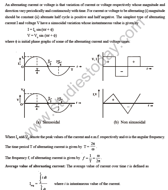
An alternating current or voltage is that variation of current or voltage respectively whose magnitude and direction vary periodically and continuously with time. For current or voltage to be alternating (i) magnitude should be constant (ii) alternate half cycle is positive and half negative. The simplest type of alternating current \(I\) and voltage \(V\) have a sinusoidal variation whose instantaneous value is given by
\[I = I_0\sin(\omega t+\phi)\]
\[V = V_0\sin(\omega t+\phi)\]
where \(\phi\) is the initial phase. Graphs of some of the alternating current and voltage cases:
Where \(I_0\) and \(V_0\) denote the peak values of the current and e.m.f. respectively and \(\omega\) is the angular frequency.
The time period \(T\) of alternating current is given by \(T = \dfrac{2\pi}{\omega}\).
The frequency \(f\) of alternating current is given by \(f = \dfrac{1}{T} = \dfrac{\omega}{2\pi}\).
Average value of alternating current: The average value of current over time \(t\) is defined as
\[I_{avg} = \frac{\int_0^t i\,dt}{\int_0^t dt}\]
where \(i\) is the instantaneous value of the current.
For sinusoidal variation of current and voltage:
Case I: Average value over a complete cycle
\[I_{avg} = \frac{\int_0^T i_0\sin(\omega t+\phi)\,dt}{\int_0^T dt} = 0\]
Similarly \(V_{avg} = 0\).
Case II: Average value over a half cycle
\[i_{avg} = \frac{\int_0^{T/2} i_0\sin\omega t\,dt}{\int_0^{T/2} dt} = \frac{2I_0}{\pi}\]
Similarly \(V_{avg} = \dfrac{2V_0}{\pi}\).
Effective Current and Voltage: Since the average value over a time period of sinusoidal alternating current or voltage is zero, a D.C. ammeter or voltmeter does not show any deflection for alternating current circuits. Therefore alternating current ammeters or voltmeters are used, which measure the average or effective values of the current and voltage and are based on measuring the root mean square values of current and voltage. The root mean square value of an alternating current is that steady current which when passed through a resistor will produce the same amount of heat as the actual alternating current shall develop when passed for the same time. It is denoted by \(I_{rms}\).
The magnitude of \(I_{rms}\) is given by
\[I_{rms}^2 = \frac{\int_0^T I^2\,dt}{\int_0^T dt} = \frac{\int_0^T I_0^2\sin^2(\omega t)\,dt}{\int_0^T dt} = \frac{I_0^2}{2}\]
\[\therefore\ I_{eff} = I_{rms} = \frac{I_0}{\sqrt{2}} = 0.707\,I_0\]
where \(I_0\) is the peak value of the current.
Similarly \(V_{eff} = V_{rms} = \dfrac{V_0}{\sqrt{2}} = 0.707\,V_0\).
Power in Alternating Current Circuit:
Average power in an alternating current circuit over time \(t\) is defined as
\[P_{avg} = \frac{\int_0^t V i\,dt}{\int_0^t dt}\]
where \(V\) and \(i\) are instantaneous values of voltage and current respectively. Let \(V = V_0\sin\omega t\) and \(i = i_0\sin(\omega t-\phi)\). Average power over a cycle:
\[P_{avg} = \frac{\int_0^T V_0 i_0\sin\omega t\,\sin(\omega t-\phi)\,dt}{\int_0^T dt} = \frac{V_0 i_0\int_0^T\left(\sin^2\omega t\cos\phi-\tfrac{1}{2}\sin 2\omega t\sin\phi\right)dt}{T}\]
\[= \tfrac{1}{2}V_0 i_0\cos\phi = V_{rms}\,i_{rms}\cos\phi\]
The term \(\cos\phi\) is known as the power factor.
It is said to be leading if current leads voltage, lagging if current lags voltage. Thus, a power factor of 0.5 lagging means the current lags the voltage by \(60^\circ\) (as \(\cos^{-1}0.5 = 60^\circ\)). The product of \(V_{rms}\) and \(i_{rms}\) gives the apparent power. The true power is obtained by multiplying the apparent power by the power factor \(\cos\phi\). Thus,
Apparent power = \(V_{rms}\times i_{rms}\)
and True power = apparent power \(\times\) power factor
For \(\phi = 0^\circ\), the current and voltage are in phase. The power is thus maximum (\(= V_{rms}\times i_{rms}\)). For \(\phi = 90^\circ\), the power is zero. The current is then stated to be wattless. Such a case will arise when the resistance in the circuit is zero, i.e. the circuit is purely inductive or capacitive. The case is similar to that of a frictionless pendulum, where the total work done by gravity upon the pendulum in a cycle is zero.
Alternating current through different circuits
(1) Purely Resistive Circuit :
If \(V = V_0\sin(\omega t)\), then \(I = \dfrac{V}{R} = \dfrac{V_0}{R}\sin(\omega t) = I_0\sin(\omega t)\), and \(\phi = 0\).
Both voltage and current are in the same phase.
Instantaneous power dissipated \(P = VI = V_0I_0\sin^2(\omega t)\).
Average power dissipated over a cycle:
\[\bar{P} = \frac{1}{T}\int_0^T P\,dt = \frac{V_0I_0}{2} = \frac{V_0}{\sqrt{2}}\cdot\frac{I_0}{\sqrt{2}} \ \Rightarrow\ \bar{P} = V_{rms}\cdot I_{rms}\]
(2) Purely Inductive Circuit
Let \(V = V_0\sin\omega t\). Then \(V - L\dfrac{dI}{dt} = 0\), so \(I = I_0\sin(\omega t-\pi/2)\), where \(I_0 = \dfrac{V_0}{\omega L}\ \Rightarrow\ V_{rms} = (\omega L)\,I_{rms}\).
Therefore, in a purely inductive circuit
- the current lags behind the voltage in phase by \(\pi/2\), and
- the quantity \(\omega L\) is a measure of the effective opposition offered to the flow of an alternating current by an inductor. It is denoted by \(X_L\) and is called inductive reactance: \(X_L = \omega L\)
Thus an inductance offers larger opposition to a.c. of higher frequency than to a.c. of lower frequency.
Also the average power consumed by a purely inductive circuit in a cycle is zero: \(P = 0\) since \(\phi = 90^\circ\).
Since the current flows without any power loss, it is called wattless current. During one quarter cycle, when the current increases, energy is stored in the inductance in the form of magnetic energy, and during the next quarter, when the current decreases, this energy is transferred back to the source. An inductance coil with a high value of reactance and low resistance has the property of opposing alternating current without any significant power loss. Such a coil is called a choke coil.
(3) Purely Capacitive Circuit
If \(V = V_0\sin\omega t\), \(Q = CV = CV_0\sin(\omega t)\), then \(I = \dfrac{dq}{dt} = \dfrac{d}{dt}(CV_0\sin\omega t) = \omega CV_0\cos\omega t\)
\(\therefore\ I = I_0\sin(\omega t+\pi/2)\), where \(I_0 = (\omega C)V_0\ \Rightarrow\ V_{rms} = \left(\dfrac{1}{\omega C}\right)I_{rms}\).
It shows that in a purely capacitive circuit
- the current leads the voltage in phase by \(\pi/2\),
- the quantity \(1/\omega C\) is a measure of the effective opposition offered to the flow of an alternating current by a capacitor. It is denoted by \(X_C\) and is called capacitive reactance: \(X_C = 1/\omega C\)
As \(X_C \propto 1/\omega\), a capacitor offers smaller opposition to a.c. of higher frequency than to a.c. of lower frequency. The average power is zero. During one quarter cycle, energy is stored in the capacitor in the form of electrostatic field, and this energy is delivered back to the source during the next quarter cycle.
(4) The LR Series Circuit
If \(V_R\), \(V_L\) and \(V_S\) are the r.m.s. voltages across R, L and the a.c. source respectively, then
\[V_S = \sqrt{V_R^2+V_L^2} = I_S\sqrt{R^2+X_L^2}\]
where \(I_S\) is the r.m.s. value of the source current. The total opposition to the current is called impedance and it is denoted by \(Z\).
\[Z = \frac{V_S}{I_S} = \sqrt{R^2+X_L^2} = \sqrt{R^2+\omega^2L^2}\]
The phase angle \(\phi\) by which the applied voltage leads the current is
\[\phi = \tan^{-1}\left(\frac{X_L}{R}\right) = \tan^{-1}\left(\frac{\omega L}{R}\right)\]
(5) The RC Series Circuit
If \(V_S\), \(V_R\) and \(V_C\) are the r.m.s. voltages across the source, resistance and capacitor respectively,
\[V_S = \sqrt{V_R^2+V_C^2} = I_S\sqrt{R^2+X_C^2}\]
Impedance of the circuit,
\[Z = \frac{V_S}{I_S} = \sqrt{R^2+X_C^2} = \sqrt{R^2+\frac{1}{\omega^2C^2}}\]
\(V_S\) lags \(I_S\) by
\[\phi = \tan^{-1}\left(\frac{X_C}{R}\right) = \tan^{-1}\left(\frac{1}{\omega CR}\right)\]
The current leads the applied voltage by the angle \(\phi\).
(6) The LCR Series Circuit
\[V_S = \sqrt{V_R^2+(V_L-V_C)^2}\]
Impedance of the circuit,
\[Z = \sqrt{R^2+(X_L-X_C)^2} = \sqrt{R^2+\left(\omega L-\frac{1}{\omega C}\right)^2}\]
\(V_S\) leads \(I_S\) by
\[\phi = \tan^{-1}\left(\frac{X_L-X_C}{R}\right) = \tan^{-1}\left(\frac{\omega L-\frac{1}{\omega C}}{R}\right)\]
Power in the LCR circuit:
\[P = V_{rms}\,I_{rms}\cos\phi = V_{rms}\,I_{rms}\,\frac{R}{Z} = V_R\,I_{rms}\]
where \(\cos\phi\) is called the power factor of the LCR circuit.
Resonance in LCR series circuit
At a particular angular frequency \(\omega_0\) of the source, when \(X_L = X_C\) or \(\omega_0L = \dfrac{1}{\omega_0C}\), the impedance of the circuit becomes minimum and equal to \(R\), and therefore the current will be maximum. The circuit is then said to be in resonance. The resonant angular frequency \(\omega_0\) and frequency \(\nu_0\) are given by
\[\omega_0 = \frac{1}{\sqrt{LC}},\qquad \nu_0 = \frac{1}{2\pi\sqrt{LC}}\]
The variation of r.m.s. current with the frequency of the applied voltage is shown in the figure. If the applied voltage consists of a number of frequency components, the current will be large for the component having frequency \(\nu_0\).
The Q factor of an LCR series circuit is given by \(Q = \dfrac{\omega_0L}{R}\).
A direct current flows uniformly throughout the cross-section of the conductor. An alternating current, on the other hand, flows mainly along the surface of the conductor. This effect is known as skin effect. The reason is that when a.c. flows through a conductor, the flux changes in the inner part of the conductor are higher.
Free study material for Physics
Useful Resources and Notes for Class 12 Physics Chapter 07 Alternating Current
Comprehensive Study Resources for Chapter 07 Alternating Current
Review targeted study resources for Chapter 07 Alternating Current tailored for Class 12 learners. Utilizing these structured notes and quick-revision tools ensures complete alignment with current CBSE evaluation standards.
Understanding Marking Schemes
Each resource draws directly from authorized textbooks to maintain academic accuracy. Evaluating solved examples allows Class 12 students to master the formal presentation and answer-writing standards expected in upcoming school exams.
Complete Revision for Physics
Wrap up your chapter revision by testing your knowledge against standard objective question formats. Explore our full library of free, up-to-date sample papers and online assessments to secure top grades in your CBSE examinations.
FAQs
Our advanced study package for Chapter 07 Alternating Current includes detailed concepts, diagrams, Mind Maps, and explanation of complex topics to ensure Class 12 students learn as per syllabus for 2026 exams.
The Mind Maps provided for Chapter 07 Alternating Current act as visual anchors which will help faster recall during high-pressure exams.
Yes, teachers use our Class 12 Physics resources for lesson planning as they are in simple language and have lot of solved examples.
Yes, You can download the complete, mobile-friendly PDF of the Physics Chapter 07 Alternating Current advanced resources for free.
Yes, our subject matter experts have updated the Chapter 07 Alternating Current material to align with the rationalized NCERT textbooks and have removed deleted topics and added new competency-based questions.