

Official Class 12 Engineering Drawing Worksheets: All Chapters
Review targeted academic worksheets with the CBSE Class 12 Engineering Drawing Worksheet Set 02. Built according to official educational standards for the 2026-27 term, these downloadable Class 12 Engineering Drawing resources support effective daily practice and detailed self-evaluation for All Chapters.
Solved Practice Worksheets for Engineering Drawing
View or download the dedicated CBSE Class 12 Engineering Drawing Worksheet Set 02 resource below. Engaging with these practice papers under focused study conditions ensures continuous academic progress and mastery of the 2026-27 curriculum for All Chapters.
Attempt all questions
Question 1(a). Construct an isometric scale.
Answer: To construct an isometric scale, draw a horizontal line representing true length. From one end, draw two lines at angles of \(30^\circ\) and \(45^\circ\) respectively. Mark equal true lengths (e.g., of 1 cm each) along the \(45^\circ\) line. From these division points, drop perpendiculars to intersect the \(30^\circ\) line. The divisions obtained on the \(30^\circ\) line represent the reduced isometric lengths corresponding to the true lengths.
In simple words: An isometric scale converts true lengths into isometric lengths using a \(30^\circ-45^\circ\) triangle geometry relationship where the ratio of isometric length to true length is \(\frac{\text{Isometric Length}}{\text{True Length}} = \frac{\cos 45^\circ}{\cos 30^\circ} = \sqrt{\frac{2}{3}} \approx 0.816\).
Exam Tip: Always draw the true length line at \(45^\circ\) and the isometric scale line at \(30^\circ\) to the horizontal base.
Question 1(b). Draw the isometric projection of the frustum of a hexagonal pyramid, base side 30 mm, resting on HP on its base. One of the base sides is parallel to VP and the axis is perpendicular to HP. Give all dimensions.
Answer: 1. Draw an enclosing auxiliary rectangle of dimensions equal to the maximum width and length of the hexagonal base (base side 30 mm, across corners = 60 mm, across flats = \(30 \times \sqrt{3} \approx 51.96\) mm).
2. Plot the vertices of the hexagonal base inside the isometric box with one base side parallel to the reference orientation.
3. Project corresponding top base vertices of the frustum (assuming top edge dimension or frustum height is given as standard or derived from proportional reduction, typically base side 30 mm and top side appropriately scaled or given) at the specified height along the vertical axis.
4. Connect the corresponding corners of the top and bottom bases and darken the visible outlines while maintaining hidden lines dashed.
In simple words: Enclose the base hexagon in a rectangular box in isometric view, project it vertically upwards by the height of the frustum, and join the corresponding corner points.
Exam Tip: Use standard isometric axes (\(30^\circ\) to the right and left) and measure all lengths using the isometric scale if isometric projection (not isometric view) is specifically required.
Question 1(c). A frustum of a cone of base diameter 18 mm, top diameter 28 mm & height 44 mm resting vertically over the top face of the frustum of a hexagonal pyramid, base edges 30 mm, top edges 20 mm & height 22 mm having two of its base edges parallel to VP. Draw isometric projection of the combination of solids having their common axis vertical.
Answer: 1. Construct the isometric drawing of the lower solid, which is the frustum of a hexagonal pyramid (base edges 30 mm, top edges 20 mm, height 22 mm) with its axis vertical.
2. Locate the geometric center of the top hexagonal face of the pyramid frustum.
3. Using this center as the common axis reference, construct the base of the upper solid (frustum of a cone, base diameter 18 mm, noting that if the top diameter is larger, treat the frustum orientation as specified: base diameter 18 mm at bottom resting on the pyramid top, top diameter 28 mm at top, height 44 mm).
4. Draw the top circular face (diameter 28 mm) in isometric as an ellipse at height \(22 + 44 = 66\) mm from the ground base.
5. Draw smooth tangent generators connecting the base ellipse of the cone frustum to its top ellipse, and complete the composite isometric drawing by removing hidden construction lines.
In simple words: Draw the lower hexagonal pyramid frustum first, find its top center, and construct the coaxial conical frustum stacked on top of it.
Exam Tip: For combination of solids, always establish the common vertical axis first before drawing individual base and top profiles.
Question 2(a). Draw to scale 1:1, the plan & front view of a hexagonal nut taking its nominal diameter as 25 mm, keeping its axis perpendicular to HP & two opposite sides of the hexagon parallel to VP. Give standard dimensions.
Answer: 1. Nominal diameter \(d = 25\) mm.
2. Across corners (maximum diameter) \(D = 2 \times d = 2 \times 25 = 50\) mm.
3. Across flats \(= 1.5 \times d = 1.5 \times 25 = 37.5\) mm.
4. Thickness of nut \(t = 0.8 \times d = 0.8 \times 25 = 20\) mm.
5. Draw the plan as a regular hexagon inscribed in a circle of diameter 50 mm with two opposite sides parallel to the reference line (VP).
6. Project the front view showing the rectangular body of height 20 mm with chamfer curves (hyperbolic arcs) on the top corners drawn with a radius equal to \(1.5 \times d\), and show the hidden threaded hole diameter (\(\phi 25\)).
In simple words: A hexagonal nut of 25 mm diameter is drawn with a top hexagonal view and a front view showing standard chamfering and a height of 20 mm.
Exam Tip: Remember empirical proportions for nuts: thickness = \(0.8d\) and across corners = \(2d\) for standard drawing problems.
OR
Draw to scale 1:1, the standard profile of a B.S.W. Thread, taking enlarged pitch as 50 mm. give standard dimensions.
Answer: 1. Pitch \(p = 50\) mm.
2. Angle between the thread flanks for British Standard Whitworth (B.S.W.) = \(55^\circ\).
3. Depth of thread \(h = 0.64034 \times p = 0.64034 \times 50 = 32.02\) mm.
4. Radius at root and crest \(r = 0.13733 \times p = 0.13733 \times 50 = 6.87\) mm.
5. Draw a pitch line and construct multiple thread profiles with rounded crests and roots joined by straight flank lines inclined at \(27.5^\circ\) to the normal axis.
In simple words: B.S.W. thread has a \(55^\circ\) V-profile with rounded tops (crests) and bottoms (roots).
Exam Tip: Clearly mark the pitch \(p\) and rounded radii \(r = 0.1373p\) in the drawing.
Question 2(b). Sketch freehand the front view & top view of a plain stud with a square neck of size M 30, keeping the axis perpendicular to HP. Give standard dimensions.
Answer: 1. Nominal diameter \(d = 30\) mm.
2. A plain stud with a square neck consists of a threaded cylindrical shank, a square collar (neck) of side \(\approx 1.5d\) to prevent rotation, and a rounded or hemispherical top head.
3. Front view: Draw the vertical shank of diameter 30 mm, the square neck of width \(45\) mm and height \(0.5d\) (15 mm), and the top head.
4. Top view: Draw concentric circles for the shank and a square representing the square neck.
In simple words: A stud is a headless bolt with threads on both ends and a square collar in between to hold it firmly in place.
Exam Tip: Freehand sketches must be proportional, neat, and include standard dimension arrows without using instruments.
OR
Sketch freehand the front view & top view of a Grub screw of diameter 25 mm. give standard dimensions.
Answer: 1. Diameter \(d = 25\) mm, length \(l \approx 2.5d\) to \(3d\).
2. A grub screw is a headless threaded fastener with a slotted or socket head at one end and a pointed, flat, or cup point at the other end.
3. Front view: Draw a cylinder of diameter 25 mm with complete external threading along its length, showing a slot across the top face.
4. Top view: Draw a circle of diameter 25 mm representing the body and a diametral line representing the screwdriver slot.
In simple words: A grub screw is a headless screw used to secure objects (like pulleys or collars) onto shafts.
Exam Tip: Show full threading lines (thin continuous lines at core diameter) along the length of the screw body.
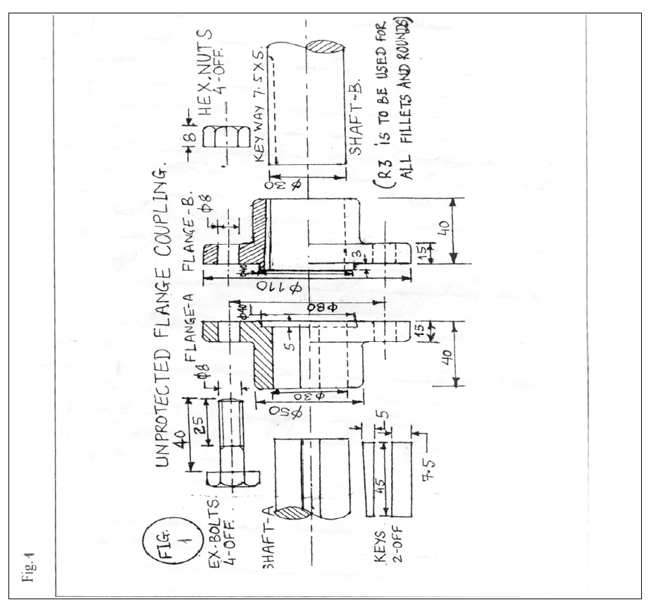
Question 3. Fig shows the details of the parts of an unprotected Flanged Coupling having rocket and spigot arrangements. Assemble these parts correctly and draw the following views to full size scale. (i) front view top half in section (ii) right hand side view. Write title & scale used. Draw projection symbol. Give seven important dimensions.
Answer: 1. Assemble the two halves of the flanged coupling (Flange A and Flange B) keyed to the two respective shafts using tapered sunk keys.
2. Engage the spigot and socket (rocket) arrangement between the two flanges to ensure precise coaxial alignment.
3. Connect the flanges securely using bolts, nuts, and washers (typically 4 or 6 bolts depending on standard sizing from the figure data).
4. Draw View (i): Front view with the top half shown in section (using \(45^\circ\) hatching lines) to reveal internal details like the shaft holes, keys, spigot-socket joint, and bolt assembly.
5. Draw View (ii): Right hand side view projected from the front view.
6. Add the title "ASSEMBLY OF UNPROTECTED FLANGED COUPLING", specify scale (1:1), draw the standard third-angle or first-angle projection symbol, and dimension seven critical parameters (such as shaft diameter, hub outer diameter, flange outer diameter, bolt circle diameter, flange thickness, etc.).
In simple words: Join the two shaft ends using two flanges fitted with keys, spigot-socket alignment, and bolts, then draw the assembled half-sectioned front view and side view.
Exam Tip: Hatching lines must be uniformly spaced at \(45^\circ\) and must never cross solid outlines. Ensure the spigot fits snugly inside the socket recess.
Free study material for Engineering Drawing
CBSE Class 12 Engineering Drawing Worksheets for All Chapters
Mastering All Chapters with Printable Worksheets
Access structured practice worksheets for All Chapters aligned with the 2026 CBSE curriculum. These downloadable exercises for Class 12 Engineering Drawing help students build accuracy and reinforce core concepts for upcoming school tests.
Verified Solutions and NCERT Alignment
Built using official NCERT guidelines for Class 12 Engineering Drawing, these practice sheets provide reliable academic support. Cross-reference your completed work with our detailed solutions to learn standard answer-writing formats for CBSE exams.
Additional Study Resources for Class 12 Engineering Drawing
Consistent engagement with these exercises builds familiarity with recurring exam themes. If specific areas within All Chapters cause trouble, utilize our dedicated NCERT solutions for Class 12 Engineering Drawing to clear up doubts immediately.
FAQs
You can download the latest chapter-wise printable worksheets for Class 12 Engineering Drawing All Chapters for free from StudiesToday.com. These have been made as per the latest CBSE curriculum for this academic year.
Yes, Class 12 Engineering Drawing worksheets for All Chapters focus on activity-based learning and also competency-style questions. This helps students to apply theoretical knowledge to practical scenarios.
Yes, we have provided solved worksheets for Class 12 Engineering Drawing All Chapters to help students verify their answers instantly.
Yes, our Class 12 Engineering Drawing test sheets are mobile-friendly PDFs and can be printed by teachers for classroom.
For All Chapters, regular practice with our worksheets will improve question-handling speed and help students understand all technical terms and diagrams.