

Advanced Study Material for Class 12 Physics: Interference of Light
Explore structured advanced study materials through the CBSE Class 12 Physics Interference of Light Theory and Examples. Tailored for Class 12 learners, utilizing these Physics resources ensures thorough preparation and strengthens foundational knowledge before final CBSE evaluations.
Practice Class 12 Physics Resources: Interference of Light
View or download the dedicated CBSE Class 12 Physics Interference of Light Theory and Examples resource below. Engaging with these advanced study guides under focused conditions ensures continuous academic progress and mastery of the 2026-27 curriculum for Interference of Light.
CBSE Class 12 Physics Interference of Light Theory and Examples. Please refer to the examination notes which you can use for preparing and revising for exams. These notes will help you to revise the concepts quickly and get good marks.
Interference of light is a key topic in the Wave Nature of Light chapter of CBSE Class 12 Physics. This notes and solved examples page covers the principle of superposition, interference of two waves, constructive and destructive interference, coherent sources, Young's double slit experiment, fringe width, Fresnel's biprism, thin films, white light fringes, and the solved examples with answers.
Topics Covered
1. Principle of superposition
2. Interference of two waves
3. Two types of interference
4. Coherent sources
5. Two methods of obtaining coherent sources
6. Conditions for sustained interference pattern
7. Young's double slit experiment
8. Fresnel's biprism experiment
9. Difference between monochromatic and white light fringes
10. To determine thickness of a thin film
11. Points to remember
1. PRINCIPLE OF SUPERPOSITION
Two or more progressive waves can travel simultaneously in a medium without affecting the motion of one another. Therefore, the resultant displacement of each particle of the medium at any instant is equal to the vector sum of the displacements produced by the two waves separately. This principle is called the principle of superposition.
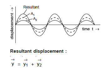
Resultant displacement: y = y1 + y2
Meaning of the principle of superposition: if a number of waves are travelling in a medium, then each one travels independently as if the other waves were not present at all. The shape and other characteristics of any wave are not changed.
2. INTERFERENCE OF TWO WAVES
When two waves of the same frequency travel in a medium simultaneously in the same direction, then, due to their superposition, the resultant intensity at any point of the medium is different from the sum of intensities of the two waves. At some points the intensity of the resultant wave is very large, while at some other points it is very small or zero. This phenomenon is called the interference of waves.
2.1 Mathematical interpretation of interference of two waves
Let two simple harmonic progressive waves of the same frequency travel in the same direction. Let a1 and a2 be the amplitudes of the waves and φ the phase difference between them at any point in the medium. If the displacements due to these waves at that point are y1 and y2, then:
y1 = a1 sin ωt ... (i)
y2 = a2 sin(ωt + φ) ... (ii)
ω/2π is the frequency of each wave. By the principle of superposition, the resultant displacement at the point is:
y = y1 + y2 = a1 sin ωt + a2 sin(ωt + φ)
= a1 sin ωt + a2 sin ωt cos φ + a2 cos ωt sin φ
= sin ωt (a1 + a2 cos φ) + cos ωt (a2 sin φ)
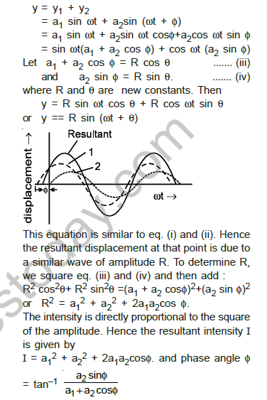
Let a1 + a2 cos φ = R cos θ ... (iii)
and a2 sin φ = R sin θ ... (iv)
where R and θ are new constants. Then:
y = R sin ωt cos θ + R cos ωt sin θ, or y = R sin(ωt + θ)
This equation is similar to equations (i) and (ii). Hence the resultant displacement at that point is due to a similar wave of amplitude R. To determine R, square equations (iii) and (iv) and then add:
R² cos² θ + R² sin² θ = (a1 + a2 cos φ)² + (a2 sin φ)²
or R² = a1² + a2² + 2a1a2 cos φ
The intensity is directly proportional to the square of the amplitude. Hence the resultant intensity I is given by:
I = a1² + a2² + 2a1a2 cos φ
The phase angle is given by:
\( \tan θ = \frac{a_2 \sin φ}{a_1 + a_2 \cos φ} \)
Thus the resultant intensity at any point depends upon the phase difference φ between the two waves at that point.
Comment: If the phase difference φ is equivalent to a path difference x or a time difference Δt, then remember:
\( \frac{φ}{2π} = \frac{x}{λ} = \frac{Δt}{T} \)
3. TWO TYPES OF INTERFERENCE
(1) Constructive interference
(2) Destructive interference
Law of conservation of energy in constructive and destructive interference: Energy is distributed non-uniformly by interference. Energy is neither produced nor destroyed. It changes from constructive to destructive and from destructive to constructive. Energy is redistributed, and it follows the law of conservation of energy.
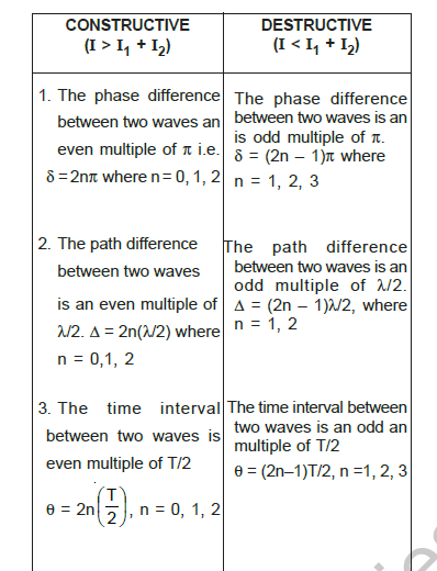
Comparative study of constructive and destructive interference
| Feature | Constructive (I > I1 + I2) | Destructive (I < I1 + I2) |
|---|---|---|
| 1. Phase difference | Even multiple of π, i.e. δ = 2nπ where n = 0, 1, 2 | Odd multiple of π, δ = (2n − 1)π where n = 1, 2, 3 |
| 2. Path difference | Even multiple of λ/2, Δ = 2n(λ/2) where n = 0, 1, 2 | Odd multiple of λ/2, Δ = (2n − 1)λ/2 where n = 1, 2 |
| 3. Time interval between two waves | Even multiple of T/2, θ = 2n(T/2) where n = 0, 1, 2 | Odd multiple of T/2, θ = (2n − 1)T/2 where n = 1, 2, 3 |
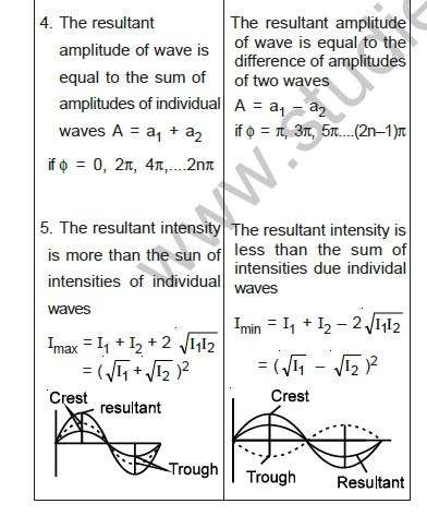
| 4. Resultant amplitude | Equal to the sum of the amplitudes of the individual waves, A = a1 + a2, if φ = 0, 2π, 4π, ..., 2nπ | Equal to the difference of the amplitudes of the two waves, A = a1 − a2, if φ = π, 3π, 5π, ..., (2n − 1)π |
| 5. Resultant intensity | More than the sum of the intensities of the individual waves, Imax = I1 + I2 + 2√(I1I2) = (√I1 + √I2)² | Less than the sum of the intensities of individual waves, Imin = I1 + I2 − 2√(I1I2) = (√I1 − √I2)² |
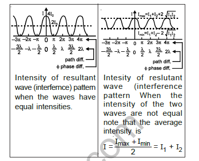
[Figure: Two graphs of intensity of the resultant wave (interference) pattern when the waves have equal intensities. The upper graph shows peaks at phase differences 0, 2π, 4π and zero at π, 3π. The lower graph shows the path difference and phase difference axes marked at π, 2π, 3π, 4π, with the constructive and destructive points labelled.]
Intensity of resultant wave (interference) pattern when the waves have equal intensities:
Intensity of resultant wave (interference pattern) when the intensities of the two waves are not equal:
Intensity when the intensities of the two waves are not equal: The average intensity is I = (Imax + Imin)/2 = I1 + I2.
4. COHERENT SOURCES
Two sources of light whose frequencies are the same, and whose phase difference between the waves emitted by them remains constant with respect to time, are defined as coherent sources.
Temporal coherence: In a typical light source (like a sodium lamp), a light wave (photon) is produced when an excited atom goes to the ground state and emits light. The duration of this is about 10⁻⁹ to 10⁻¹⁰ sec. Thus the electromagnetic (light) wave remains sinusoidal for this much time. This time is known as coherence time and is denoted by τc.
Spatial coherence: Two waves at different points in space are said to be space coherent if they preserve a constant phase difference over any time t.
[Figure: Spatial coherence diagram showing a point source S with three points P, Q and Q' marked on wavefronts at different distances from S.]
There are two independent concepts of coherence, namely (i) temporal coherence and (ii) spatial coherence.
Main points:
1. They are obtained from the same single source.
2. Their state of polarisation is the same.
Notes:
1. Laser light is highly coherent and monochromatic. Later is a source of monochromatic light waves of high degree of coherence. The entire wave front of the laser beam is spatially coherent.
2. The light emitted by two independent sources (candles, bulbs, etc.) is non-coherent, and the interference phenomenon cannot be produced by such two sources.
5. TWO METHODS OF OBTAINING COHERENT SOURCES
| S. No. | Division of Wave Front | Division of Amplitude |
|---|---|---|
| 1. | The light source is narrow. | The light source is extended. The light wave is partly reflected (50%) and partly transmitted (50%). |
| 2. | The wave front emitted by a narrow source is divided in two parts by reflection or refraction. | The amplitude of the wave emitted by an extended source of light is divided in two parts by partial reflection and partial refraction. |
| 3. | The coherent sources obtained are imaginary, e.g. Fresnel's biprism, Lloyd's mirror, Young's double slit, etc. | The coherent sources obtained are real, e.g. Newton's rings, Michelson's interferometer, colours in thin films. |
[Figure: Two diagrams. The left diagram shows a light source with a narrow slit and two coherent sources S1 and S2 that produce circular wavefronts, labelled Light source, S, S1 and S2. The right diagram shows an extended source S, a lens L, a glass plate P1 with a reflection coating, mirrors M1 and M2, and two waves labelled Two waves superpose.]
6. CONDITIONS FOR SUSTAINED INTERFERENCE PATTERN
(1) The source of light must be monochromatic.
(2) Two sources of light must be coherent.
(3) Frequencies of the two waves must be the same.
(4) The amplitudes of the two waves must be nearly equal.
(5) The distance between the two light sources must be small.
(6) The two coherent sources must be narrow.
(7) If the two light waves are polarised, then their state of polarisation must be the same.
(8) The two light waves must travel in the same direction.
(9) The vibrations of the two waves must be in the same direction.
(10) The distance between the source and the screen must be large.
7. EXPERIMENT OF YOUNG'S DOUBLE SLIT
(1) This experiment is performed to show the practical form of interference of light.
(2) The slits S1 and S2 behave as two coherent sources.
(3) On the screen, bright and dark portions are alternately found.
(4) The bright portion is called a bright fringe and the dark portion is called a dark fringe.
(5) The central fringe is always bright.
(6) Energy is conserved in the interference of light.
(7) It is explained on the basis of Huygens' principle.
(8) This experiment verifies the wave nature of light.
[Figure: Young's double slit arrangement. A light source S illuminates two slits S1 and S2 placed at a distance d apart. The screen is at distance D. The resulting interference fringes are shown with the labels: Second bright, Second dark, First bright, First dark, Central bright, First dark, First bright, Second dark, Second bright. The geometry of the path from S1 and S2 to a point P on the screen, with the point O at the centre and distance x from O, is also shown.]
(a) At a point on the screen, to find a dark or bright fringe, it depends upon the path difference between the S1P and S2P light waves.
(b) There are two types of path difference between light waves: (i) geometrical path difference and (ii) optical path difference.
(c) In the above experiment, the optical path difference = 0, and S1P and S2P have a geometrical path difference. So the total path difference = geometrical difference S2P − S1P = xd/D
(note: sin θ ≈ tan θ ≈ θ)
Waves at P are y1 = a0 sin ωt and y2 = a0 sin(ωt + φ), where
\( φ = \frac{2π}{λ} (S_2P − S_1P) \)
The amplitude of the resultant wave at P is a = 2a0 cos(φ/2), and the intensity of the resultant wave at point P is:
I = 4I0 cos²(φ/2)
Bright fringes: If the nth bright fringe forms at point P, then for a bright fringe:
S2P − S1P = \( \frac{x_n d}{D} \) = nλ, so \( x_n = \frac{nλD}{d} \)
Distance between the central fringe and the nth bright fringe:
\( x_n = \frac{nλD}{d} \)
n = 1 gives the first bright fringe, n = 2 gives the second bright fringe.
Dark fringes: If the nth dark fringe forms at a point P, then for a dark fringe:
\( \frac{x_n d}{D} = \frac{(2n − 1)λ}{2} \)
Distance between the central fringe and the nth dark fringe:
\( x_n = \frac{(2n − 1)λD}{2d} \)
n = 1 gives the first dark fringe, n = 2 gives the second dark fringe.
Fringe width: The distance between a dark fringe and a bright fringe which are in coming order is called fringe width. The fringe width of dark and bright fringes is the same:
\( β = \frac{λD}{d} \)
Angular width of fringe: The angular width of the fringe is α = β/D, and α = λ/d (in radian). Also α D = β.
[Figure: Angular width of fringe. Two slits S1 and S2 at the left, with an angle α shown between the line from the slits to the centre of the screen. Fringe width β is marked on the screen at the right, and the distance D is marked between the slits and the screen.]
Comments on Young's interference experiment:
(i) Energy is conserved in interference. This indicates that energy is redistributed from the destructive interference region to the constructive interference region.
(ii) If the entire arrangement of Young's double slit experiment is immersed in water, then the fringe width decreases. \( \frac{β_{water}}{β_{air}} = \frac{λ_{water}}{λ_{air}} = \frac{1}{a μ_w} = \frac{1}{(4/3)} \) .
(iii) If white light is used in place of monochromatic light in Young's double slit experiment:
(a) The central fringe is white.
(b) Coloured fringes appear around the central white fringe.
(c) The inner edge of the dark fringe is red, and the outer edge is violet (or blue).
(d) The inner edge of the bright fringe is violet (or blue), and the outer edge is red.
(iv) If a filter allowing only λred (or λ1) is placed in front of slit S1, and a filter allowing only λblue (or λ2) is placed in front of slit S2, then there does not occur any interference (refer to point 3 of the conditions).
(v) If a thin glass plate or mica sheet is placed in front of one of the slits, the central fringe shifts towards the slit in front of which the glass plate is placed. If t is the thickness of the glass or mica sheet and μ is the refractive index, then the optical path = μt, so the extra path difference = (μ − 1)t. If the central fringe now appears at the location of the previously formed nth bright fringe, then (μ − 1)t = nλ. If the central fringe appears at the position of the previously formed nth dark fringe, then (μ − 1)t = (2n − 1)λ/2.
(vi) If the width of the slit S is increased, the degree of spatial coherence decreases. As a result, the interference pattern gradually disappears. A similar effect occurs if d between S1 and S2 is increased.
(vii) The fringe visibility is:
\( V = \frac{I_{max} − I_{min}}{I_{max} + I_{min}} \)
V is maximum if I1 = I2 = I0 or Imin = 0. If the widths of slits S1 and S2 are unequal, the brightness of the bright fringe and the darkness of the dark fringe decrease. If I1 >> I2, then Imax ≈ Imin.
(viii) When waves from two coherent sources S1 and S2 interfere in space, the shape of the fringe is hyperbolic, with foci at S1 and S2.
8. FRESNEL'S BIPRISM EXPERIMENT
(1) It is an optical device to obtain two coherent sources by refraction of light. With the help of this experiment, the wavelength of monochromatic light, the thickness of thin films and their refractive index, and the distance between apparent coherent sources can be determined.
(2) The angle of the biprism is 179° and the refracting angle is α = 1/2°.
(3) Distance between source and screen D = a + b. Distance between the two coherent sources:
d = 2a(μ − 1)α
where a = distance between source and biprism, b = distance between screen and biprism, α = refracting angle of biprism, and μ = refractive index of the material of the prism.
Fringe width:
\( λ = \frac{dβ}{D} = \frac{2a(μ − 1)αβ}{(a + b)} \)
Here α in radian = α° × \( \frac{314}{180} \) radian (using π = 3.14).
Note: If the refracting angle and refractive index are not known, then d can be calculated by using a convex lens. One convex lens is taken which has focal length f such that 4f < D. The convex lens is first kept near the biprism and d1 is calculated. Then it is kept near the eyepiece and d2 is calculated. Then:
\( d = \sqrt{d_1 d_2} \)
Also \( λ = \frac{\sqrt{d_1 d_2}\, β}{(a + b)} \)
Application: The apparatus can be used to find the wavelength of monochromatic light, the thickness of thin films, their refractive index, and the distance between apparent coherent sources.
Fringe width when Fresnel's arrangement is immersed in water:
(1) Effect on d: dwater < dair. Thus, when Fresnel's biprism experiment is immersed in water, the separation between the two virtual sources decreases, but in Young's double slit experiment it does not change.
(2) Effect on β: The fringe width increases in both Fresnel's biprism and Young's double slit experiment.
[Figure: Fresnel's biprism diagram. A source S with two virtual sources S1 and S2 on either side of the biprism, shown with the angle α and the apex A. Distances a (source to biprism) and b (biprism to screen) and total distance D are marked. The fringe pattern on the screen is shown as a striped band labelled Fringe Pattern, and the screen is labelled Screen with the points P and Q. Below it is the lens arrangement with lenses L1 and L2, the images S1, S2, S1', S2', S1'' and S2'' and the separations d1 and d2 marked.]
9. DIFFERENCE BETWEEN MONOCHROMATIC LIGHT FRINGES AND WHITE LIGHT FRINGES
| S. No. | Monochromatic Light Fringes | White Light Fringes |
|---|---|---|
| 1. | Central fringe is always bright. | Central fringe is always white. |
| 2. | The width of all fringes is the same. | The fringe width of different colours is different. |
| 3. | Fringes of higher order are also obtained. | In the region of fringes of higher order, uniform illumination is obtained. |
| 4. | The number of fringes obtained is more. | The number of fringes obtained is less. |
| 5. | There are alternate bright and dark fringes on both sides of the central fringe. | When the path difference is small, some coloured fringes are obtained on both sides of the central fringe. |
[Figure: Two diagrams. The left one shows a monochromatic source of light S with slits S1 and S2 and a screen with points P, O and P', labelled Bright or dark fringe and Bright fringe. The right one shows a white source of light S with slits S1 and S2 and a screen with points P, O and P', labelled Achromatic fringe and Coloured fringe.]
10. TO DETERMINE THICKNESS OF A THIN FILM
On placing the film, the whole interference pattern gets shifted on the side where the film is placed. When a thin film of thickness t and refractive index μ is placed in the path of one of the waves, the fringe pattern gets shifted by a distance x. The path difference increases by (μ − 1)t on placing the plate. If the shift is equivalent to n fringes, then:
\( n = \frac{(μ − 1)t}{λ} \) and \( x = \frac{(μ − 1)tD}{d} \)
11. POINTS TO REMEMBER
(1) The fringe width increases with increase of distance between the source and the screen.
(2) Fringe width decreases by increasing the distance between the two slits S1 and S2.
(3) If the experiment is repeated in water instead of air, then λ decreases and consequently β decreases.
(4) When one of the slits S1 or S2 is closed, interference does not take place.
(5) When the two slits are illuminated by two independent sources, then interference fringes are not obtained.
(6) When one of the slits is closed and the width of another is made of the order of λ, then diffraction fringes are observed.
(7) When the slit is illuminated with different colours, then fringes are obtained of the same colour, but their fringe widths are different.
(8) When the interference experiment is repeated in a denser medium, both λ and β decrease.
(9) In Young's double slit experiment, light waves undergo diffraction at both the slits, and the diffracted waves superimpose to produce interference.
(10) The colours obtained in thin films are due to interference, whereas those obtained in a prism are due to dispersion.
(11) If the biprism experiment is repeated in a liquid instead of air, then the fringe width increases (whereas in Young's double slit experiment it decreases).
(12) The colours obtained in thin films are due to interference, whereas those obtained in a prism are due to dispersion.
(13) The wavelength undergoing destructive interference will be absent.
(14) The wavelength for which the condition of constructive interference is fulfilled will be visible maximum, and consequently the fringes will be coloured.
SOLVED EXAMPLES
Examples based on Intensity of interference pattern
Ex.1 The two coherent sources of intensity ratio 2 : 8 produce an interference pattern. The values of maximum and minimum intensities will be respectively
(A) I1 and 9I1
(B) 9I1 and I1
(C) 2I1 and 8I1
(D) 8I1 and 2I1
Answer: (B) 9I1 and I1
1. Where I1 is the intensity of the first source, Imax = I1 + I2 + 2√(I1I2)
2. According to the question, I1/I2 = 2/8 = 1/4, so I2 = 4I1
3. Imax = I1 + 4I1 + 2√(4I1²) = 5I1 + 4I1 = 9I1
4. Imin = I1 + I2 − 2√(I1I2) = I1 + 4I1 − 4I1 = I1
5. Hence the correct answer is (B).
Teacher's Note:
a) Use the 2√(I1I2) term with a plus sign for the maximum and a minus sign for the minimum.
b) Intensity ratio 2 : 8 gives I2 = 4I1, which is the step that most students skip.
c) Check that Imax + Imin = 10I1 = 2(I1 + I2).
Ex.2 In Young's double slit experiment, the distance between two slits is made three times, then the fringe width will become -
(A) 9 times
(B) 1/9 times
(C) 3 times
(D) 1/3 times
Answer: (D) 1/3 times
1. Fringe width β = λD/d, so β ∝ 1/d
2. On increasing d three times, β becomes \( \frac{1}{3} \) times.
3. Hence the correct answer is (D).
Teacher's Note:
a) Fringe width is inversely proportional to the slit separation.
b) Tripling d reduces β to one third, not to one ninth.
Ex.3 In Young's double slit experiment, the fringe width distant screen is 1°. If the wave length of light is 6000Å then the distance between two slits will be
(A) 0.34mm
(B) .034m
(C) 34mm
(D) 340
Answer: The correct value is d = 0.034 mm (about 3.4 × 10⁻⁵ m).
1. Angular fringe width α = 1° = \( \frac{π}{180} \) radian
2. Angular width α = λ/d, so d = λ/α
3. λ = 6 × 10⁻⁷ m
4. d = \( \frac{6 × 10^{-7} × 180}{3.14} \) m = 3.44 × 10⁻⁵ m = 0.034 mm
Teacher's Note:
a) The printed option (B) .034m has the right digits but the wrong unit, since the value is 0.034 mm, which is 3.4 × 10⁻⁵ m.
b) The printed options (A) 0.34 mm and (C) 34 mm are off by a factor of ten and a thousand respectively.
c) Keep the value of π as 3.14 as given in the solution, and convert the angle to radians first.
Ex.4 In Young's double slit experiment 10th order maximum is obtained at the point of observation in the interference pattern for λ = 7000 Å. If the source is replaced by another one of wavelength 5000 Å then the order of maximum at the same point will be -
(A) 12 th
(B) 14 th
(C) 16 th
(D) 18 th
Answer: (B) 14 th
1. The same point is a maximum for both wavelengths, so n1λ1 = n2λ2
2. 10 × 7000 = n2 × 5000
3. n2 = 14
4. Hence the correct answer is (B).
Teacher's Note:
a) A higher order is obtained for the shorter wavelength at the same point.
b) Multiply the order by its wavelength to get the path difference at that point.
Ex.5 In Young's double slit experiment the two slits are illuminated by light of wavelength 5890 Å and the distance between the fringes obtained on the screen is 0.2°. If the whole apparatus is immersed in water then the angular fringe width will be, if the refractive index of water is 4/3
(A) 0.30°
(B) 0.15°
(C) 15°
(D) 30°
Answer: (B) 0.15°
1. Angular fringe width ωa = λ/d, so ωa ∝ λ
2. \( \frac{(ω_a)_{water}}{ω_a} = \frac{λ_{water}}{λ} = \frac{1}{μ_{water}} \)
3. (ωa)water = \( \frac{0.2}{4/3} \) = 0.15°
4. Hence the correct answer is (B).
Teacher's Note:
a) Angular fringe width is directly proportional to the wavelength.
b) Dividing by the refractive index of water reduces the angular width.
Ex.6 The intensities of two light sources are I and 9I respectively. If the phase difference between the waves emitted by them is π then the resultant intensity at the point of observation will be -
(A) 3I
(B) 4I
(C) 10I
(D) 82I
Answer: (B) 4I
1. I' = I1 + I2 + 2√(I1I2) cos φ
2. I1 = I, I2 = 9I, φ = π
3. I' = I + 9I + 2√(9I²) cos π = 10I − 6I
4. I' = 4I
Teacher's Note:
a) A phase difference of π gives cos π = −1, so the term is subtracted.
b) The square root of 9I² is 3I, not 9I.
c) Result check: 4I lies between I_min and I_max, as the formula requires.
Examples based on Fresnel's biprism experiment
Ex.7 In Fresnel's biprism experiment the width of 10 fringes is 2cm which are formed at a distance of two 2 meter from the slit. If the wavelength of light is 5100Å then the distance between two coherent sources will be
(A) 5.1 × 10⁻⁴ m.
(B) 5.1 × 10⁴ cm.
(C) 5.1 × 10⁻⁴ mm
(D) 10.1 × 10⁻⁴ cm
Answer: (A) 5.1 × 10⁻⁴ m.
1. Fringe width β = \( \frac{2 × 10⁻²}{10} \) m = 2 × 10⁻³ m
2. D = 2 m and λ = 5100 × 10⁻¹⁰ m = 5.1 × 10⁻⁷ m
3. d = \( \frac{Dλ}{β} \) = \( \frac{2 × 5.1 × 10^{-7}}{2 × 10^{-3}} \) = 5.1 × 10⁻⁴ m
Teacher's Note:
a) The width of 10 fringes is 2 cm, so one fringe width is 2 mm.
b) Convert the wavelength from Å to metres before substituting.
c) The final answer is 5.1 × 10⁻⁴ m, which is 0.51 mm.
Ex.8 Two coherent sources of intensity ratio 1 : 4 produce an interference pattern. The fringe visibility will be
(A) 1
(B) 0.8
(C) 0.4
(D) 0.6
Answer: (B) 0.8
1. V = \( \frac{I_{max} − I_{min}}{I_{max} + I_{min}} \)
2. \( \frac{I_{max}}{I_{min}} = \frac{\left(\sqrt{I_1} + \sqrt{I_2}\right)^2}{\left(\sqrt{I_1} − \sqrt{I_2}\right)^2} \)
3. I1/I2 = 1/4, so √(I1/I2) = 1/2
4. \( \frac{I_{max}}{I_{min}} = \frac{(1/2 + 1)^2}{(1/2 − 1)^2} = \frac{9/4}{1/4} = 9 \)
5. V = \( \frac{9 − 1}{9 + 1} \) = \( \frac{8}{10} \) = 0.8
6. Hence the correct answer is (B).
Teacher's Note:
a) Visibility uses the ratio of the maximum to the minimum intensity.
b) Use the square roots of the intensities, not the intensities themselves, in the ratio.
c) Visibility always lies between 0 and 1.
Ex.9 When a mica sheet (μ = 1.6) of thickness 7 microns is placed in the path of one of interfering beams in the biprism experiment then the central fringe gets shifted at the position of seventh bright fringe. The wavelength of light used will be -
(A) 4000Å
(B) 5000Å
(C) 6000 Å
(D) 7000Å
Answer: (C) 6000 Å
1. For the central fringe to shift to the nth bright fringe, (μ − 1)t = nλ
2. λ = \( \frac{(μ − 1)t}{n} \) = \( \frac{(1.6 − 1) × 7 × 10^{-6}}{7} \)
3. λ = 6 × 10⁻⁷ m = 6000 Å
4. Hence the correct answer is (C).
Teacher's Note:
a) The shift equals the path difference (μ − 1)t, measured in wavelengths.
b) Here the 7 microns cancels against the 7 bright fringes, which keeps the arithmetic short.
Ex.10 In Fresnel's biprism experiment the width of 10 fringes is 2 cm which are formed at a distance of two 2 meter from the slit. If the wavelength of light is 5100Å then the distance between two coherent sources will be -
(A) 5.1 × 10⁻⁴ m
(B) 5.1 × 10⁻⁴ cm
(C) 5.1 × 10⁻⁴ mm
(D) 10.1 × 10⁻⁴ m
Answer: (A) 5.1 × 10⁻⁴ m
1. β = 2 cm / 10 = 2 × 10⁻³ m
2. d = \( \frac{Dλ}{β} \) = \( \frac{2 × 5.1 × 10^{-7}}{2 × 10^{-3}} \) = 5.1 × 10⁻⁴ m
3. Hence the correct answer is (A).
Teacher's Note:
a) This is the same set of data as Ex.7, with a different list of options.
b) Option (B) has the same digits but the unit cm, which is wrong for this distance.
Ex.11 In Fresnel's biprism experiment of distance of mth bright fringe from zeroth order fringe will be -
(A) (2m − 1) \( \frac{λD}{2d} \)
(B) \( \frac{mDλ}{d} \)
(C) \( \frac{md}{λD} \)
(D) (2m + 1) \( \frac{λD}{2d} \)
Answer: (B) \( \frac{mDλ}{d} \)
1. The distance of the mth bright fringe from the central fringe is Xm = \( \frac{mλD}{d} \)
2. This equals \( \frac{mDλ}{d} \), which is option (B).
Teacher's Note:
a) The bright fringe distance is a whole multiple of the fringe width.
b) Dark fringe distances carry the (2n − 1)/2 factor, so do not mix the two formulas.
c) Option (D) is a dark-fringe type expression, not a bright-fringe one.
Ex.12 When a plastic thin film of refractive index 1.45 is placed in the path of one of the interfering waves then the central fringe is displaced through width of five fringes. The thickness of the film will be, if the wavelength of light is 5890 Å -
(A) 6.544 × 10⁻⁴ cm
(B) 6.544 × 10⁻⁴ m
(C) 6.54 × 10⁻⁴ cm
(D) 6.5 × 10⁻⁴ cm
Answer: (A) 6.544 × 10⁻⁴ cm
1. Shift x0 = 5β, and x0 = \( \frac{β}{λ} \)(μ − 1)t
2. So \( 5β = \frac{β (0.45) t}{λ} \), which gives t = \( \frac{5λ}{0.45} \)
3. t = \( \frac{5 × 5890 × 10^{-10}}{0.45} \) m = 6.544 × 10⁻⁶ m
4. t = 6.544 × 10⁻⁴ cm
Teacher's Note:
a) Here μ − 1 = 0.45, which is the value to use, not 1.45.
b) Metres and centimetres differ by a factor of 100, so 6.544 × 10⁻⁶ m equals 6.544 × 10⁻⁴ cm.
c) The option with the wrong power of ten is the usual trap.
Ex.13 When a mica sheet of thickness 7 microns is placed in the path of one of interfering beams in the biprism experiment then the central fringe gets shifted at the position of seventh bright fringe. The wavelength of light used will be .
(A) 4000Å
(B) 5000Å
(C) 6000Å
(D) 7000Å
Answer: (C) 6000Å
1. λ = \( \frac{(μ − 1)t}{n} \)
2. With n = 7, μ = 1.6 and t = 7 × 10⁻⁶ m
3. λ = 6 × 10⁻⁷ m = 6000 Å
4. Hence the correct answer is (C).
Teacher's Note:
a) This question repeats Ex.9 with the same data.
b) The refractive index of the mica sheet is 1.6, so μ − 1 is 0.6.

Free study material for Physics
Free CBSE Study Guides: Class 12 Physics Interference of Light
Essential Notes for Class 12 Physics
Access comprehensive study material for Interference of Light, including revision notes, concept maps, and high-probability questions. These resources are designed in alignment with the latest 2026 CBSE syllabus for Class 12 Physics to support effective exam preparation.
Verified Solutions for Class 12 Physics
Each resource draws directly from authorized textbooks to maintain academic accuracy. Evaluating solved examples allows Class 12 students to master the formal presentation and answer-writing standards expected in upcoming school exams.
Enhance Accuracy with Online Tests
Maximize your grade potential by utilizing Class 12 Physics practice papers in tandem with these structured notes. All printable assignments and interactive mock tests on our platform are updated for the 2026 session and available free of charge.
FAQs
Our advanced study package for Interference of Light includes detailed concepts, diagrams, Mind Maps, and explanation of complex topics to ensure Class 12 students learn as per syllabus for 2026 exams.
The Mind Maps provided for Interference of Light act as visual anchors which will help faster recall during high-pressure exams.
Yes, teachers use our Class 12 Physics resources for lesson planning as they are in simple language and have lot of solved examples.
Yes, You can download the complete, mobile-friendly PDF of the Physics Interference of Light advanced resources for free.
Yes, our subject matter experts have updated the Interference of Light material to align with the rationalized NCERT textbooks and have removed deleted topics and added new competency-based questions.