

Class 12 Physics Study Guide: CBSE Class 12 Physics Capacitance Solved Examples
Access comprehensive study materials and useful resources for Capacitance using the CBSE Class 12 Physics Capacitance Solved Examples. Designed to align with the 2026-27 CBSE academic guidelines, these advanced resources help Class 12 Physics students reinforce core concepts beyond standard textbooks.
Download Capacitance Study Material PDF
Navigate directly to the advanced Physics study materials using the digital viewer below. Each resource pack includes detailed conceptual summaries and solved practice questions, allowing students to instantly reinforce their learning.
This Class 12 Physics page gives solved examples on Capacitance: series and parallel combinations of capacitors, energy stored, redistribution of charge, dielectric slabs, parallel plate capacitors and the point potential method for complicated networks, each with a worked solution.
SOLVED EXAMPLES
Ex. 1 The capacitor of capacitance 4μF and 6μF are connected in series. A potential difference of 500 volts is applied to the outer plates of the two capacitor system. Then the charge on each capacitor is numerically-
(A) 6000 C
(B) 1200C
(C) 1200 μC
(D) 6000μC
Answer: (C) 1200 μC
1. Equivalent capacitance CR = \( \frac{C_1 C_2}{C_1 + C_2} \) = \( \frac{4 \times 6}{4 + 6} \) = 2.4 μF
2. In a series combination the charge on each capacitor equals the charge flowing through the circuit.
3. Charge = CR V = 2.4 × 10⁻⁶ × 500 = 1200 × 10⁻⁶ C = 1200 μC
4. Hence, the correct option is (C).
Teacher's Note:
a) Capacitors in series carry the same charge; the voltage divides between them.
b) Check the unit: 10⁻⁶ C is 1 μC, so 1200 μC and not 1200 C.
Ex. 2 Three capacitors are connected to D.C. source of 100 volts as shown in the adjoining figure. If the charge accumulated on plates of C1, C2 and C3 are qa, qb, qc, qd, qe and qf respectively, then
(A) qb + qd + qf = \( \frac{100}{2} \) C
(B) qb + qd + qf = 0
(C) qa + qc + qe = 50 C
(D) qb = qd = qf

[Figure: Three capacitors in series with a 100 volt battery: C1 = 2μF (plates a, b), C2 = 3μF (plates c, d) and C3 = 4μF (plates e, f), connected in a single loop with the 100 volt battery at the bottom]
Answer: (D) qb = qd = qf
1. The three capacitors are in series, so each carries the same magnitude of charge q.
2. Plate a carries +q, plate b carries -q, plate c carries +q, plate d carries -q, plate e carries +q and plate f carries -q, because the plates b and c, and the plates d and e, are joined by wires and together stay neutral.
3. So qb = qd = qf = -q.
4. The sums in options (A), (B) and (C) are -3q, -3q and +3q, which are not the values given there.
5. Hence, the correct option is (D).
Teacher's Note:
a) Series capacitors share one charge value; look at the sign of each plate, not just the size.
b) Joined plates such as b and c have equal and opposite charges, since the pair is neutral.
Ex. 3 Three capacitors each of capacitance 1μF are connected in parallel. To this combination, a fourth capacitor of capacitance 1μF is connected in series. The resultant capacitance of the system is-
(A) 4μF
(B) 2μF
(C) 4/3 μF
(D) 3/4 μF
Answer: (D) 3/4 μF
1. The three capacitors in parallel give C' = 1 + 1 + 1 = 3 μF.
2. This is in series with the fourth capacitor: \( \frac{1}{C_r} \) = \( \frac{1}{3} \) + \( \frac{1}{1} \) = \( \frac{4}{3} \)
3. Cr = \( \frac{3}{4} \) μF
4. Hence, the correct option is (D).
Teacher's Note:
a) Add capacitances in parallel; add reciprocals in series.
b) The answer must be less than 1 μF because a series connection always gives less than the smallest capacitor.
Ex. 4 In the circuit diagram shown in the adjoing figure, the resultant capacitance between P and Q is-
(A) 47 μF
(B) 3μF
(C) 60 μF
(D) 10 μF

[Figure: A 3μF and a 2μF capacitor in parallel on the left side, a 12μF capacitor along the top wire, a 20μF capacitor along the bottom wire, with terminals P and Q on the right; 1500V is marked beside the terminals]
Answer: (B) 3μF
1. The 3 μF and 2 μF capacitors are in parallel: C = 3 + 2 = 5 μF.
2. This 5 μF capacitor, the 20 μF capacitor and the 12 μF capacitor are in series between P and Q.
3. 1/CPQ = \( \frac{1}{5} \) + \( \frac{1}{20} \) + \( \frac{1}{12} \) = \( \frac{20}{60} \) = \( \frac{1}{3} \)
4. CPQ = 3 μF
5. Hence, the correct option is (B).
Teacher's Note:
a) First reduce the parallel pair, then treat the rest as one series chain.
Ex. 5 Four condensers each capacity 4μF are connected as shown in figure VP - VQ = 15 volts. The energy stored in the system is-
(A) 2400 ergs
(B) 1800ergs
(C) 3600 ergs
(D) 5400 ergs
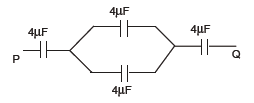
[Figure: From terminal P: a 4μF capacitor in series, then two 4μF capacitors in parallel (one upper, one lower branch), then another 4μF capacitor in series, ending at terminal Q]
Answer: (B) 1800ergs
1. The two middle 4 μF capacitors are in parallel: C = 4 + 4 = 8 μF.
2. This 8 μF is in series with the two end capacitors of 4 μF each: \( \frac{1}{C_R} \) = \( \frac{1}{4} \) + \( \frac{1}{8} \) + \( \frac{1}{4} \) = \( \frac{5}{8} \)
3. CR = \( \frac{8}{5} \) μF
4. Energy stored = \( \frac{1}{2} \) CRV² = \( \frac{1}{2} \) × \( \frac{8}{5} \) × 10⁻⁶ × 225 = 180 × 10⁻⁶ J
5. 1 J = 10⁷ ergs, so energy = 180 × 10⁻⁶ × 10⁷ = 1800 ergs
6. Hence, the correct option is (B).
Teacher's Note:
a) 1 joule equals 10⁷ erg; convert at the end.
b) The energy formula ½CV² uses the total voltage across the whole combination.
Ex. 6 Two capacitors each of 0.5 μF capacitance are connected in parallel and are then charged by 200 volts. D.C. supply. The total energy of their charges (in joules) is-
(A) 0.01
(B) 0.02
(C) 0.04
(D) 0.06

Answer: (B) 0.02
1. In parallel CR = 0.5 + 0.5 = 1 μF.
2. E = \( \frac{1}{2} \) CRV² = \( \frac{1}{2} \) × 1 × 10⁻⁶ × 200 × 200
3. E = 2 × 10⁻² J = 0.02 J
4. Hence, the correct option is (B).
Teacher's Note:
a) Parallel capacitors have the same voltage, so total energy is ½(C1 + C2)V².
Ex. 7 An infinite number of identical capacitors each of capacitance 1μF are connected as in adjoining figure. Then the equivalent capacitance between A and B is-
(A) 1 μF
(B) 2μF
(C) 1/2 μF
(D) ∞
[Figure: Between terminals A and B, vertical wires on the left and right join rows of 1μF capacitors in parallel: the first row has 1 capacitor, the second row 2 capacitors in series, the third row 4, the fourth row 8 (marked 8 cap.), the fifth row 16 (marked 16 cap.), and the rows continue to infinity]
Answer: (B) 2μF
1. Each row is a string of identical 1 μF capacitors in series, and all rows are in parallel between A and B.
2. The rows contain 1, 2, 4, 8, 16, ... capacitors, so their capacitances are 1, 1/2, 1/4, 1/8, 1/16, ... μF.
3. Total C = 1 + \( \frac{1}{2} \) + \( \frac{1}{4} \) + \( \frac{1}{8} \) + ... which is a G.P. with first term a = 1 and common ratio r = \( \frac{1}{2} \)
4. Sum of an infinite G.P. S = \( \frac{a}{1 - r} \) = \( \frac{1}{1 - 1/2} \) = 2
5. So CR = 2 μF.
6. Hence, the correct option is (B).
Teacher's Note:
a) A row of n identical capacitors in series has capacitance C/n.
b) The infinite G.P. sum works only because |r| is less than 1.
Ex. 8 Four capacitors are connected as shown in the adjoining figure. The potential difference between A and B is 1500 volts. The energy stored in 2μF capacitance will be-
(A) 5.06J
(B) 0.506J
(C) 50.6J
(D) none of the above.
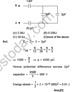
[Figure: Terminal B connects through a 12μF capacitor to the top wire; terminal A connects through a 20μF capacitor to the bottom wire; between the top and bottom wires on the right a 2μF capacitor and a 3μF capacitor are connected side by side in parallel]
Answer: (D) none of the above.
1. The 2 μF and 3 μF capacitors are in parallel: C = 2 + 3 = 5 μF.
2. This 5 μF, the 12 μF and the 20 μF capacitors are in series, so 1/CAB = \( \frac{1}{12} \) + \( \frac{1}{20} \) + \( \frac{1}{5} \) = \( \frac{20}{60} \), giving CAB = 3 μF.
3. Charge q = CAB VAB = 3 × 1500 = 4500 μC
4. Potential difference across the 2 μF capacitor = \( \frac{4500}{5} \) = 900 V
5. Energy stored in 2 μF = \( \frac{1}{2} \) × 2 × 10⁻⁶ × (900)² = 0.81 J
6. 0.81 J matches none of 5.06 J, 0.506 J or 50.6 J.
7. Hence, the correct option is (D).
Teacher's Note:
a) The charge on the series chain splits into the parallel capacitors only by their voltage, not equally.
b) The energy formula is ½CV² for the single capacitor being asked about.
Ex. 9 Four capacitors of each capacity 3μF are connected as shown in the adjoining figure. The ratio of equivalent capacitance between A and B and between A and C will be-
(A) 4 : 3
(B) 3 : 4
(C) 2 : 3
(D) 3 : 2
[Figure: A square loop of four 3μF capacitors, one on each side; terminal A is at the top left corner, terminal B at the top right corner and terminal C at the bottom right corner]
Answer: (A) 4 : 3
1. Between A and B: the direct 3 μF capacitor is in parallel with the other three 3 μF capacitors in series, which give \( \frac{3}{3} \) = 1 μF.
2. CAB = 3 + 1 = 4 μF
3. Between A and C: the left and bottom capacitors in series give \( \frac{3}{2} \) μF, and the top and right capacitors in series also give \( \frac{3}{2} \) μF; these two paths are in parallel.
4. CAC = \( \frac{3}{2} \) + \( \frac{3}{2} \) = 3 μF
5. CAB : CAC = 4 : 3
6. Hence, the correct option is (A).
Teacher's Note:
a) Redraw the loop for each pair of terminals; the same square gives different answers.
b) The ratio is asked as AB to AC, not the reverse.
Ex. 10 A capacitor of capacity C1 is charged to the potential of V0. On disconnecting with the battery, it is connected with a capacitor of capacity C2 as shown in the adjoining figure. The ratio of energies before after the connection of switch S will be-
(A) (C1 + C2)/C1
(B) C1 / (C1 + C2)
(C) C1C2
(D) C1/C2
[Figure: Capacitor C1 carrying potential V0 on the left and capacitor C2 on the right, joined by wires with a switch S in the top wire]
Answer: (A) (C1 + C2)/C1
1. Energy = \( \frac{q^2}{2C} \)
2. The charge q stays the same when the switch is closed, and the capacitors join in parallel, so Cafter = C1 + C2.
3. Ebefore / Eafter = \( \frac{q^2 / 2C_1}{q^2 / [2(C_1 + C_2)]} \) = \( \frac{C_1 + C_2}{C_1} \)
4. Hence, the correct option is (A).
Teacher's Note:
a) The ratio is greater than 1, because some energy is lost when charge flows between the capacitors.
b) Use E = q²/2C when the charge is the quantity that stays constant.
Ex. 11 Four plates of the same area of cross-section are joined as shown in the figure. The distance between each plate is d. The equivalent capacity across AB will be-
(A) \( \frac{2\varepsilon_0 A}{d} \)
(B) \( \frac{3\varepsilon_0 A}{d} \)
(C) \( \frac{3\varepsilon_0 A}{2d} \)
(D) \( \frac{\varepsilon_0 A}{d} \)
[Figure: Four parallel plates of equal area, each at distance d from the next; terminal A is joined to the first and third plates, and terminal B is joined to the second and fourth plates]
Answer: (B) \( \frac{3\varepsilon_0 A}{d} \)
1. The four plates are joined alternately, so plates 1 and 3 go to one terminal and plates 2 and 4 go to the other.
2. This gives three capacitors, between plates 1-2, 2-3 and 3-4, each of capacitance \( \frac{\varepsilon_0 A}{d} \) and all in parallel.
3. C = \( \frac{\varepsilon_0 A}{d} \) + \( \frac{\varepsilon_0 A}{d} \) + \( \frac{\varepsilon_0 A}{d} \) = \( \frac{3\varepsilon_0 A}{d} \)
4. Hence, the correct option is (B).
Teacher's Note:
a) n plates joined alternately give (n - 1) capacitors in parallel.
b) Count the gaps between plates, not the plates.
Ex. 12 The capacity of the capacitors are shown in the adjoining fig. The equivalent capacitance between the points A and B and the charge on the 6μF capacitor will be-
(A) 27μF, 540μC
(B) 15μF, 270μC
(C) 6μF, 180 μC
(D) 15μF, 90μC
[Figure: A 90 volt battery between terminals A and B. From B, a 9μF capacitor in series, then a junction C. The 6μF and 12μF capacitors are connected in parallel between that junction and terminal A]
Answer: (C) 6μF, 180 μC
1. The 6 μF and 12 μF capacitors are in parallel: C = 6 + 12 = 18 μF.
2. This 18 μF is in series with the 9 μF capacitor: Ceq = \( \frac{9 \times 18}{9 + 18} \) = 6 μF
3. Total charge q = 6 × 90 = 540 μC, and the same charge is on the 9 μF and on the 18 μF combination.
4. Voltage across the 18 μF combination = \( \frac{540}{18} \) = 30 V, so VAC = 30 V.
5. Charge on the 6 μF capacitor = 30 × 6 = 180 μC
6. Hence, the correct option is (C).
Teacher's Note:
a) In a series chain the voltage divides inversely as the capacitance; here 90 V splits as 60 V on 9 μF and 30 V on 18 μF.
b) After finding the parallel voltage, find each branch charge from q = CV.
Ex. 13 In the connection shown in the adjoining figure. the equivalent capacity between A and B will be-
(A) 8μF
(B) 12μF
(C) 20μF
(D) 2 μF
[Figure: Terminal A on the left, terminal B on the right. A 9μF capacitor and a 24μF capacitor are in series along the middle wire from A, followed by a 12μF capacitor reaching B. A 6μF capacitor on a top wire joins A to the point between the 24μF and 12μF capacitors. An 18μF capacitor on a bottom wire joins the point between the 9μF and 24μF capacitors to B]
Answer: 10 μF (option (D), printed as 2 μF, should read 10 μF)
1. Redraw the circuit with four junctions: A, C (between the 24 μF and 12 μF capacitors), D (between the 9 μF and 24 μF capacitors) and B.
2. The capacitors are 6 μF (A to C), 12 μF (C to B), 9 μF (A to D), 18 μF (D to B) and 24 μF (C to D).
3. The ratio \( \frac{6}{9} \) = \( \frac{12}{18} \) shows that the bridge is balanced, so C and D are at the same potential and the 24 μF capacitor carries no charge.
4. Ceq = \( \frac{12 \times 6}{12 + 6} \) + \( \frac{9 \times 18}{9 + 18} \) = 4 + 6 = 10 μF
5. The value 10 μF is not printed among the options; the last option is printed as 2 μF and is a misprint for 10 μF.
Teacher's Note:
a) A balanced bridge means the middle capacitor can be removed from the circuit.
b) The correct equivalent capacitance is 10 μF, which the source key marks as option (D).
Ex. 14 The resultant capacitance between A and B the following figure is equal to-
(A) 1 μF
(B) 3 μF
(C) 2 μF
(D) 1.5 μF
[Figure: A ladder between terminals A and B. The top wire from A has three 3μF capacitors in series, and the bottom wire from B also has three 3μF capacitors in series. Between the top and bottom wires there are three vertical capacitors: 2μF after the first top and bottom capacitors, 2μF after the second pair, and 3μF at the right end]
Answer: (A) 1 μF
1. On the right, the 3 μF, 3 μF and 3 μF capacitors (top, vertical and bottom) between the nodes E and F form a series chain: \( \frac{1}{C} \) = \( \frac{1}{3} \) + \( \frac{1}{3} \) + \( \frac{1}{3} \) = 1, so C = 1 μF.
2. This 1 μF is in parallel with the 2 μF capacitor across EF: 2 + 1 = 3 μF.
3. This 3 μF is in series with the two 3 μF capacitors at the top and bottom between the middle nodes and the 2 μF capacitor across CD: 1/C' = \( \frac{1}{3} \) + \( \frac{1}{3} \) + \( \frac{1}{3} \) = 1, so C' = 1 μF.
4. C' is in parallel with the 2 μF capacitor across CD: CT = 2 + 1 = 3 μF.
5. This 3 μF is in series with the 3 μF capacitors on the extreme left (at A and at B): \( \frac{1}{C''} \) = \( \frac{1}{3} \) + \( \frac{1}{3} \) + \( \frac{1}{3} \) = 1, so C'' = 1 μF.
6. Hence, the correct option is (A).
Teacher's Note:
a) Work from the far end of the ladder towards A and B, reducing one stage at a time.
b) Each stage is a parallel capacitor followed by two series 3 μF capacitors, which keep giving 1 μF.
Ex. 15 Two condensers of capacities 2C and C are joined in parallel and charged upto potential V. The battery is removed and the condenser of capacity C is filled completely with a medium of dielectric constant K. The p.d. across the capacitor will now be-
(A) \( \frac{3V}{K + 2} \)
(B) \( \frac{3V}{K} \)
(C) \( \frac{V}{K + 2} \)
(D) \( \frac{V}{K} \)
Answer: (A) \( \frac{3V}{K + 2} \)
1. Charges before: q1 = 2CV and q2 = CV, so the total charge is 3CV.
2. After filling the dielectric, the capacitance of the second condenser becomes KC.
3. The battery is removed, so the total charge is conserved: 3CV = (2C + KC)V'
4. V' = \( \frac{3CV}{(K + 2)C} \) = \( \frac{3V}{K + 2} \)
5. Hence, the correct option is (A).
Teacher's Note:
a) Dielectric raises capacitance by the factor K but cannot change the charge once the battery is gone.
b) For K = 1 the result gives back V, which is a quick check.
Ex. 16 In the figure below, what is the potential difference between the point A and B and between B and C respectively in steady state-
(A) VAB = 100volts , VBC = 100 volts
(B) VAB = 75 volts , VBC = 25volts
(C) VAB = 25volts , VBC = 75volts
(D) VAB = 50Volts , VBC = 50volts
[Figure: A loop from A to C containing a 20Ω resistor and a 100V battery at the bottom and a 10Ω resistor on the right side. At the top, a 3μF capacitor and a 1μF capacitor in series meet at junction B; a 3μF capacitor and a 1μF capacitor hang down from B to the middle wire, which carries a 1μF capacitor between the left wire and the right wire]
Answer: (C) VAB = 25volts , VBC = 75volts
1. In steady state no current flows through the capacitors, so the resistors carry no current and the full 100 V of the battery appears across the capacitor network between A and C.
2. The two 3 μF capacitors are in parallel (6 μF) and the two 1 μF capacitors are in parallel (2 μF); these are in series between A and C through B, and the middle 1 μF capacitor is across the whole network.
3. Charge in the 6 μF branch = \( \frac{6 \times 2}{6 + 2} \) × 100 = \( \frac{12 \times 100}{8} \) = 150 μC
4. VAB = \( \frac{150}{6} \) = 25 V
5. VBC = 100 - VAB = 75 V
6. Hence, the correct option is (C).
Teacher's Note:
a) At steady state, capacitors block d.c., so the 20 Ω and 10 Ω resistors have no voltage drop.
b) Voltage divides in series inversely to capacitance: the smaller capacitance gets the larger share.
Ex. 17 In the following circuit, the resultant capacitance between A and B is 1μF. Then value of C is
(A) \( \frac{32}{11} \) μF
(B) \( \frac{11}{32} \) μF
(C) \( \frac{23}{32} \) μF
(D) \( \frac{32}{23} \) μF
[Figure: From terminal A: capacitor C in series, a 1μF capacitor, then a node. Below the first node an 8μF capacitor goes down to a point where two 2μF capacitors are connected in parallel to the bottom wire at B. After the 1μF capacitor, the right side has a 6μF capacitor in series with a 12μF capacitor in parallel with a 4μF capacitor, joined to the bottom wire]
Answer: (D) \( \frac{32}{23} \) μF
1. The 12 μF and 6 μF capacitors are in series: \( \frac{12 \times 6}{12 + 6} \) = 4 μF, and this is in parallel with the 4 μF capacitor, giving 8 μF.
2. This 8 μF is in series with the 1 μF capacitor: \( \frac{8 \times 1}{8 + 1} \) = \( \frac{8}{9} \) μF .....(1)
3. The two 2 μF capacitors in parallel give 4 μF, which is in series with the 8 μF capacitor: \( \frac{4 \times 8}{4 + 8} \) = \( \frac{8}{3} \) μF .....(2)
4. (1) and (2) are in parallel: \( \frac{8}{9} \) + \( \frac{8}{3} \) = \( \frac{32}{9} \) μF, and this is in series with C.
5. 1 = \( \frac{\frac{32}{9} \times C}{\frac{32}{9} + C} \), so \( \frac{32}{9} \) + C = \( \frac{32}{9} \) C
6. C = \( \frac{32}{9} \) × \( \frac{9}{23} \) = \( \frac{32}{23} \) μF
7. Hence, the correct option is (D).
Teacher's Note:
a) Reduce each branch separately, join the branches in parallel, then use the given total to find C.
b) Keep fractions exact until the last step; 32/23 is about 1.39 μF.
Ex. 18 In the circuit shown in the figure, the potential difference across the 4.5μF capacitor is-
(A) 8/3 volts
(B) 4 volts
(C) 6 volts
(D) 8 volts
[Figure: A loop with a 12V source at the bottom and a 4.5μF capacitor on the left. At the top, a 3μF capacitor and an 8μF capacitor are connected side by side in parallel between the 4.5μF capacitor and the right wire]
Answer: (D) 8 volts
1. The 3 μF and 8 μF capacitors are in parallel: C' = 3 + 8 = 11 μF.
2. This 11 μF is in series with the 4.5 μF capacitor, and the 12 V source is across the whole series combination.
3. Voltage across 4.5 μF = 12 × \( \frac{11}{4.5 + 11} \) = 8.5 V, which is nearest to 8 V.
4. Hence, the nearest option is (D).
Source working: \( \frac{1}{C} \) = \( \frac{10}{45} \) + \( \frac{1}{9} \) = \( \frac{10+5}{45} \) = \( \frac{1}{3} \), so C = 3 μF. The charge through the circuit is 3 × 12 = 36 μC, so the potential difference across the 4.5 μF capacitor is \( \frac{q}{C} \) = \( \frac{36}{4.5} \) = 8 volts. Ans. [D]
Teacher's Note:
a) The printed key works with a parallel pair of 9 μF (3 μF + 6 μF), which gives exactly 8 V; with the 8 μF printed in the figure the value is 8.5 V, so option (D) is still the closest.
b) The larger voltage is across the smaller capacitor in a series pair.
Ex. 19 A capacitor 4 μF charged to 50V is connected to another capacitor of 2μF charged to 100V with plates of like charges connected together. The total energy before and after connection in multiples of (10-2 J) is-
(A) 1.5 and 1.33
(B) 1.33 and 1.5
(C) 3.0 and 2.67
(D) 2.67 and 3.0
Answer: (A) 1.5 and 1.33
1. Energy before = \( \frac{1}{2} \) × 4 × 10⁻⁶ × (50)² + \( \frac{1}{2} \) × 2 × 10⁻⁶ × (100)² = 0.5 × 10⁻² + 1.0 × 10⁻² = 1.5 × 10⁻² J
2. Like plates joined, so charges add: 4 × 50 + 2 × 100 = 6 × V, giving V = \( \frac{200}{3} \) V.
3. Energy after = \( \frac{1}{2} \) × 6 × 10⁻⁶ × \( \frac{200^2}{9} \) = 1.33 × 10⁻² J
4. Hence, the correct option is (A).
Teacher's Note:
a) Charge is conserved but energy is not; the difference is lost as heat in the connecting wires.
b) For like plates add the charges; for unlike plates subtract them.
Ex. 20 Two capacitors of 3pF and 6pF in series and a potential difference of 5000V is applied across the combination. They are then disconnected and reconnected in parallel. The potential between the plates is-
(A) 2250V
(B) 1111V
(C) 2.25 ×10⁶V
(D) 1.1 × 10⁶ V
Answer: (A) 2250V
1. For the series combination \( \frac{1}{C} \) = \( \frac{1}{3} \) + \( \frac{1}{6} \), so C = 2 pF.
2. Charge on each capacitor Q = 2 × 10⁻¹² × 5000 = 10⁻⁸ C.
3. After disconnecting and joining them in parallel (like plates together), the total charge is 2Q = 2 × 10⁻⁸ C.
4. V = \( \frac{2 \times 10^{-8}}{(3 + 6) \times 10^{-12}} \) ≈ 2222 V, which is closest to 2250 V.
5. Hence, the correct option is (A).
Teacher's Note:
a) The printed key gives (B) 1111 V; that takes only one Q as the total charge, but each of the two capacitors holds Q, so the total is 2Q.
b) In a series pair each capacitor has the full charge Q, not half of it.
Ex. 21 Three condensers are connected in series across a 75 volt supply. The voltages across them are 20, 25 and 30 volts respectively and the charge on each is 3 × 10⁻³ C. Find the capacity of each condenser and also the capacity of the combination.
Answer:
1. Charge Q = 3 × 10⁻³ C, total voltage V = 20 + 25 + 30 = 75 V.
2. C1 = \( \frac{Q}{V_1} \) = \( \frac{3 \times 10^{-3}}{20} \) = 1.5 × 10⁻⁴ F = 150 μF
3. C2 = \( \frac{3 \times 10^{-3}}{25} \) = 1.2 × 10⁻⁴ F = 120 μF
4. C3 = \( \frac{3 \times 10^{-3}}{30} \) = 1.0 × 10⁻⁴ F = 100 μF
5. Capacity of the combination C = \( \frac{Q}{V} \) = \( \frac{3 \times 10^{-3}}{75} \) = 4 × 10⁻⁵ F = 40 μF
6. Check: \( \frac{1}{C} \) = \( \frac{1}{150} \) + \( \frac{1}{120} \) + \( \frac{1}{100} \) = \( \frac{1}{40} \) per μF, so C = 40 μF.
7. Hence, C1 = 150 μF, C2 = 120 μF, C3 = 100 μF and C = 40 μF.
Teacher's Note:
a) Series capacitors share the same charge, so each capacitance is Q divided by its own voltage.
b) The printed working uses 70 V for the supply; the supply is 75 V as the question states, and 40 μF is consistent with 75 V.
c) Verify with the reciprocal formula as a second route.
Ex. 22 Five identical plates each of area A are joined a shown in the figure. The distance between the plates is d. The plates are connected to a p.d. of V volts. The charge on plates 1 and 4 will be-
(A) \( \frac{\varepsilon_0 AV}{d} \), \( \frac{2\varepsilon_0 AV}{d} \)
(B) \( \frac{-\varepsilon_0 AV}{d} \), \( \frac{2\varepsilon_0 AV}{d} \)
(C) \( \frac{\varepsilon_0 AV}{d} \), \( \frac{-2\varepsilon_0 AV}{d} \)
(D) \( \frac{-\varepsilon_0 AV}{d} \), \( \frac{-2\varepsilon_0 AV}{d} \)
[Figure: Five parallel plates numbered 1 to 5 from left to right. Plates 1, 3 and 5 are joined by a wire to the positive terminal of a battery of V volts, and plates 2 and 4 are joined by a wire to the negative terminal]
Answer: (C) \( \frac{\varepsilon_0 AV}{d} \), \( \frac{-2\varepsilon_0 AV}{d} \)
1. Plates 1, 3 and 5 are joined to the positive terminal, and plates 2 and 4 are joined to the negative terminal.
2. Plate 1 faces only plate 2, with capacitance C12 = \( \frac{\varepsilon_0 A}{d} \), so the charge on plate 1 is +\( \frac{\varepsilon_0 AV}{d} \).
3. Plate 4 lies between plates 3 and 5, so it forms C34 = \( \frac{\varepsilon_0 A}{d} \) and C45 = \( \frac{\varepsilon_0 A}{d} \) in parallel, a total of \( \frac{2\varepsilon_0 A}{d} \).
4. Plate 4 is connected to the negative terminal, so its charge is -\( \frac{2\varepsilon_0 AV}{d} \)
5. Hence, the correct option is (C).
Source working: C12 = C23 = C34 = \( \frac{\varepsilon_0 A}{d} \). Plate 1 is joined to the +ve terminal, so q1 = C12V = +\( \frac{\varepsilon_0 A V}{d} \). Plates 1 and 3 are joined together, so they form no capacitor. C23 and C34 are in parallel, so C14 = \( \frac{2\varepsilon_0 A}{d} \). The charge on plate 4 is -\( \frac{2\varepsilon_0 A}{d} \)V, because plate 4 is joined to the negative terminal. Ans. [C]
Teacher's Note:
a) Plates joined by a wire form no capacitor with each other, such as plates 1 and 3.
b) Count the capacitors on each side of a plate to get its charge, and decide the sign from the terminal it is joined to.
Ex. 23 The capacities of two conductors are C1 and C2 and their respective potentials are V1 and V2 . If they are connected by a thin wire, then the loss of energy will be given by-
(A) \( \frac{C_1 C_2 (V_1 + V_2)}{2(C_1 + C_2)} \)
(B) \( \frac{C_1 C_2 (V_1 - V_2)}{2(C_1 + C_2)} \)
(C) \( \frac{C_1 C_2 (V_1 - V_2)^2}{2(C_1 + C_2)} \)
(D) \( \frac{(C_1 + C_2)(V_1 - V_2)}{C_1 C_2} \)
Answer: (C) \( \frac{C_1 C_2 (V_1 - V_2)^2}{2(C_1 + C_2)} \)
1. Charge is conserved, so both conductors finally reach the common potential V = \( \frac{C_1 V_1 + C_2 V_2}{C_1 + C_2} \)
2. Initial energy Ui = \( \frac{1}{2} \) C1V1² + \( \frac{1}{2} \) C2V2²
3. Final energy Uf = \( \frac{1}{2} \) (C1 + C2) V² = \( \frac{(C_1 V_1 + C_2 V_2)^2}{2(C_1 + C_2)} \)
4. Loss of energy = Ui - Uf = \( \frac{C_1 C_2 (V_1 - V_2)^2}{2(C_1 + C_2)} \)
5. Hence, the correct option is (C).
Teacher's Note:
a) The loss is always positive and zero only when V1 = V2.
b) A dimension check also helps: only options with (V1 - V2) squared give an energy.
Ex. 24 A parallel plate capacitor is charged and the charging battery is then disconnected. If the plates of the capacitor are moved further apart by means of insulating handles, then-
(A) The change on the capacitor increases
(B) The voltage across the plates decreases
(C) The capacitance increases
(D) The electrostatic energy stored in he capacitor increases
Answer: (D) The electrostatic energy stored in he capacitor increases
1. With the battery disconnected, the charge q on the plates stays constant. Option (A) is wrong.
2. Capacitance C = \( \frac{\varepsilon_0 A}{d} \) decreases as d increases. Option (C) is wrong.
3. Voltage V = \( \frac{q}{C} \) increases when C decreases. Option (B) is wrong.
4. Energy U = \( \frac{q^2}{2C} \) increases as C decreases; the extra energy comes from the work done in pulling the plates apart.
5. Hence, the correct option is (D).
Teacher's Note:
a) If the battery stayed connected, voltage would be constant and the charge would fall instead.
b) The increase in stored energy equals the work done against the attraction between the plates.
Ex. 25 (a) Find the effective capacitance between points X and Y in the given fig. Assuming that C2 = 10μF and other capacitors are 4μF each.
[Figure: A bridge between terminals X and Y: capacitors C4 and C3 along the upper path, capacitors C1 and C5 along the lower path, and capacitor C2 connecting the middle points of the two paths; C2 = 10μF, all others 4μF]
Answer:
1. Redraw the circuit as a bridge with capacitors C4 and C3 in the upper arms, C1 and C5 in the lower arms, and C2 across the middle.
2. The two arms are balanced (all four arm capacitors are 4 μF), so the two middle points are at equal potential and no charge flows through C2.
3. C4 and C3 are in series: \( \frac{4 \times 4}{4 + 4} \) = 2 μF
4. C1 and C5 are in series: \( \frac{4 \times 4}{4 + 4} \) = 2 μF
5. The two series pairs are in parallel between X and Y: 2 + 2 = 4 μF.
6. Hence, the effective capacitance between X and Y is 4 μF.
Teacher's Note:
a) The value of C2 = 10 μF does not matter in a balanced bridge.
b) A bridge is balanced when the ratio of capacitances in the two upper arms equals the ratio in the lower arms.
Ex. 25 (b) Find the capacitance of a system of identical capacitors between points A and B shown in fig
[Figure: Terminals A and B with three identical capacitors C1, C2 and C3, where the junction points are marked 1 and 2; wires join A to junction 2 and B to junction 1, so the three capacitors lie between junction 2 and junction 1]
Answer:
1. The arrangement is equivalent to three capacitors C1, C2 and C3 joined between the same two junctions, with A and B joined to those junctions.
2. The three capacitors are therefore in parallel.
3. C = C1 + C2 + C3 = 3C, where C is the capacitance of each identical capacitor.
Teacher's Note:
a) For identical capacitors the parallel result is simply three times one capacitor.
b) Use equal potential junctions to redraw such figures.
Ex. 26 A parallel plate condenser consists of two metal plates of area A and separation d. A slab of thickness t and dielectric constant K is inserted between the plates with its faces parallel to the plates and having the same surface as that of the plates. Find the capacitance of the system. if K = 2, for what value of t/d will the capacitance of the system be 3/2 times that of the air condenser alone ? Calculate the energy in the two cases and account for the energy change.
[Figure: Two parallel plates of area A at separation d, with a hatched dielectric slab of thickness t and dielectric constant K between them, leaving an air gap d - t]
Answer:
1. The slab part and the remaining air gap act as two capacitors in series: C1 = \( \frac{\varepsilon_0 K A}{t} \) and C2 = \( \frac{\varepsilon_0 A}{d - t} \)
2. C = \( \frac{C_1 C_2}{C_1 + C_2} \) = \( \frac{\varepsilon_0 A}{d - t + t/K} \)
3. For K = 2, C = \( \frac{\varepsilon_0 A}{d - t/2} \)
4. The air condenser has Ca = \( \frac{\varepsilon_0 A}{d} \)
5. Putting C = \( \frac{3}{2} \) Ca: \( \frac{1}{d - t/2} \) = \( \frac{3}{2d} \), so d - \( \frac{t}{2} \) = \( \frac{2d}{3} \)
6. Hence \( \frac{t}{2} \) = \( \frac{d}{3} \), that is \( \frac{t}{d} \) = \( \frac{2}{3} \)
7. For the same charge q, the initial energy is Ei = \( \frac{q^2}{2C_a} \) and the final energy is Ef = \( \frac{q^2}{2C} \)
8. Ei : Ef = C : Ca = 3 : 2, so the energy falls to two thirds of its initial value.
9. The energy decreases because the dielectric is polarised and is drawn into the field; the lost electrostatic energy is used to polarise the dielectric.
Teacher's Note:
a) For a slab of thickness t the effective air gap is d - t + t/K.
b) The charge stays the same, so use E = q²/2C to compare energies.
c) Increasing capacitance at fixed charge always lowers the stored energy.
Ex. 27 (a) Two dielectric slabs of dielectric constant K1 and K2 have been filled in between the plates of a capacitor as shown in fig. What will be the capacitance in each case.
[Figure: Two figures of a parallel plate capacitor. In the first, two hatched dielectric slabs K1 and K2 are stacked one above the other between the plates, each covering the full plate area. In the second figure, they are placed side by side, each filling the full gap and half the plate area]
Answer:
1. Let A be the area of each plate and d the distance between them.
2. Case 1 (slabs side by side, each of area A/2 and thickness d, as in the second figure): the two capacitors are in parallel, with C1 = \( \frac{\varepsilon_0 K_1 A / 2}{d} \) and C2 = \( \frac{\varepsilon_0 K_2 A / 2}{d} \)
3. C = C1 + C2 = \( \frac{\varepsilon_0 A}{2d} \) (K1 + K2)
4. Case 2 (slabs one above the other, each of thickness d/2 and area A, as in the first figure): the two capacitors are in series, with C1 = \( \frac{\varepsilon_0 K_1 A}{d / 2} \) and C2 = \( \frac{\varepsilon_0 K_2 A}{d / 2} \)
5. \( \frac{1}{C} \) = \( \frac{d}{2\varepsilon_0 K_1 A} \) + \( \frac{d}{2\varepsilon_0 K_2 A} \) = \( \frac{d}{2\varepsilon_0 A} \) \( \frac{K_1 + K_2}{K_1 K_2} \)
6. C = \( \frac{2\varepsilon_0 A}{d} \) \( \frac{K_1 K_2}{K_1 + K_2} \)
Teacher's Note:
a) Slabs side by side share the same voltage, so add capacitances; slabs stacked share the same charge, so add reciprocals.
b) Both cases reduce to ε0A/d when K1 = K2 = 1.
Ex. 27 (b) A capacitor if filled with two dielectric of same dimensions but of dielectric constant 2 and 3 respectively. Find the ratio of the capacitances in the two possible arrangements
[Figure: A parallel plate capacitor whose gap is filled by two hatched slabs, K1 on the left and K2 on the right, side by side, each covering half the plate area]
Answer:
1. With the slabs side by side (parallel): Cparallel = \( \frac{\varepsilon_0 A}{2d} \) (K1 + K2) = \( \frac{\varepsilon_0 A}{2d} \) × 5
2. With the slabs stacked (series): Cseries = \( \frac{2\varepsilon_0 A}{d} \) \( \frac{K_1 K_2}{K_1 + K_2} \) = \( \frac{2\varepsilon_0 A}{d} \) × \( \frac{6}{5} \)
3. Ratio = \( \frac{C_{parallel}}{C_{series}} \) = \( \frac{(K_1 + K_2)^2}{4 K_1 K_2} \) = \( \frac{(2 + 3)^2}{4 \times 2 \times 3} \) = \( \frac{25}{24} \)
4. Hence, the ratio is 25 : 24 (parallel to series).
Teacher's Note:
a) The parallel arrangement always gives the larger capacitance for unequal K.
b) The ratio (K1 + K2)²/4K1K2 equals 1 only when K1 = K2.
Ex. 28 The capacitance of a parallel plate capacitor is 400 pico farad and its plates are separated by 2mm in air (i) What will be the energy when it is charged to 1500 volts. (ii) What will be the potential difference with the same charge if plate separation is doubled ? (iii) How much energy is needed to doubled the distance between the plates?
Answer:
1. C = 400 pF = 400 × 10⁻¹² F and d = 2 mm = 0.002 m.
2. (i) W = \( \frac{1}{2} \) CV² = \( \frac{1}{2} \) × (400 × 10⁻¹²) × (1500)² = 4.5 × 10⁻⁴ J
3. (ii) Capacitance is inversely proportional to d, so C' = \( \frac{1}{2} \) C = 200 × 10⁻¹² F.
4. The charge q = CV = 400 × 10⁻¹² × 1500 = 6 × 10⁻⁷ C stays the same, so V' = \( \frac{q}{C'} \) = \( \frac{6 \times 10^{-7}}{200 \times 10^{-12}} \) = 3000 V
5. (iii) Energy required = final energy - initial energy = \( \frac{1}{2} \) C'V'² - \( \frac{1}{2} \) CV²
6. = \( \frac{1}{2} \) × (200 × 10⁻¹²) × (3000)² - 4.5 × 10⁻⁴ = 9 × 10⁻⁴ - 4.5 × 10⁻⁴ = 4.5 × 10⁻⁴ J
Teacher's Note:
a) Pico means 10⁻¹², so keep the powers of ten clear.
b) The same charge, not the same voltage, is held after disconnection; that is why V doubles.
c) Work done in pulling the plates apart equals the gain in stored energy.
Ex. 29 A condenser has capacitance 10 micro - farad and is charged to a potential 150 V. Calculate the charge. A second condenser has a capacitance of 20 micro farad and is charged t a potential of 300 volts. If after charging, the two condensers are connected in parallel by wires of negligible capacitance, how much energy is dissipated ?
Answer:
1. Charge on the 10 μF condenser = 10 × 10⁻⁶ × 150 = 1.5 × 10⁻³ C
2. Charge on the 20 μF condenser = 20 × 10⁻⁶ × 300 = 6 × 10⁻³ C
3. On connecting in parallel (like plates together), the total charge = 1.5 × 10⁻³ + 6 × 10⁻³ = 7.5 × 10⁻³ C and the total capacitance = 30 μF.
4. Common potential V = \( \frac{7.5 \times 10^{-3}}{30 \times 10^{-6}} \) = 250 V
5. Energy before connection = \( \frac{1}{2} \) (1.5 × 10⁻³)(150) + \( \frac{1}{2} \) (6 × 10⁻³)(300) = 0.1125 + 0.9 = 1.0125 J
6. Energy after connection = \( \frac{1}{2} \) (7.5 × 10⁻³)(250) = 0.9375 J
7. Energy dissipated = 1.0125 - 0.9375 = 0.075 J
Teacher's Note:
a) Charge is conserved on joining the capacitors, but energy is not; the loss is 0.075 J.
b) The same loss follows from the formula C1C2(V1 - V2)²/2(C1 + C2).
c) Join like plates together; joining unlike plates would give a different answer.
Ex. 30 A parallel plate capacitor of plate area A = 10-2 metre2 is charged to V0 = 100 volts. Then after removing the charging battery, a slab of insulating material of thickness b = 0.5 × 10⁻² metre and dielectric constant K = 7 is inserted between the plates. Calculate the free charge on the plates of the capacitor, electric field intensity in air, electric field intensity in the dielectric potential difference between the plates and capacitance (with dielectric present, if the distance between plates is 1 cm.
Answer:
1. Capacitance before the slab: C0 = \( \frac{\varepsilon_0 A}{d} \) = \( \frac{(8.9 \times 10^{-12})(10^{-2})}{10^{-2}} \) = 8.9 × 10⁻¹² F
2. Free charge q = C0V0 = 8.9 × 10⁻¹² × 100 = 8.9 × 10⁻¹⁰ C
3. Electric field in air E0 = \( \frac{V_0}{d} \) = \( \frac{100}{10^{-2}} \) = 1.0 × 10⁴ V/m
4. Electric field in the dielectric E = \( \frac{E_0}{K} \) = \( \frac{1.0 \times 10^4}{7} \) = 1.43 × 10³ V/m
5. Potential difference V = E0(d - b) + Eb = (1.0 × 10⁴)(10⁻² - 0.5 × 10⁻²) + (1.43 × 10³)(0.5 × 10⁻²) = 50 + 7.1 = 57 V
6. Capacitance with the dielectric C = \( \frac{q}{V} \) = \( \frac{8.9 \times 10^{-10}}{57} \) = 1.6 × 10⁻¹¹ F = 16 pF
Teacher's Note:
a) The free charge does not change when a dielectric is inserted after the battery is removed.
b) Field in the dielectric is reduced by K, so the potential difference drops from 100 V to 57 V.
c) Take care to split the gap into the air part (d - b) and the dielectric part b.
Ex. 31 The plates of a parallel plate capacitor are 1 cm apart and 2 m2 in area. A potential difference of 6000 volts is applied across the capacitor. When a sheet of dielectric is inserted between the plates, the potential difference decreases to 2000 volts. Calculate (i) the original capacitance C0, (ii) the charge Q on each plate, (iii) the capacitance C after insertion of the dielectric, (iv) the dielectric coefficient K of the dielectric, (v) the permittivity ε of the dielectric, (vi) the induced charge Q1 on each face of the dielectric, (vii) the original electric intensity E0 between the plates, (viii) the electric intensity after insertion of the dielelctric-
Answer:
1. (i) C0 = \( \frac{\varepsilon_0 A}{d} \) = \( \frac{8.85 \times 10^{-12} \times 2}{1 \times 10^{-2}} \) = 1.77 × 10⁻⁹ F
2. (ii) Q = C0V = 1.77 × 10⁻⁹ × 6000 = 1.062 × 10⁻⁵ C
3. (iii) C = \( \frac{Q}{V'} \) = \( \frac{1.062 \times 10^{-5}}{2000} \) = 5.31 × 10⁻⁹ F
4. (iv) K = \( \frac{C}{C_0} \) = \( \frac{5.31 \times 10^{-9}}{1.77 \times 10^{-9}} \) = 3
5. (v) Permittivity ε = Kε0 = 3 × 8.85 × 10⁻¹² = 26.5 × 10⁻¹² C²/N m²
6. (vi) Induced charge Q1 = Q - \( \frac{Q}{K} \) = Q \( \frac{K - 1}{K} \) = 1.062 × 10⁻⁵ × \( \frac{2}{3} \) = 7.08 × 10⁻⁶ C
7. (vii) E0 = \( \frac{V}{d} \) = \( \frac{6000}{10^{-2}} \) = 6 × 10⁵ V/m
8. (viii) E1 = \( \frac{V'}{d} \) = \( \frac{2000}{10^{-2}} \) = 2 × 10⁵ V/m
Teacher's Note:
a) The charge on the plates is the same before and after the dielectric because the source is not reconnected.
b) Induced charge is Q(1 - 1/K); here a third of the charge is cancelled at the dielectric surface.
c) The field drops by the factor K = 3, from 6 × 10⁵ to 2 × 10⁵ V/m, which agrees with E0/K.
POINT POTENTIAL THEORY
This theory is used to convert a complicated circuit in to a simpler circuit containing only series and, parallel combination of capacitors. We just have to bring out all the points with the same potentials at the same point.
Ex. (1) Find the equivalent capacitance between A and B for the arrangement shown, where each capacitor has capacitance C.
[Figure: Between A and B, along the main wire: capacitor C from junction 1 to junction 2, two capacitors C in series from junction 2 to junction 3, and capacitor C from junction 3 to junction 4. A top capacitor C joins junction 2 to junction 4, and a bottom capacitor C joins junction 1 to junction 3. In the redrawn diamond, 1 is at the left, 4 at the right, 2 at the top and 3 at the bottom, with the middle capacitor between 2 and 3]
Answer:
1. Mark the junctions 1, 2, 3 and 4 and redraw the circuit as a bridge with 1 connected to A and 4 connected to B.
2. The capacitors are 1-2, 2-4, 1-3 and 3-4 (each C) and the capacitor(s) between 2 and 3.
3. The bridge is balanced, so points 2 and 3 are at the same potential and the capacitor between 2 and 3 can be ignored.
4. Path 1-2-4 gives \( \frac{C}{2} \) and path 1-3-4 gives \( \frac{C}{2} \), and these two are in parallel.
5. Ceq = \( \frac{C}{2} \) + \( \frac{C}{2} \) = C
Teacher's Note:
a) Equal potential points can be joined by a wire or the capacitor between them removed.
b) The balance is clear because the two arms on each side have equal capacitances.
Ex. (2) Find the equivalent capacitance between A and B for the arrangement shown, where each capacitor has capacitance C.
[Figure: Terminal A joined to junction 1; capacitors C between 1 and 2, between 2 and 3, and between 3 and 4, with terminal B at junction 4. A wire from the left end (A) runs over the top to junction 3, and another wire from junction 2 runs underneath to junction 4]
Answer:
1. A top wire joins A (junction 1) to junction 3, and a bottom wire joins junction 2 to junction 4 (terminal B), so 1 and 3 are at one potential, and 2 and 4 are at the other.
2. The three capacitors 1-2, 2-3 and 3-4 are therefore all connected between the same two potentials, so they are in parallel.
3. Ceq = C + C + C = 3C
Teacher's Note:
a) When two junctions are joined by a plain wire, treat them as a single point.
b) All three capacitors are then across the same pair of points.
Ex. (3) Find the equivalent capacitance between A and B for the arrangement shown, where each capacitor has capacitance C.
[Figure: Terminal A with a capacitor C leading to junction 1. Along the main wire, two capacitors C in series join junction 1 to junction 2, then one capacitor C from junction 2 to junction 3, then one capacitor C from junction 3 to junction 4 and terminal B. A top wire from junction 2 carries two capacitors C in series to junction 4, and a bottom wire from junction 1 carries one capacitor C to junction 3. Printed answer: Ceq = (3/5)C]
Answer:
1. Redraw with junctions 1, 2, 3, 4: capacitor C between A and 1; two capacitors C in series between 1 and 2; one capacitor C between 2 and 3; one capacitor C between 3 and 4; two capacitors C in series between 2 and 4; one capacitor C between 1 and 3.
2. Two capacitors C in series give \( \frac{C}{2} \), so 1-2 is \( \frac{C}{2} \) and 2-4 is \( \frac{C}{2} \) , while 1-3 and 3-4 are C each.
3. The ratios are equal (1-2 : 2-4 = 1 and 1-3 : 3-4 = 1), so the bridge is balanced and points 2 and 3 are at the same potential; the capacitor between 2 and 3 carries no charge.
4. Between 1 and (2, 3): \( \frac{C}{2} \) + C = \( \frac{3C}{2} \), and between (2, 3) and 4: \( \frac{C}{2} \) + C = \( \frac{3C}{2} \)
5. These are in series: \( \frac{\frac{3C}{2} \times \frac{3C}{2}}{3C} \) = \( \frac{3C}{4} \)
6. This is in series with the first capacitor C: Ceq = \( \frac{3C}{5} \) as given in the source solution
Teacher's Note:
a) The source solution gives Ceq = (3/5) C.
b) Reduce the balanced bridge first, then add the series capacitor at A.
Ex. (4) Find the equivalent capacitance between A and B for the arrangement shown, where each capacitor has capacitance C.
[Figure: Terminal A at junction 1, terminal B at junction 4. Capacitors C between 1 and 2, between 2 and 3, and C4 between 3 and 4 on the main wire. A top capacitor C joins junction 1 to junction 3, and a bottom capacitor C joins junction 2 to junction 4]
Answer:
1. Mark the junctions: A is at 1, and B is at 4. The capacitors are 1-2, 2-3, 3-4 (C4), a top capacitor from 1 to 3 and a bottom capacitor from 2 to 4, all equal to C.
2. Redrawn as a bridge with 1-2, 1-3, 2-4 and 3-4 as arms and the capacitor 2-3 across the middle: the bridge is balanced.
3. Points 2 and 3 are at the same potential, so the middle capacitor is ignored.
4. Path 1-2-4 gives \( \frac{C}{2} \) and path 1-3-4 gives \( \frac{C}{2} \), in parallel.
5. Ceq = \( \frac{C}{2} \) + \( \frac{C}{2} \) = C
Teacher's Note:
a) A balanced bridge of equal capacitors always gives C, independent of the middle capacitor.
Ex. (5) Find the equivalent capacitance for the three plates 1, 2 and 3 shown, where A is joined to plates 1 and 3 and B is joined to plate 2.
[Figure: Terminal A branches to plates 1 and 3 and terminal B connects to plate 2, which lies between them]
Answer:
1. Plate 2 lies between plates 1 and 3, so two capacitors are formed: plates 1-2 and plates 2-3.
2. Both capacitors are connected between the same two terminals (A at plates 1 and 3, B at plate 2), so they are in parallel.
3. Ceq = \( \frac{\varepsilon_0 A}{d} \) + \( \frac{\varepsilon_0 A}{d} \) = \( \frac{2\varepsilon_0 A}{d} \)
Teacher's Note:
a) Three plates joined alternately give two capacitors in parallel.
Ex. (6) Four plates 1, 2, 3 and 4 are arranged in parallel with the plates 2 and 4 joined to A and the plates 1 and 3 joined to B. Find the equivalent capacitance. If A is connected to the positive terminal of the battery, find the charge on the plates: (A) Plate no. 1 = -(ε0A/d)V, (B) Plate no. 2 = 2(ε0A/d)V, (C) Plate no. 3 = -2(ε0A/d)V, (D) Plate no. 4 = (ε0A/d)V
[Figure: Four parallel plates numbered 1 to 4. Terminal A is joined to plates 2 and 4 and the other terminal, B, is joined to plates 1 and 3]
Answer:
1. Three capacitors are formed, by plates 1-2, 2-3 and 3-4, all in parallel between A and B: Ceq = \( \frac{3\varepsilon_0 A}{d} \)
2. Plate 1 faces only plate 2, so its charge is -\( \frac{\varepsilon_0 A}{d} \)V. Statement (A) is correct.
3. Plate 2 lies between plates 1 and 3, so its charge is +2\( \frac{\varepsilon_0 A}{d} \)V. Statement (B) is correct.
4. Plate 3 lies between plates 2 and 4, so its charge is -2\( \frac{\varepsilon_0 A}{d} \)V. Statement (C) is correct.
5. Plate 4 faces only plate 3, so its charge is +\( \frac{\varepsilon_0 A}{d} \)V. Statement (D) is correct.
6. The total charge is -1 + 2 - 2 + 1 = 0 in these units, as it must be.
7. Hence, the equivalent capacitance is \( \frac{3\varepsilon_0 A}{d} \) and all four statements (A), (B), (C) and (D) are correct.
Teacher's Note:
a) An inner plate has capacitors on both of its faces, so it carries twice the charge of an outer plate.
b) The charges on all plates must add to zero.
Ex. (7) n plates 1, 2, 3, ..., n are arranged in parallel and joined alternately to the two terminals. Find the equivalent capacitance.
[Figure: A row of n parallel plates numbered 1, 2, 3, 4, 5, 6, ... up to (n - 1) and n, with the alternate plates joined by wires to a common point at the top and the other alternate plates joined to a common point at the bottom, where q2 is marked]
Answer:
1. There are n plates, with alternate plates joined together, so the number of gaps between the plates is (n - 1).
2. Each gap forms a capacitor of capacitance \( \frac{\varepsilon_0 A}{d} \), and all these capacitors are in parallel.
3. Ceq = (n - 1) \( \frac{\varepsilon_0 A}{d} \)
Teacher's Note:
a) The count of capacitors is always one less than the number of plates.
Sol. In series combination, charge is same on capacitor. Ans.[D]
Sol. Total capacitance of given system]
1/ CR= 5/8 ⇒ CR = 8/5 μF
Energy stored =1/2 CRV2
= 1/2 ×8/ 5× 10–6 × 225
= 180 × 10–6 joule
= 180 × 10–6 × 107 ergs
= 1800 ergs
Ans.[B]

Free study material for Physics
Physics Class 12 Exam Resources: Capacitance
Quick Revision Material for Capacitance
Explore essential learning tools for Class 12 Physics Capacitance. This curated collection features in-depth notes and targeted practice questions built around the active 2026 curriculum to streamline your daily revision.
Expert Notes and Solved Exam Questions
Built using official NCERT guidelines for Class 12 Physics, these materials provide reliable academic support. Integrating past examination questions and step-by-step solutions helps students understand official CBSE grading criteria.
Additional Study Resources for Class 12
Maximize your grade potential by utilizing Class 12 Physics practice papers in tandem with these structured notes. All printable assignments and interactive mock tests on our platform are updated for the 2026 session and available free of charge.
FAQs
Our advanced study package for Capacitance includes detailed concepts, diagrams, Mind Maps, and explanation of complex topics to ensure Class 12 students learn as per syllabus for 2026 exams.
The Mind Maps provided for Capacitance act as visual anchors which will help faster recall during high-pressure exams.
Yes, teachers use our Class 12 Physics resources for lesson planning as they are in simple language and have lot of solved examples.
Yes, You can download the complete, mobile-friendly PDF of the Physics Capacitance advanced resources for free.
Yes, our subject matter experts have updated the Capacitance material to align with the rationalized NCERT textbooks and have removed deleted topics and added new competency-based questions.