

Class 12 Physics Study Guide: CBSE Class 12 Physics Alternating Current Solved Examples
Explore structured advanced study materials through the CBSE Class 12 Physics Alternating Current Solved Examples. Tailored for Class 12 learners, utilizing these Physics resources ensures thorough preparation and strengthens foundational knowledge before final CBSE evaluations.
Download Chapter 07 Alternating Current Study Material PDF
View or download the dedicated CBSE Class 12 Physics Alternating Current Solved Examples resource below. Engaging with these advanced study guides under focused conditions ensures continuous academic progress and mastery of the 2026-27 curriculum for Chapter 07 Alternating Current.
CBSE Class 12 Physics Alternating Current Solved Examples. Please refer to the examination notes which you can use for preparing and revising for exams. These notes will help you to revise the concepts quickly and get good marks.

SOLVED EXAMPLES: ALTERNATING CURRENT
Ex.1 What is average and r.m.s. current over half cycle if instantaneous current is given by
i = 4 sin ωt + 3 cos ωt.
Answer:
1. Given: i = 4 sin ωt + 3 cos ωt.
2. Peak current i0 = √(4² + 3²) = √25 = 5 A.
3. Write i = 5 ( (4/5) sin ωt + (3/5) cos ωt ) = 5 sin (ωt + α), where cos α = 4/5 and sin α = 3/5.
4. Peak value i0 = 5 A.
5. r.m.s. current irms = i0/√2 = 5/√2 A = 3.54 A.
6. Average current over half cycle iavg = 2i0/π = 10/π A = 3.18 A.
Teacher's Note:
a) Combine the sine and cosine terms into one sinusoid using √(a² + b²) for the peak value.
b) The average over a half cycle is 2i0/π, not i0/2.
c) The r.m.s. value i0/√2 does not depend on the phase angle α.
Ex.2 A 0.21 H inductor and a 12 Ω resistor are connected in series to a 20 V, 50 Hz ac source. Calculate the current in the circuit and the phase angle between the current and the source voltage.
[Figure: Series circuit with a 12 Ω resistor and a 0.21 H inductor connected in series to an AC source marked 20 V, 50 Hz. Phasor diagram with VR along the current direction, VL at 90° to it, and the source voltage VS at the angle φ from the current.]
Answer:
1. Given: R = 12 Ω, L = 0.21 H, Vrms = 20 V, f = 50 Hz.
2. Inductive reactance XL = ωL = 2 × 3.14 × 50 × 0.21 = 65.94 Ω.
3. Impedance Z = √(R² + (ωL)²) = √(12² + 65.94²) = √4491.9 = 67 Ω.
4. Current Irms = Vrms/Z = 20/67 = 0.30 A.
5. Phase angle φ = tan⁻¹(ωL/R) = tan⁻¹(65.94/12) = tan⁻¹(5.495) = 79.7°.
6. Hence, the current is 0.30 A and it lags the source voltage by 79.7°.
Teacher's Note:
a) The printed working used 220 V instead of the given 20 V, which gives a wrong current of 3.28 A; the correct current is 0.30 A.
b) The printed phase angle of 78.69° is an arithmetic slip; tan⁻¹(5.495) is 79.7°.
c) Check the impedance first, because the phase angle uses the same ratio ωL/R.
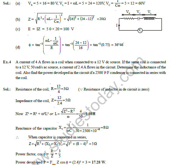
Ex.3 A resistance R, an inductance L and capacitor C are connected in series with an AC supply where R = 16Ω, inductive reactance XL = 24Ω and capacitive reactance XC = 12Ω. If the current in the circuit is 5 ampere find
(a) P.D. across R, L and C
(b) impedance of circuit,
(c) voltage of AC supply and
(d) phase angle.
[Figure: Series circuit with R, L and C in a row. Voltage across R is VR, across C is VC and across L is VL, with the AC supply VS across the whole series combination and current I flowing through all three.]
Answer:
(a) P.D. across R, L and C
1. VR = I × R = 5 × 16 = 80 V.
2. VL = I × XL = 5 × 24 = 120 V.
3. VC = I × XC = 5 × 12 = 60 V.
(b) Impedance of circuit
1. Z = √(R² + (XL - XC)²) = √(16² + (24 - 12)²) = √(256 + 144) = √400 = 20 Ω.
(c) Voltage of AC supply
1. E = I × Z = 5 × 20 = 100 V.
(d) Phase angle
1. φ = tan⁻¹((XL - XC)/R) = tan⁻¹(12/16) = tan⁻¹(0.75) = 36.87°, that is 36°52′.
Teacher's Note:
a) The printed phase angle 36°46′ is wrong; tan⁻¹(0.75) is 36°52′.
b) Check that the three voltages VR, VL and VC do not add arithmetically; the supply voltage is found from Z.
c) The phase angle is positive here, so the current lags the supply voltage because XL is greater than XC.
Ex.4 A current of 4 A flows in a coil when connected to a 12 V dc source. If the same coil is connected to a 12 V, 50 rad/s ac source, a current of 2.4 A flows in the circuit. Determine the inductance of the coil. Also find the power developed in the circuit if a 2500 μF condenser is connected in series with the coil.
Answer:
1. Resistance of the coil: R = V/I = 12/4 = 3 Ω. (The inductor has no effect on a dc source, so only R is measured.)
2. Impedance of the coil with ac: Z = 12/2.4 = 5 Ω.
3. Z² = R² + ω²L², so L = √(Z² - R²)/ω = √(25 - 9)/50 = 4/50 = 0.08 H.
4. Reactance of the inductor: XL = ωL = 50 × 0.08 = 4 Ω.
5. Reactance of the capacitor: XC = 1/(ωC) = 1/(50 × 2500 × 10⁻⁶) = 1/0.125 = 8 Ω.
6. Impedance with the capacitor in series: Z = √(R² + (XL - XC)²) = √(3² + (4 - 8)²) = √25 = 5 Ω.
7. Current I = V/Z = 12/5 = 2.4 A, and power factor cos φ = R/Z = 3/5 = 0.6.
8. Power developed P = V × I × cos φ = 12 × 2.4 × 0.6 = 17.28 W.
Teacher's Note:
a) A dc source gives the resistance only, because the inductor offers no reactance to direct current.
b) The power is taken from the resistance only, so P = I²R = 2.4² × 3 = 17.28 W gives the same answer.
c) Adding the capacitor makes the impedance equal to 5 Ω here, which is why the current stays 2.4 A.
Ex.5 A 100 V a.c source of frequency 500 Hz is connected to a series LCR circuit with L = 8.1 mH, C = 12.5 mF and R = 10 Ω. Find the potential difference across the resistance.
Answer:
1. Inductive reactance XL = 2π × 500 × 8.1 × 10⁻³ = 25.45 Ω.
2. Capacitive reactance XC = 1/(2π × 500 × 12.5 × 10⁻⁶) = 25.46 Ω.
3. Since XL = XC, the circuit is at resonance.
4. At resonance, VL = VC, so the impedance is Z = R and V = √(VR² + (VL - VC)²) = VR.
5. Hence, VR = 100 V.
Teacher's Note:
a) The capacitance is 12.5 μF, not 12.5 mF; the printed reactance 25.478 Ω is only correct for 12.5 μF.
b) At resonance, the whole supply voltage appears across the resistance.
c) Resonance frequency 1/(2π√(LC)) is 500 Hz here, which confirms the condition.
Ex.6 Two inductances of 5.0 H and 10.0 H are connceted in parallel circuit. Find the equivalent inductance and r.m.s. voltage in each inductor and in mains circuit when connected to a source of 10 V AC.
[Figure: Two inductors of 5.0 H and 10.0 H connected in parallel across a 10 V AC source. Current I1 flows through the 5.0 H inductor, current I2 through the 10.0 H inductor, and the total current I is drawn from the mains.]
Answer:
1. For inductors in parallel: 1/L = 1/L1 + 1/L2 = 1/5 + 1/10 = 3/10.
2. Equivalent inductance L = 10/3 H = 3.33 H.
3. Assume the supply frequency is 50 Hz, as the solution uses, so ω = 2π × 50 rad/s.
4. The inductors are in parallel, so the r.m.s. voltage across each inductor is 10 V, the same as the mains voltage.
5. Irms in L1 = V/(ωL1) = 10/(2π × 50 × 5) = 1/(50π) A.
6. Irms in L2 = V/(ωL2) = 10/(2π × 50 × 10) = 1/(100π) A.
7. Irms in the mains circuit = 1/(50π) + 1/(100π) = 3/(100π) A = 0.0095 A.
Teacher's Note:
a) The question does not give the frequency; the solution uses 50 Hz, which should be stated in the answer.
b) The current in the mains is the sum of the branch currents, not the sum of the inductances.
c) Check the mains current with the equivalent inductance: V/(ωL) = 10/(2π × 50 × 10/3) = 3/(100π) A, which agrees.
Ex.7 A 750 hertz, 20 V source is connected to a resistance of 100 ohm, an inductance of 0.1803 henry and a capacitance of 10 microfarad all in series. Calculate the time in which the resistance (thermal capacity = 2 joule / °C) will get heated by 10 °C ?
Answer:
1. Inductive reactance XL = ωL = 2 × 3.14 × 750 × 0.1803 = 849.2 Ω.
2. Capacitive reactance XC = 1/(ωC) = 1/(2 × 3.14 × 750 × 10 × 10⁻⁶) = 21.23 Ω.
3. Impedance Z = √(R² + (XL - XC)²) = √(100² + (849.2 - 21.23)²) = 834 Ω.
4. Power dissipated P = Vrms × Irms × cos φ = Vrms² R/Z² = (20/834)² × 100 = 0.0574 W.
5. Heat required to raise the temperature by 10 °C: H = 2.0 × 10 = 20 J.
6. Using H = P × t, t = H/P = 20/0.0574 = 348 s.
Teacher's Note:
a) Power is dissipated only in the resistance, so use Vrms²R/Z².
b) The printed value 0.0575 W is a rounded figure; 0.0574 W gives t of about 348 s.
c) Heat is in joules, and the thermal capacity of 2 J/°C gives 20 J for a rise of 10 °C.
Ex.8 A series LCR circuit containing a resistance of 120 Ω has angular resonance frequency 4 × 10⁵ rad s⁻¹. At resonance, the voltage across resistance and inductance are 60 V and 40 V respectively. Find the values of L and C. At what frequency the current in the circuit lags the voltage by 45°?
[Figure: Phasor diagram with VR along the current direction, VL upward at 90° and VC downward. The resultant of (VL - VC) and VR gives the source voltage, which leads the current by 45°.]
Answer:
Values of L and C
1. For the resistance, VR = Irms R, so Irms = 60/120 = 0.5 A.
2. For the inductor, VL = Irms ω0L, so 40 = 0.5 × 4 × 10⁵ × L.
3. L = 40/(2 × 10⁵) = 2 × 10⁻⁴ H.
4. At resonance, ω0L = 1/(ω0C), so C = 1/(ω0²L) = 1/((4 × 10⁵)² × 2 × 10⁻⁴) = 1/(3.2 × 10⁷) F = 1/32 μF = 0.03125 μF.
Frequency at which the current lags the voltage by 45°
1. The current lags the voltage by 45°, so tan 45° = (ωL - 1/(ωC))/R = 1, which gives ωL - 1/(ωC) = R.
2. Substitute 1/(ωC) = ω0²L/ω, so ωL - ω0²L/ω = R.
3. Multiply by ω: ω²L - ω0²L = Rω, which gives 2 × 10⁻⁴ ω² - 120 ω - 2 × 10⁻⁴ × (4 × 10⁵)² = 0.
4. Divide by 2 × 10⁻⁴: ω² - 6 × 10⁵ ω - (4 × 10⁵)² = 0.
5. Solve: ω = (6 × 10⁵ ± √(36 × 10¹⁰ + 64 × 10¹⁰))/2 = (6 × 10⁵ ± 10 × 10⁵)/2, so ω = 8 × 10⁵ or -2 × 10⁵.
6. Reject the negative root. Hence ω = 8 × 10⁵ rad/s, which is a frequency of about 1.27 × 10⁵ Hz.
Teacher's Note:
a) The printed step "ω²L - ω₀²L = 2ω" should read "Rω = 120ω", because the resistance is 120 Ω.
b) The answer is an angular frequency, so the unit is rad/s, not Hz.
c) Use the resonance condition to eliminate C before forming the quadratic equation.
Ex.9 A LCR circuit has L = 10 mH, R = 3 ohm and C = 1μF connected in series to a source of 15 cos (ωt) volt. Calculate the current amplitude and the average power dissipated per cycle at a frequency that is 10% lower than the resonant frequency.
Answer:
1. Resonant frequency ωR = 1/√(LC) = 1/√(10 × 10⁻³ × 1 × 10⁻⁶) = 1/√(10⁻⁸) = 10⁴ rad/s.
2. Frequency 10% lower: ω = 10⁴ - 10⁴ × 10/100 = 9 × 10³ rad/s.
3. XL = ωL = 9 × 10³ × 10 × 10⁻³ = 90 Ω.
4. XC = 1/(ωC) = 1/(9 × 10³ × 1 × 10⁻⁶) = 111.11 Ω.
5. Z = √(R² + (XL - XC)²) = √(3² + (90 - 111.11)²) = √454.5 = 21.32 Ω.
6. Current amplitude I0 = E0/Z = 15/21.32 = 0.704 A.
7. Power factor cos φ = R/Z = 3/21.32 = 0.141.
8. Average power P = ½ E0 I0 cos φ = ½ × 15 × 0.704 × 0.141 = 0.742 W.
Teacher's Note:
a) The printed average power 0.744 W comes from rounding the intermediate values; the value from unrounded numbers is 0.742 W.
b) Use the peak voltage E0 = 15 V with the factor ½ for average power.
c) At a frequency below resonance the circuit is capacitive, so XC is greater than XL.
Free study material for Physics
Free CBSE Study Guides: Class 12 Physics Chapter 07 Alternating Current
Essential Notes for Class 12 Physics
Review targeted study resources for Chapter 07 Alternating Current tailored for Class 12 learners. Utilizing these structured notes and quick-revision tools ensures complete alignment with current CBSE evaluation standards.
Verified Solutions for Class 12 Physics
Designed around the official curriculum, these study guides guarantee standard compliance. Reviewing step-by-step solutions clarifies complex sub-topics within Chapter 07 Alternating Current and demystifies standard marking schemes for Physics evaluations.
Enhance Accuracy with Online Tests
For peak performance in upcoming evaluations, integrate official Physics sample papers directly into your study schedule. Follow up your revision by attempting online MCQ tests for Chapter 07 Alternating Current to refine calculation speed and precision.
FAQs
Our advanced study package for Chapter 07 Alternating Current includes detailed concepts, diagrams, Mind Maps, and explanation of complex topics to ensure Class 12 students learn as per syllabus for 2026 exams.
The Mind Maps provided for Chapter 07 Alternating Current act as visual anchors which will help faster recall during high-pressure exams.
Yes, teachers use our Class 12 Physics resources for lesson planning as they are in simple language and have lot of solved examples.
Yes, You can download the complete, mobile-friendly PDF of the Physics Chapter 07 Alternating Current advanced resources for free.
Yes, our subject matter experts have updated the Chapter 07 Alternating Current material to align with the rationalized NCERT textbooks and have removed deleted topics and added new competency-based questions.